Week 11 - Project - A pillar Design with Master Section
AIM:
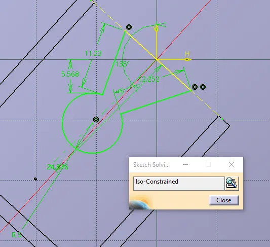
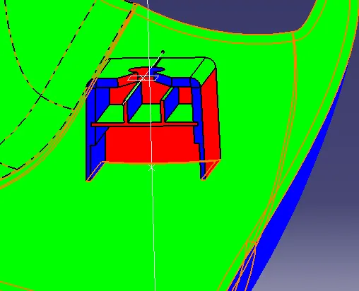
To create the A Pillar Design with the master section given as the intersection sketch with the Class A surface and create the tooling axis and perform the Draft analysis for the final solid part.
Class A
Class-A surface is input surface used as a reference surface for surface B creation. It provides the aesthetic team's look for the component, which the part design engineer uses to develop the component with all of the engineering requirements.
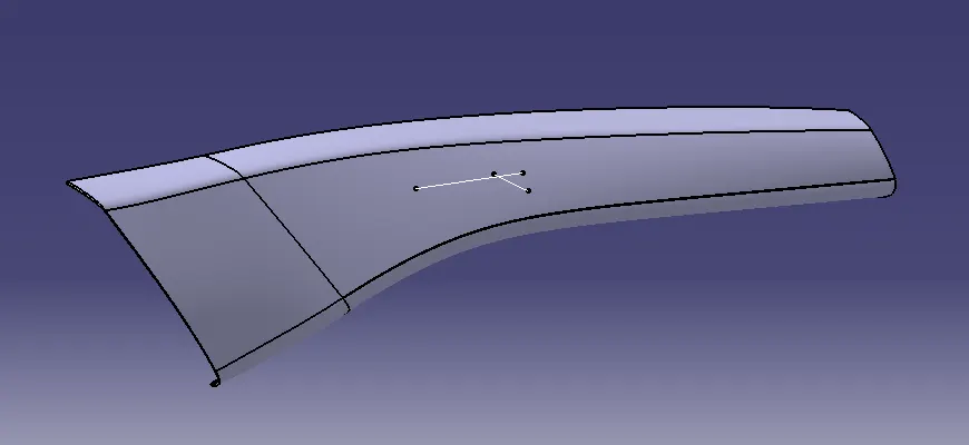
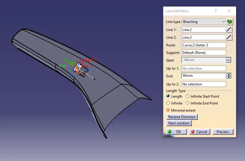
Tooling axis-Bisecting line Method
The bisecting line method is essentially used to identify the correct tooling axis.
To create bisecting line two line and reference point is needed.
So, by taking the intersection at XZ-plane two lines were created and point was created.
By that tooling axis was created.
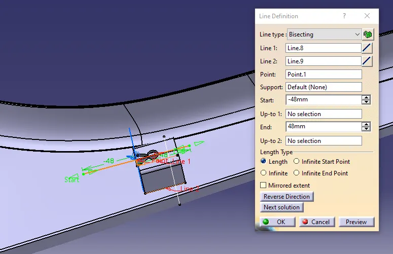
Side Core Axis
This axis is used to do drat analysis of dog house.
Using the bisecting line method or create using the given master section create the side clearance axis for the dog house.
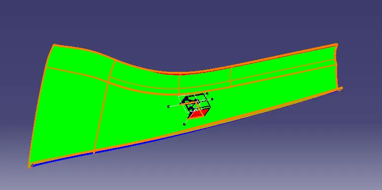
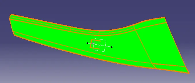
Draft Analysis of class A
After locating the compass and aligning it with the tooling axis, click on the lock symbol after aligning, and then click again on the surface after opening the draft analysis tool box.
Creating Class B Surface:
First, offset the surface to 2.5mm was created and by using different methods closed surface was created.
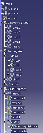
List of different command is given below:
Creating Class C Surface:
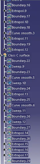
Class c surface is created by using sweep, extrapolation, trimming, joining etc.
Final output :
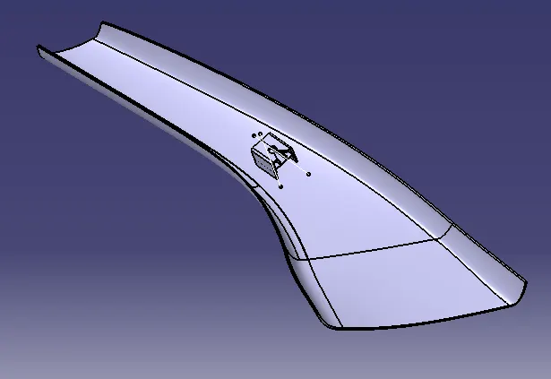
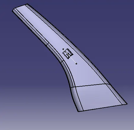
Trimming all surface final output was created.
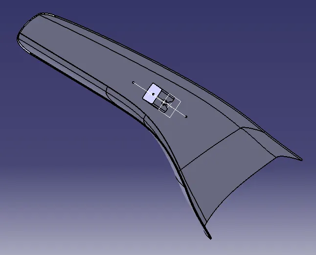
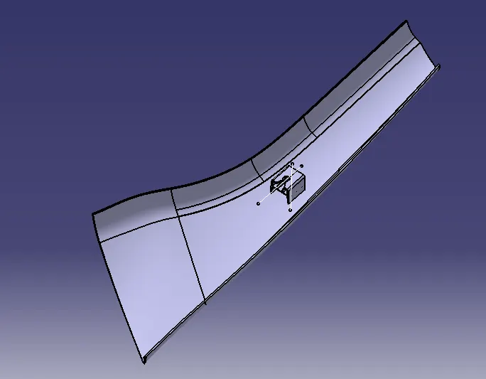
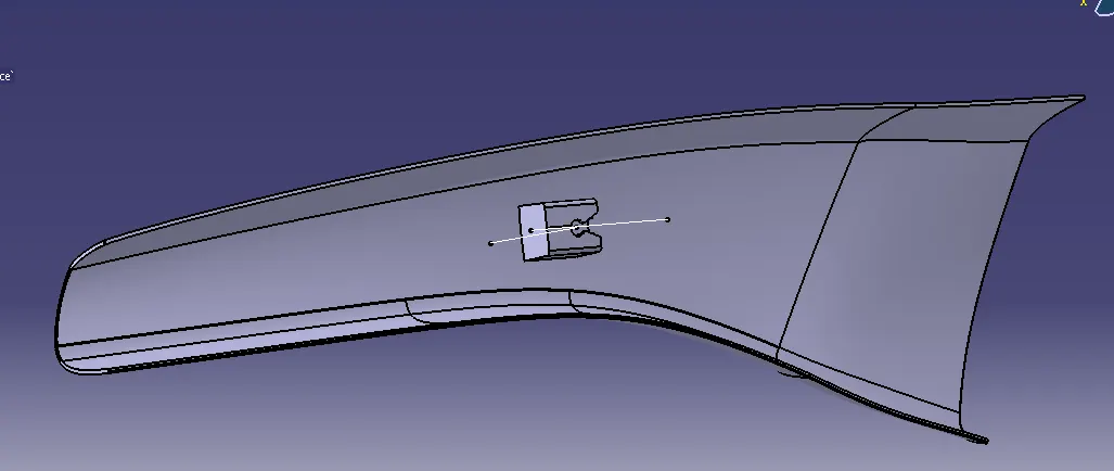
DOG HOUSE
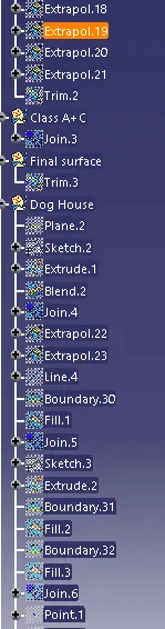
Dog house is used as a fitting element for the trim. Now using given master section dog house created and using it’s curves side core axis is created.
DOG HOUSE Creation
Rules of dog house are given below:
C thickness should be 40% of the main wall thickness T
Minimum width of the dog house is 12 mm.
Height of B should be 3-6 mm
Final Draft analysis
Drafting analysis is done to check whether a component can be manufactured by injection molding or not.
For component draft angle value is 3 degrees.
For side core axis draft angle is kept 1.5 degrees.
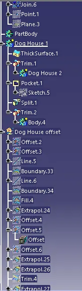
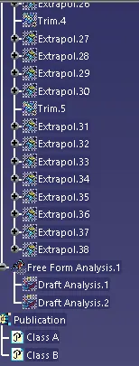
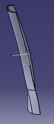
Now images of views and tree structures are given below: