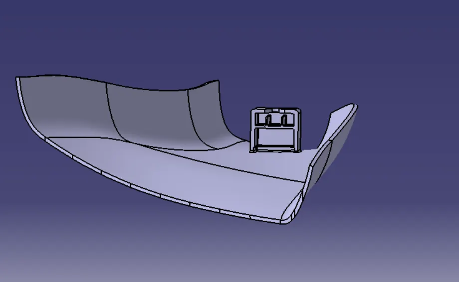
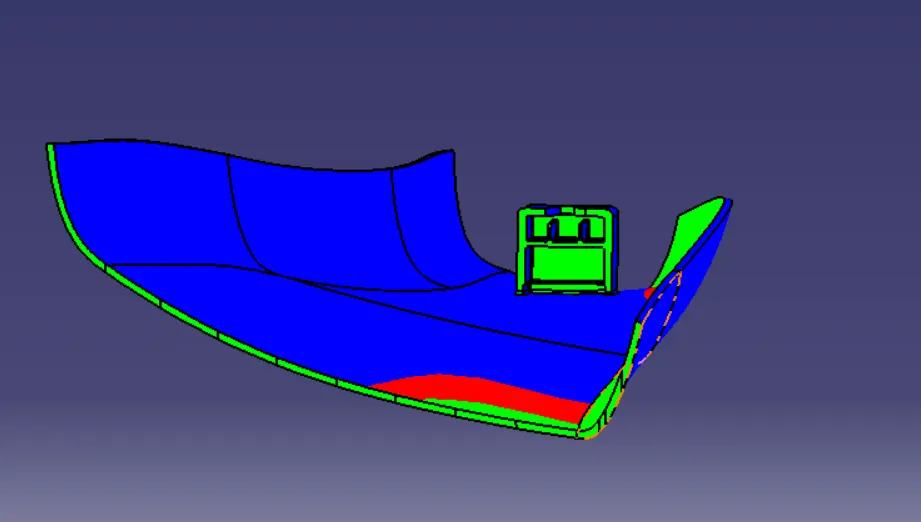
Week 11 - Project - A pillar Design with Master Section
OBJECTIVE: To create the A-Pillar's Plastic component from the given Class A Surface using the Master Section that is provided while following all the design rules.
INTRODUCTION:
Types of Pillars and their Importance in the Automotive Industry:-
These pillars standing at the vertical or near-vertical (slightly inclined) position are structural supports for the car's roof and window areas.
They are pretty important as they provide a strong foundation to install the glass (windscreens, rear, and side windows) of your car. Also, these are strong enough to hold the entire roof (even with roof racking to carry additional weights).
There are several pillars your car can have, and each has got a name. Pillars are named “A”, “B”, “C”, or “D” (in larger vehicles), if you move from the front to the rear end of your vehicle.
The number of pillars will vary from car to car.
For example, most sedans and hatchbacks will have three (A, B & C) pillars whereas larger cars like SUVs will have all four (A, B, C & D) pillars.
Hardtop structures (often referred to as pillarless hardtops) will have only two (A & C) pillars.
ROLE OF THE A-PILLAR:
A-Pillar is located on either side of your car’s front window (or windshield).
They also hold the hinges of your front doors. A-pillars are normally made of steel alloys.
Besides being a supporting member, A-pillars are very crucial as far as safety is concerned. A-pillars usually carry a significant amount of load during a frontal collision or a rollover crash. So the larger the width or cross-section, the greater would be the strength but A-pillars always block the driver’s vision (create blind spots) to some extent that can be realized while driving. So, having that said, using thicker A-pillars can make the situation even worst. It might further lower the driver’s vision and raise a question about the vehicle’s and passenger’s safety.
Hence, the design of A-pillars must be optimized giving equal importance to both strength and the driver’s vision.
Firstly, we have to create the required Tooling-Axis for the given Class A Surface while meeting the requirements of the necessary Draft Angle & then perform the Draft-Analysis Operation on the Class A Surface itself.
After that, we have to create the required Class B & Class C Surfaces using which we have to make the Final Plastic Component and perform Draft Analysis on it.
MAIN REPORT:
Types of Surfaces and their importance for an Automotive Plastic Designer:
- Class A Surface: Class A is an aesthetic surface with the highest quality finish. Most Class A Surfaces for an Automotive Component are made using 'Autodesk-Alias' based on the final Concept-Sketch. All Class A surfaces should have 'Curvature-Continuity', meaning the continuity between the surfaces should share the same boundary. It is taken as a reference by the Automotive Plastic Designer to create 'Class B' and 'Class C' Surfaces.
- Class B Surface: The Class B Surface resides below the Class A Surface at a certain thickness. It is created using Engineering Principles that consist of all the necessary features such as Ribs, Bosses, Snaps, etc. This surface isn't visible to the observer from the outside.
- Class C Surface: The Class C Surface is the surface created between the Class A and Class B surfaces to join them with each other.
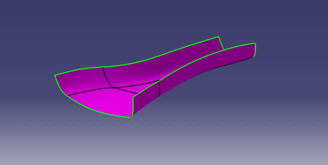
Now, we will begin by checking the State of Connectivity for the Class A Surface and ensure that there are no gaps between the surfaces as all the surfaces should be joined well together with each other and shouldn't consist of any discontinuities between them.
Our Class A Surface:
PROCEDURE TO CREATE THE MAIN TOOLING AXIS:
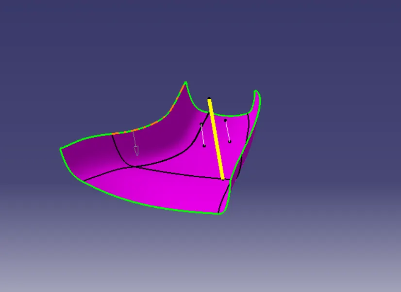
Since we have a Master Section provided to us using which we have to create the desired A-Pillar Plastic Component, We'll use that Master Section by extracting the lines as shown below and create a Bisecting Line with respect to those extracted lines to create our Main Tooling Axis.
DRAFT ANALYSIS ON THE CLASS A SURFACE:
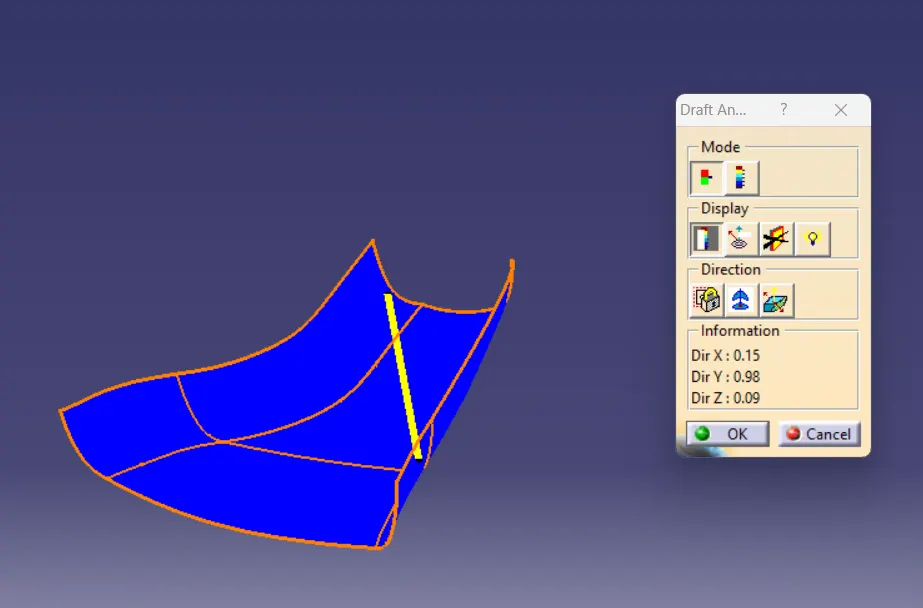
Next, We will perform a Draft Analysis on the Class A Surface itself:
Before starting with a Draft Analysis Operation, we will go to the 'Customize View Parameters' option under the 'View Toolbar'. Then we will enter the 'Customize View Mode' where we will go under the 'Mesh' option and select 'Material' and press 'OK'.
To start the Draft Analysis in the 'Generative Surface Design Workbench', we will go to 'Insert' and then look for the option called 'Analysis'. Once found, we will go under that and click on 'Feature Draft Analysis. This will open the 'Draft Analysis' Dialogue box. There, we will ensure that under 'Mode' we have selected 'Quick Analysis', under 'Display' we will select 'Show or Hide the Color Scale' and then select '3 Degrees' as the permissible draft angle. Then, under 'Direction' we will choose the icon with the symbol of the compass on it which stands for 'Use the Compass to define the new current draft direction'.
PROCEDURE TO CREATE THE CLASS B SURFACE:
We'll offset the Class A Surface by 2.5mm as shown below:
It is not offsetting properly due to the complexity of the curvature of the Class A Surface and hence we have to recreate that missing patch using tools such as Sweep Command as shown below.
We'll create two boundaries as shown below so that we can use the sweep command on it:
We'll create it using Reference Surface in the Sweep Command and Then, we'll join the newly created surface with the main offset obtained from the Class A Surface.
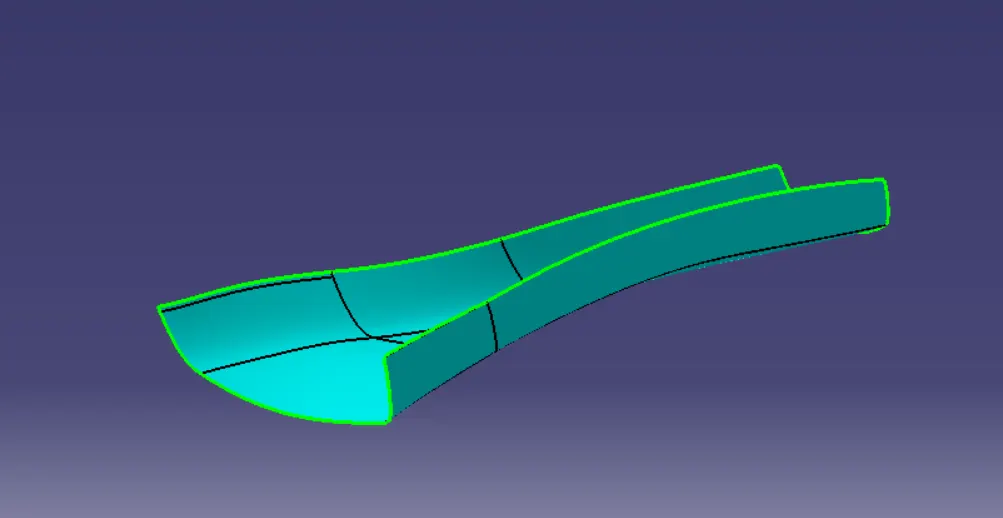
Hence, our Class B Surface is created.
PROCEDURE TO CREATE THE CLASS C SURFACE:
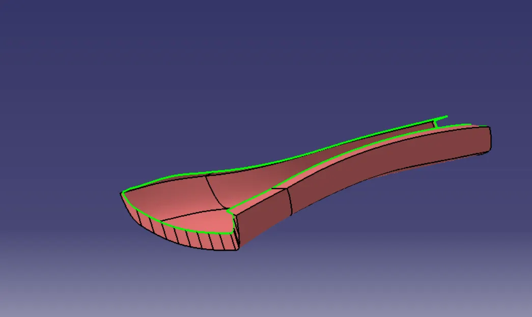
To create the Class C surface firstly we have to unhide the Class A Surface and extract it's boundaries and We're going to smoothen these extracted boundaries using 'Curve Smooth'. Then we're going to use the 'Sweep' command with 'Reference Surface' & 'With Draft Direction' to create the Class C Surface as shown below:
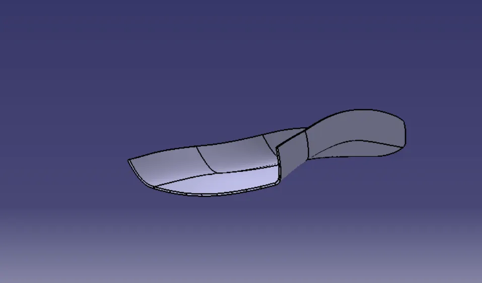
Then, we going to trim it with the Class B surface. To ensure that it will be feasible to trim the Class B surface with the joint surface of Class A & C, we're going to extrapolate the Class B surface by a small amount to obtain the closed body as shown below:
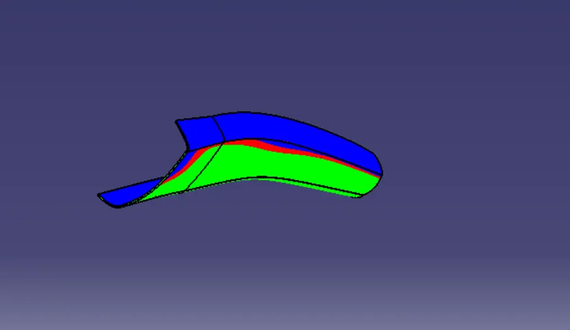
DRAFT ANALYSIS FOR THE CLOSED BODY USING THE MAIN TOOLING AXIS:
PROCEDURE TO CREATE THE ENGINEERING FEATURE- DOGHOUSE USING THE MASTER SECTION:-
Using the Master Section we can create a sketch that can be extruded to create the doghouse's walls. Using the Multi-Sections Surface command we're going to create the rear wall of the doghouse Then, we'll join them all together and move on to the Part Workbench to thicken it by 2.5mm.
After that, we're going to provide all the required drafts using the 'Draft Angle' command in Part Workbench.
Draft Angle is provided at both the outer and inner sections of the doghouse with respect to the Main Tooling axis and Side-Core axis respectively.
Then, using the Master Section, we're going to create the inner walls of the doghouse and We've to provide the draft to these walls with respect to the Side-Core axis also We'll also provide the Edge-Fillet as found in the Master Section with a radius of 1.5mm.
PROCEDURE TO PERFORM THE CORING OPERATION:
Firstly, we'll create a Multi-Section Surface that will be the base section of the Doghouse Then, we'll extrapolate it using Point Continuity and then offset it by 4mm. After that, we'll extract the inside walls of the doghouse using the extract command and trim it with the offseted surface.
Now, we'll offset this surface by 0.708mm because we need a 1mm width for the walls of the doghouse to avoid sink mark formations and the current width is 1,708mm.
We'll offset it and then extrapolate it so that we can carry out the split operation easily.
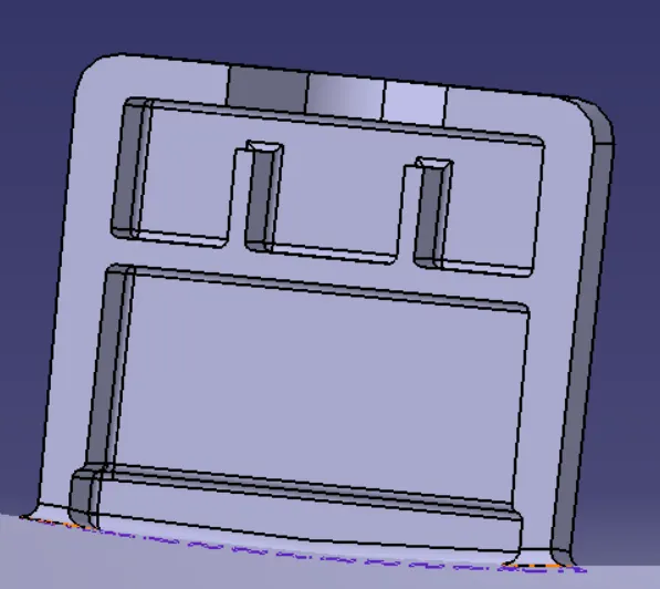
Finally, using the Boolean Operation, we're going to add the Doghouse to the Closed Body of the A-Pillar as shown below: