Fender Design - Wheel Arch Challenge
AIM:
To create a report on fender regulation and to calculation the wheel arc area and prove whether the car will pass the standards or not by using the European standards.
Fender:
A fender is the part of a car, truck, motorcycle, or other vehicles that frames or covers a wheel well. Its main purpose is to prevent debris, rocks, mud, liquids, sand, and other road debris from getting thrown in the air while the tires rotate.
The “fender” typically refers to the front panel that covers the front wheels, and the “quarter panel” typically refers to the rear panel that covers the wheel that also includes the roof pillar. The “bumper” is the front and rear ends of a motor vehicle to absorb impact in a minor collision.
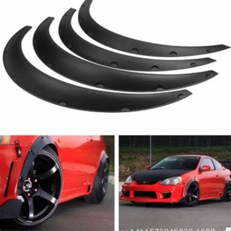
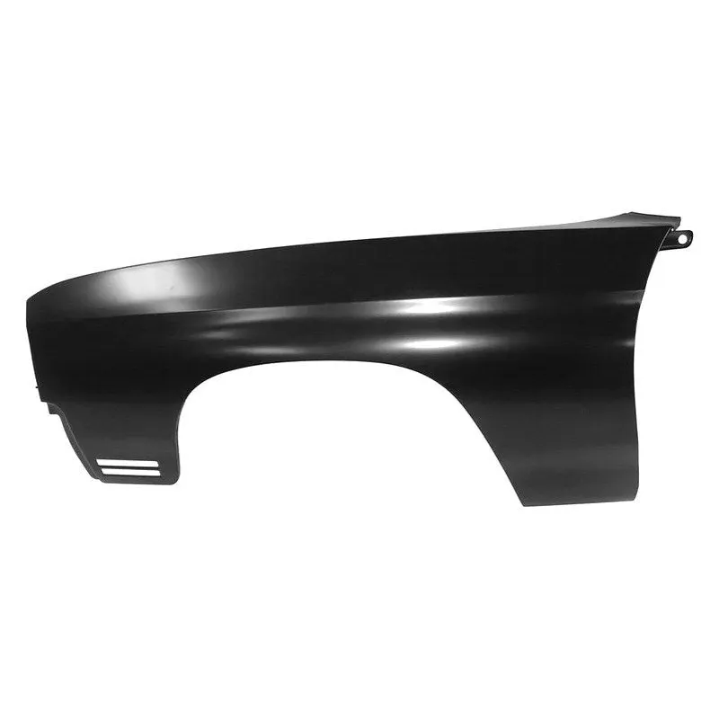
Types of fender:
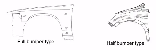
The type of fender is based upon the area covered i.e. full fender type and half fender type.
Full bumper type : The full fender type is a more conventional fender style that uses more material. This type is utilised in older automotive designs where it adds to overall weight and lowers performance. Because to increased surf, maintenance costs have also increased.
Half bumper type : Half fenders are a modern design that uses less material and boosts productivity by allowing for a smaller blank size. In comparison to full bumper types, maintenance is also comparatively low.
There are many factors that need to be considered during designing the fenders of the vehicle. One of them is the wheel arch area.
In a fender, the wheel arch is the semicircular part that is positioned above the wheel of the vehicle. While designing the fender care must be taken that the wheel arch of the fender meets the required standards.
Different standards of the wheel arch area requirements:
- The wheel should be placed inside the fender or in other words, there should be a minimum distance between the outer surface of the fender and outer surface of the wheel.
- This helps to reduce the chance of chipping of the wheel with outer particles.
- It helps in increasing pedestrian safety.
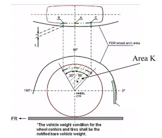
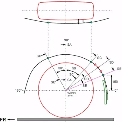
The distance ‘L’ as mentioned in the above figure should be a minimum value, which varies as per standards followed by different countries
Some of the different standards followed are:
- Japanese standards.
- European standards.
- US standards.
1.Japanese standards:
- Measure clearance L of the tire, hub, cap, and fender in three different positions within area K and produce a clearance check chart to validate.
- Clearance must be greater than 5 mm in all the three positions (i.e., at A, B, C from fender curvature)
- Wheel guard requirement: The value of 'a' shall be more than 5 mm at line 30* forward and 50* rearward from the central vertical axis of the wheel.
2.European standards:
- According to european requirements the distance is measured at 5 different points.
- Measure CL L at sections SA-SA SB-SB SC-SC SD-SD SE-SE and produce CL check chart to validate.
- At all five sections the CL L value should be greater than 10 mm to satisfy the European regulations.
- ✓ Wheel guard reqmt: The value of 'a' shall be more than 5 mm at a line 30* forward and 50* rearward from the central vertical axis of axis of wheel.
3.US standards:
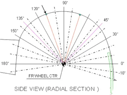
- The clearance ‘L’ at all positions (every 10o) from -20 deg to 180 deg should be greater than 5 mm to satisfy US regulations.
Wheel Arc Verification Using European Standards:
The clearance between the wheel and the fender during vehicle bump circumstances is a crucial factor that is taken into account when building a wheel arch or wheel. The minimum required wheel arc distance from the wheel for safety has been proposed as requirements by the vehicle and road safety community.
Rules -
- The sections SA, SB, SC, SD, and SE are used to measure CL L.
- The value of CL L should be more than 10mm at all parts.
- The need for a wheel guard: The value of a must be more than 5mm at 30 degrees forward and 50 degrees back from the wheel's centre.
The below fig shown the sketch is drawn on the wheel face as per the European Standards,
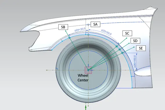
Fig: (3) Wheel Arch
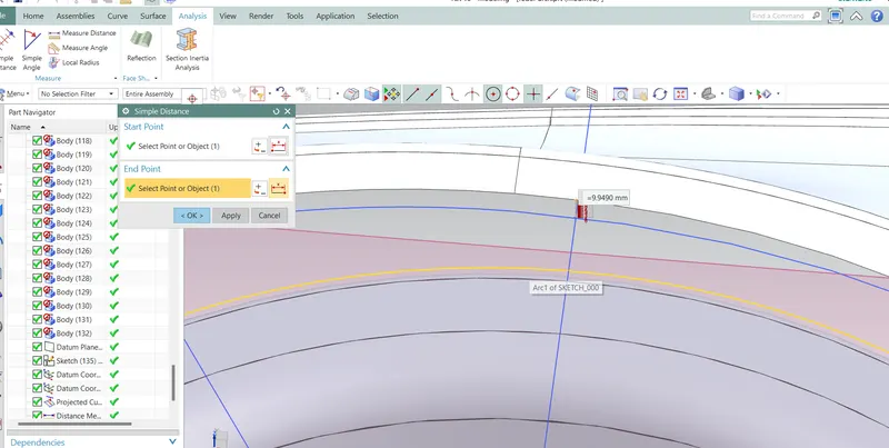
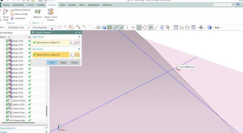
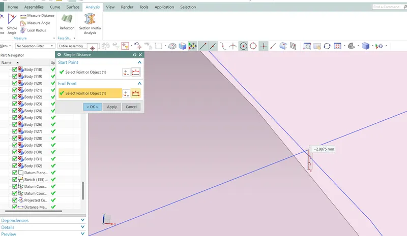
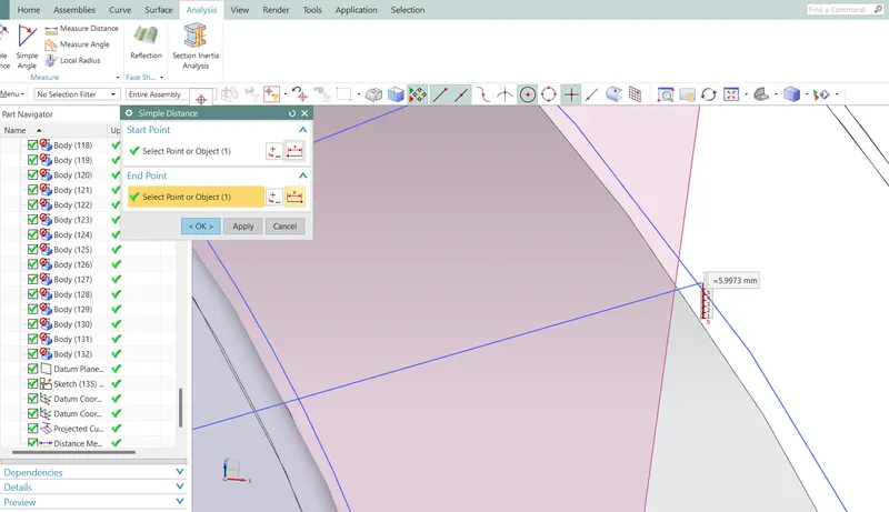
In the above fig- we have opened the given file on Siemens NX CAD 10. Firstly, create the point on the centre of wheel and then create the centre reference line. project the on the wheel arch at section SA, SB, SC, SD and SE to measure the distance / clearance 'L', 'a' and the wheel arch area.
Calculation of the clearance value "L" as following:
1] The Measuring 'L' for the given wheel and fender at SB- The value of 'L' at SB= 10.0000 mm.
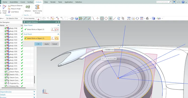
2] The Measuring 'L' for the given wheel and fender at SA- The value of 'L' at SA= 9.9490 mm.
3] The Measuring 'L' for the given wheel and fender at SC- The value of 'L' at SC= 0.113949 mm
4] The Measuring 'L' for the given wheel and fender at SD- The value of 'L' at SD= 2.8875 mm
5] The Measuring 'L' for the given wheel and fender at SE- The value of 'L' at SE= 5.9973 mm.
|
Sl no. |
Section |
Distance/clearance “l” (mm) |
Result |
|
1. |
SB |
10.000 = 10 |
Positive |
|
2. |
SA |
9.9490 < 10 |
Negative |
|
3. |
SC |
-0.113949 |
Negative |
|
4. |
SD |
-2.8875<10 |
Negative |
|
5. |
SE |
-5.9973<10 |
Negative |
Conclusion:
- Hence from the above observations, since the positions SA, SC, SD, and SE have a clearance of less than 10mm which is the minimum requirement for the European regulations, it is clear that the front fender's wheel arch area does not pass the European Regulations.
- The styling team is required to modify the styling surface of the fender such that the clearance \"L\" at sections SA, SC, SD and SE is equal to or greater than 10 mm by increasing the curvature at those sections towards outside.