Week 11 - Project - A pillar Design with Master Section
A-pillar Design with mastersection
Creating the tooling axis, b class, C class and trimmed with A class surface is the first step for design other engineering in the A-pillar. Analyzing the mastersection and appying the design features based on the particular mastersection help us to reduce more time spending with unneccesary details. Draft analyzing is one of the most important part in the challenge.
Requirement in output
- Picture of the sketches with Sketch solving status’s geometry tab
- Picture of the Detailed tree structure.
- Picture of the 3D CAD
- Create closed body
- Create a tooling axis and follow design rules.
- Follow the Master section to create a flange
- Follow the master section for thickness and to create the Closed volume.
- Follow the master section to create Attachment features
- The thickness of the Plastic to be 2.5 mm
Tooling axis
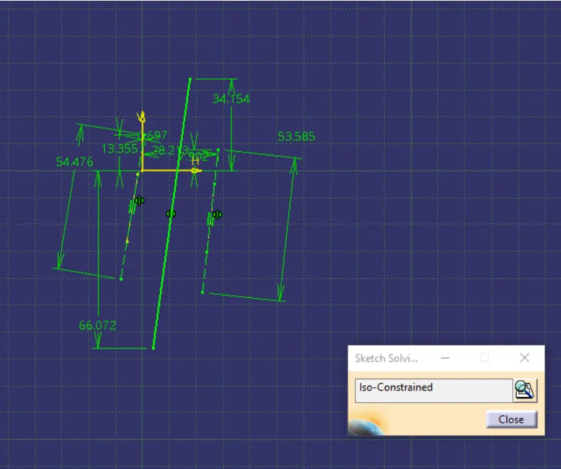
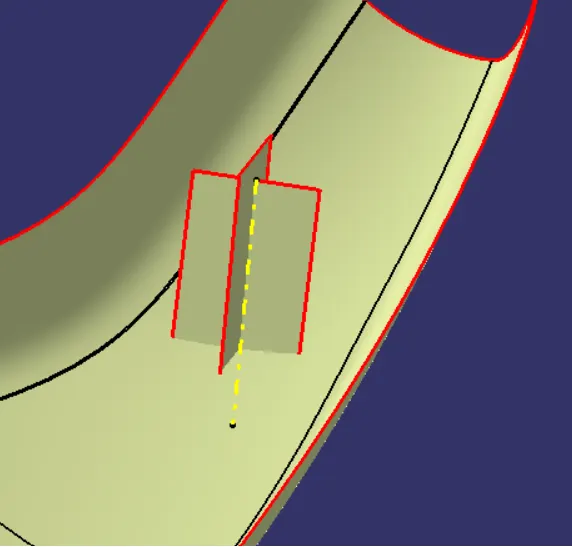
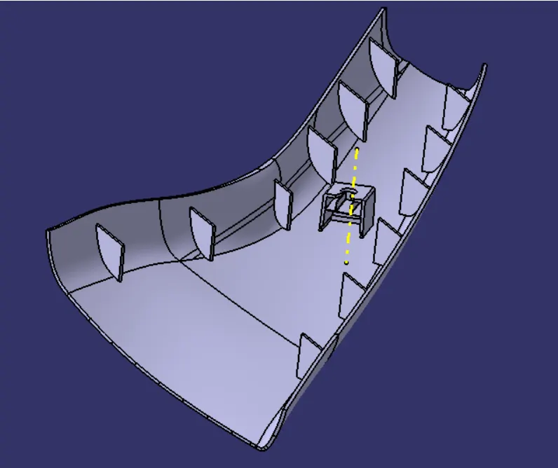
Im initiated from tooling axis which took reference from the dog house faces mastersection. I'm projected both lines from mastersection and trimmed to required length. After that I'm extruded the lines to intersect with other extruded line. This helped me to find intersection curve as tooling axis.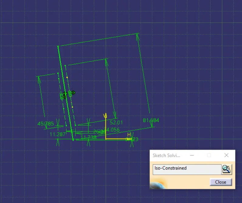
Class -A surface
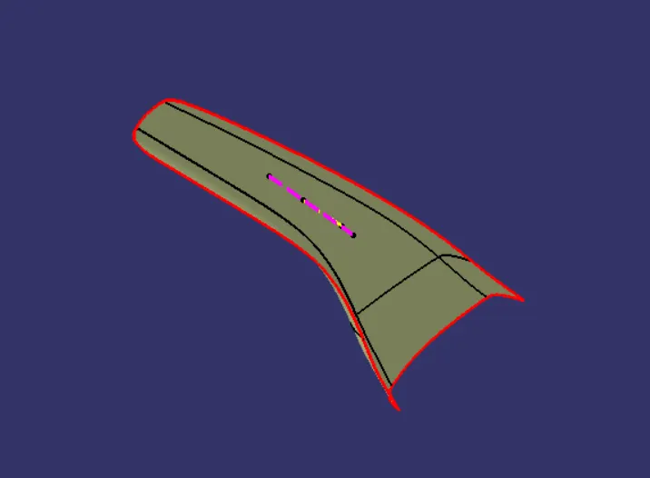
Once got a input I checked the boundaries of the A class surface. Its quit smooth surface and not patches there so without makeup I used the class A for next steps.
Class -B surface
Class A surafce was just offsetted to the mentioned thickness of 2.5mm in upward direction. But this time the fillets are not dissappeared luckily.
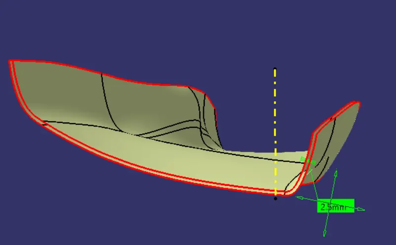
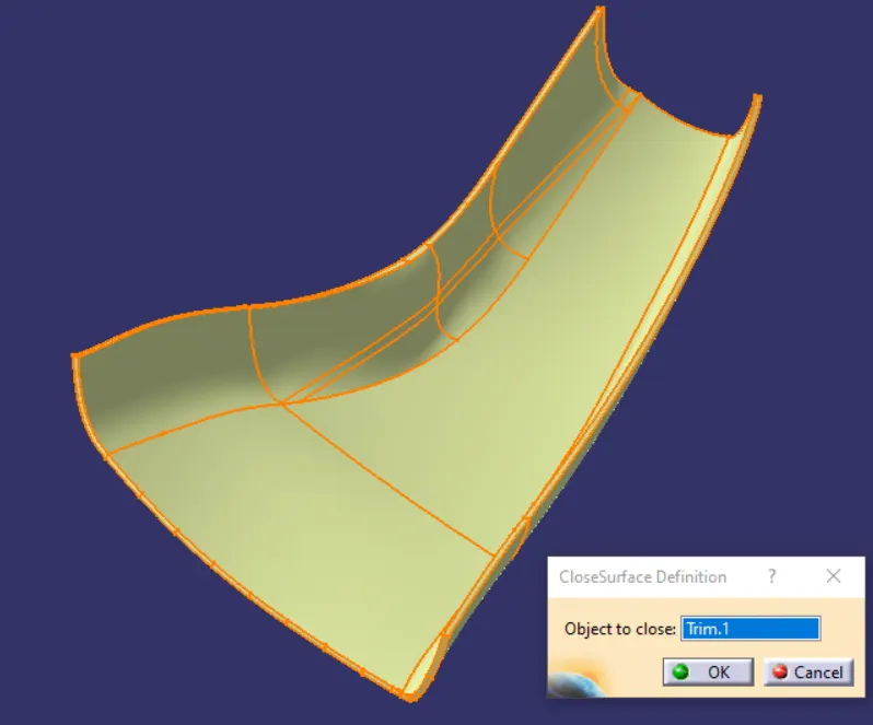
Close surface
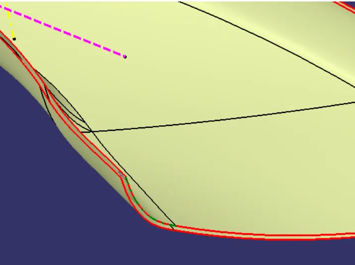
The two parallel surfaces are joined by the class C surface. C class surface was just created by the swept tool. After succeeded in the mission of close the surfaces without any boundary errors I jump into convert this surfaces to body. For that I'm used close surface tool from part workbench.
Attachment feature
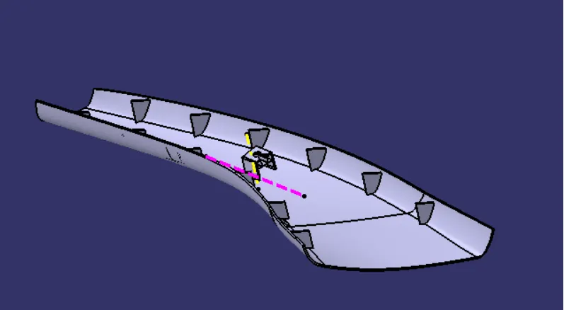
The attachment features for the A-pillar are doghouse and ribs.
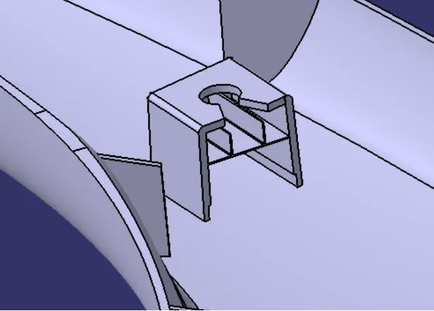
Doghouse
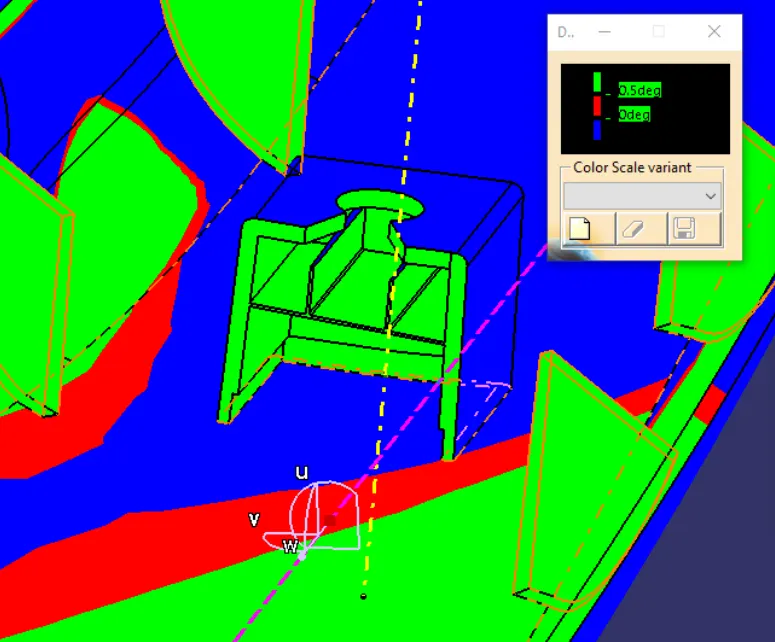
Dog house designed by the mastersection which was given in the input. The draft were applied to achieve the 0.7 degree of draft.
Ribs
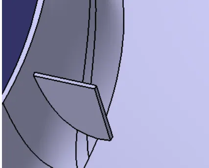
I'm initiated with making points on the surface using repetition point and make it as line. After I extruded the line to 25mm length and 2mm of thickness using thicken tool.
Ends with the draft of 0.7 degree.
Draft analysis using tooling axis
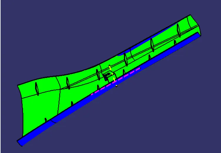
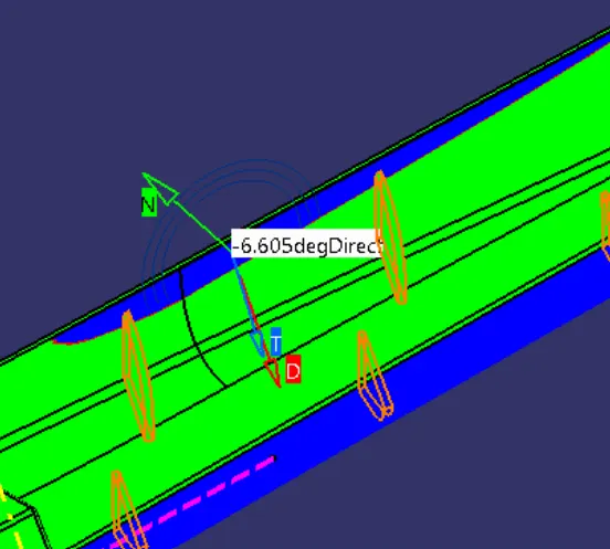
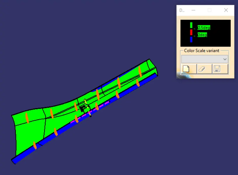
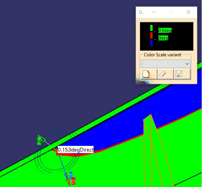
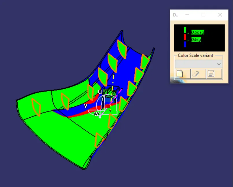
Using the tooling axis and the minimum draft angle of 0.5 degree the draft analysis was initiated. The result what I got was shown in below. Some surfaces are not green that shows some attention must needed. The blue shows less than 0 degree and red shows greater than 0 but not 0.5 degree or above.