Week 9 - Challenge 2 - Switch Bezel Design
Aim
The aim of this project is to develop the product design of the switch bezel with the help of the class A surface following the OEM standards.
Introduction
Class A
Class A surface is the term mainly used in automotive design industry. It describes the final production surface data for the aesthetic parts of the car.
Class B
Class B surface is the secondary surfaces which is not visible normally. These must be smooth and "error-free" as well, but are not held to the standards that class A surfaces are.
Class C
Class C surfaces are the backside surfaces that can have tool marks, flash and other imperfections without hurting appearance, function, etc..
The steps involved in creation of this project are:
1. Bringing the class A surface of the switch bezel in Catia v5 software
2. Determining the tooling axis for the switch bezel
3. Creation of class B surface
4. Creation of class C surface
5. Joining all the class A, class B and class C surfaces of the switch bezel
6. Building closed surface after joining all the surfaces
7. Draft analysis on the switch bezel
Procedure FOR surface which was incorporated in the Catia V5 workbench to work upon
CLASS A SURFACE & TOOLING Axis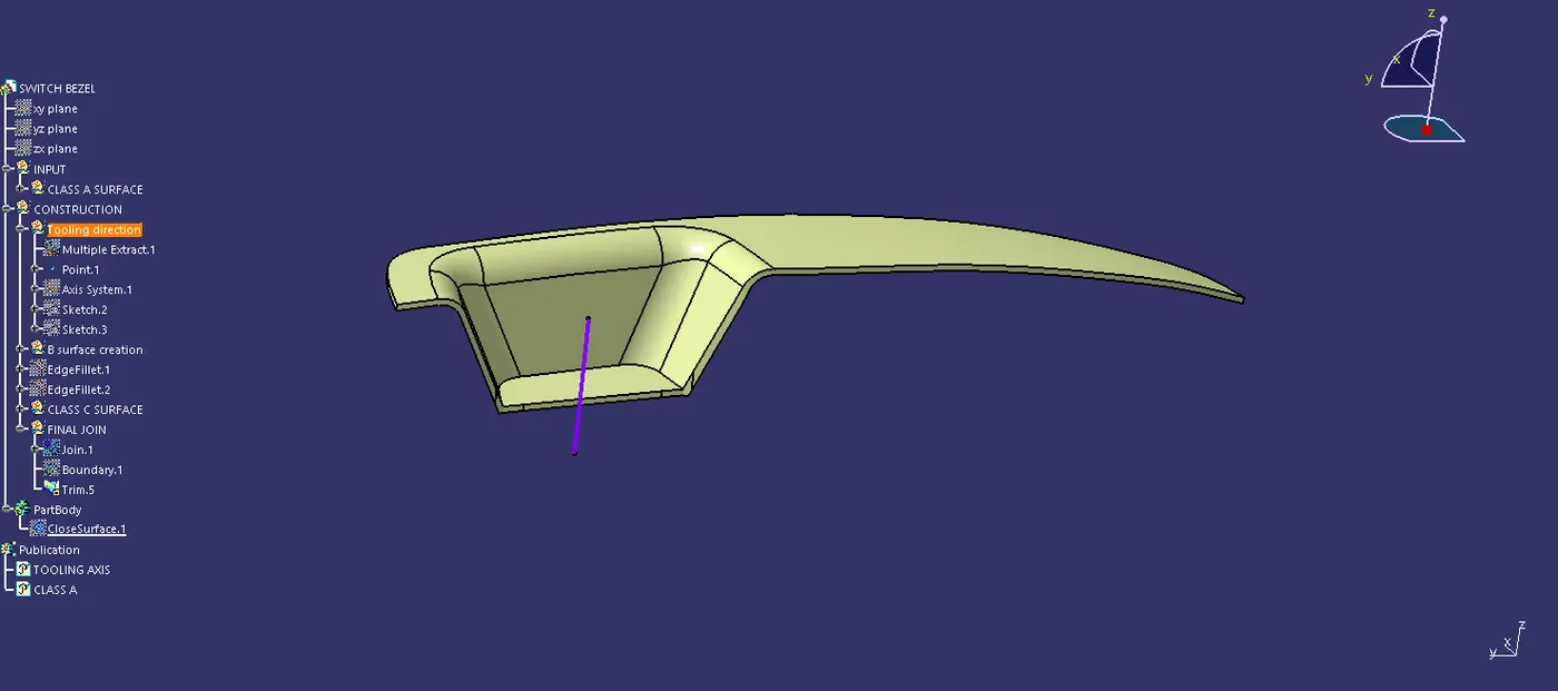
CLASS B SURFACE OUTPUT
The class B surface is created by extracting each surface of the class A surface and then trimming them.
After this, an offset of 3 mm is given in the downward direction to generate the class B surface.
The surfaces are then extrapolated with a certain distance in order to create a cross-section among the surfaces to perform the trim operation.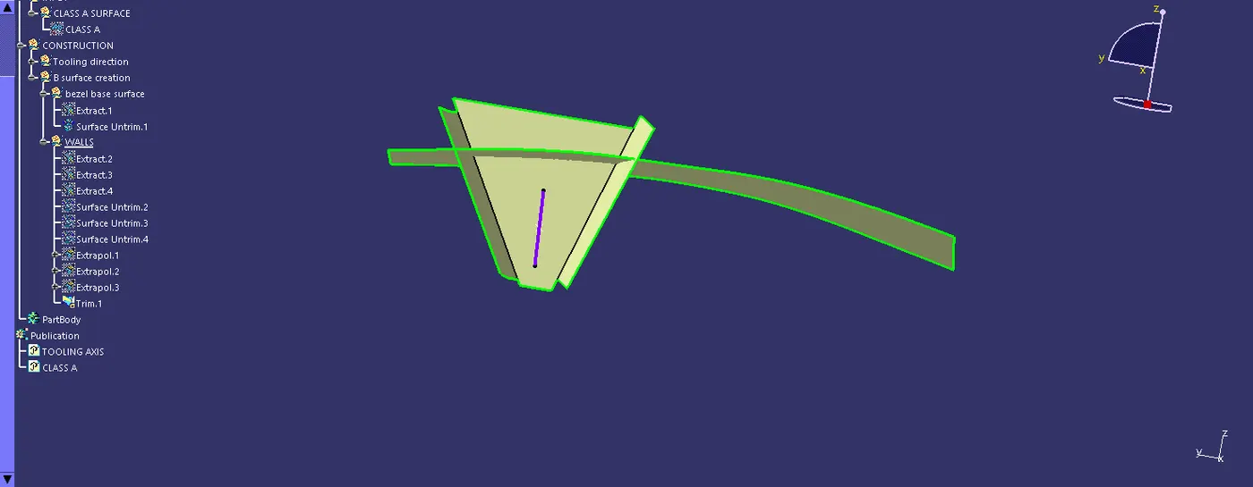
CLASS C SURFACE
Creation of class C surface for a switch bezel
For the creation of a class B surface, first, the boundary of the class A surface is extracted using the Multiple extract feature.
After this sweep option is used to create the sweep along the tooling axis direction.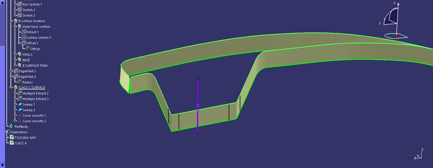
FINAL OUTPUT SURFACE
After this operation, class A SURFACE & class C SURFACE = - CLASS C SURFACE surfaces are trimmed together to give the plastic product a mouldable shape.
FINAL BODY
After ensuring that the surfaces formed are completely closed, the closed surface feature is used to create the solid mould of the switch bezel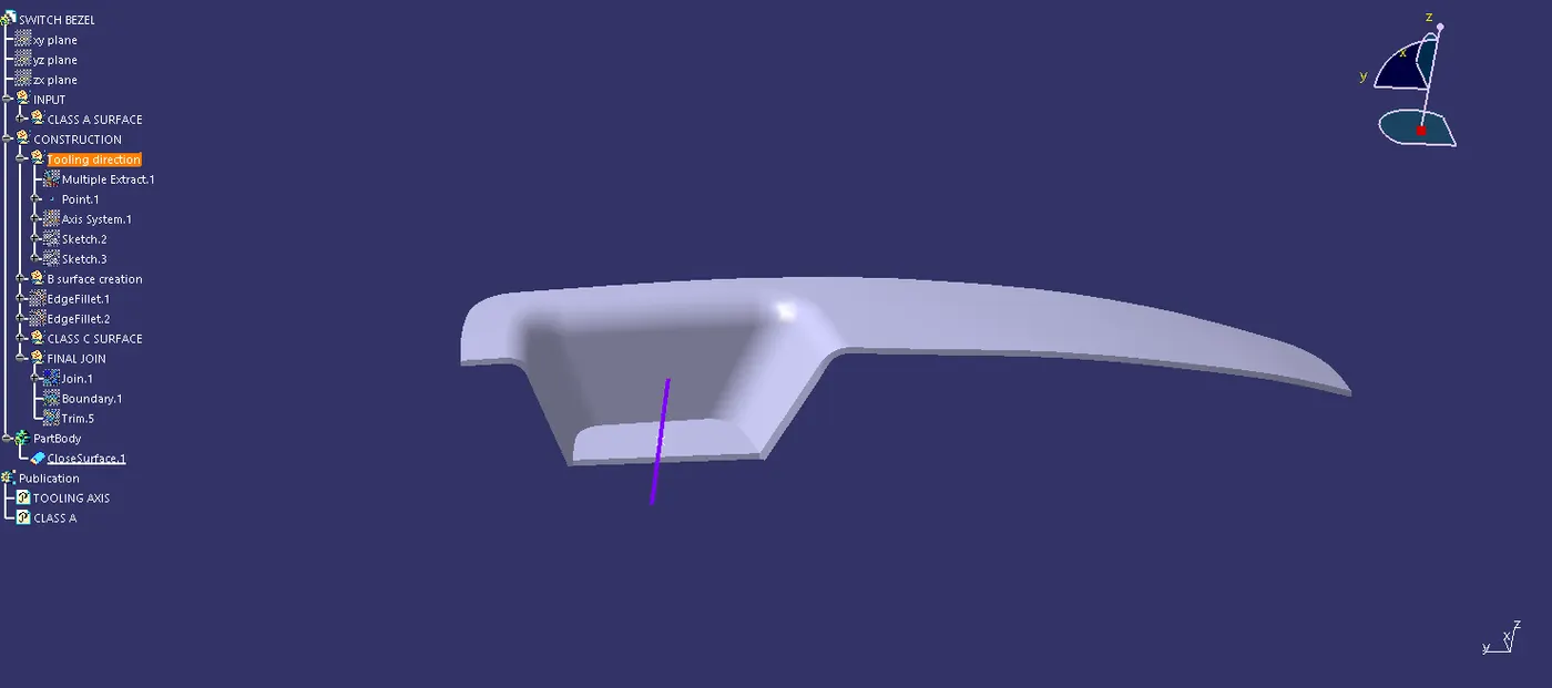
Conclusion
1. Class A, Class B, and Class C surfaces are created following the standards of the automotive industry using Catia V5 software.
2. Draft analysis was performed on the switch bezel and it was observed that the draft was under the permissible limit for the manufacturing of the component using the injection molding process.