Week 11 - Project - A pillar Design with Master Section
RESPECTED SIR,
PLEASE LOOK INTO THE BELOW ATTACHMENTS, FOR REPORT AND CATPART FILE
REPORT ON ‘A_PILLAR_MASTER_SECTION’ WITH DOG HOUSE BASED ON DRAFT ANALYSIS
TOOLING AXIS CREATION:
In order to perform the drafting analysis, the first step is to create the main tooling axis for the given class-A surface. First I have extracted one of the surface patch, which is suitable for creating the main tooling axis. Then created the point on the extracted patch using point type as ‘On surface’ option. Once the point is created on the surface, the next step is to draw the dummy tooling axis. After creation of dummy tooling axis, with the help of axis system insertion at generated point, using intersect command two lines were generated across class A surface as shown in figure. These two lines generated were bisected using the created point and thus main tooling axis is created as shown in figure. Also for more details, refer to the figures mentioned below.
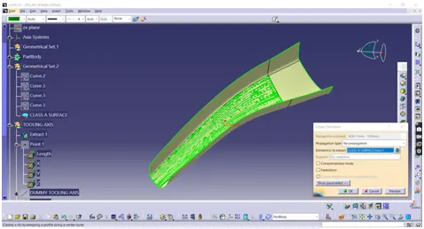
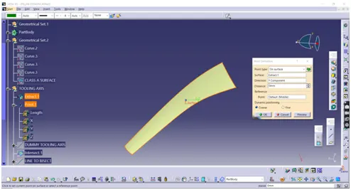
Above figures shows that, point generated on the appropriate patch
using extract and point on surface options
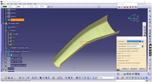
Using intersect option for bisecting the dummy tooling axis
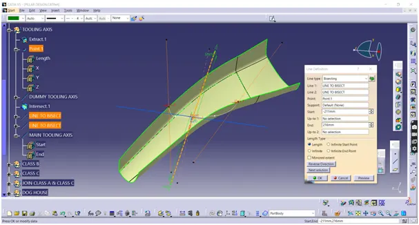
Dummy tooling axis is bisected to generate main tooling axis
Now, once main tooling axis is generated, draft analysis is made on given class A
surface with 3 degree draft. And it was observed that given class A surface is well
designed 3 degree draft.
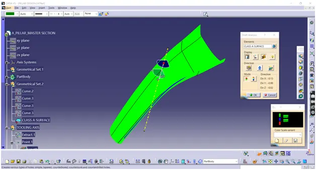
Figure shows draft analysis performed on class-A surface at a draft angle of 3 degrees
DRAFT PRODUCED ON CLASS - C SURFACE USING SWEEP:
Using class A surface, class C surface is generated with the help of sweep. Out of 4 boundaries, two of the boundaries of class A is selected and using sweep option, the angle of draft is given 3 degrees tending towards outward by selecting the option ‘with draft direction’. Also another two boundaries were given sweep at an angle of 90 degrees by selecting the option ‘with reference surface’.
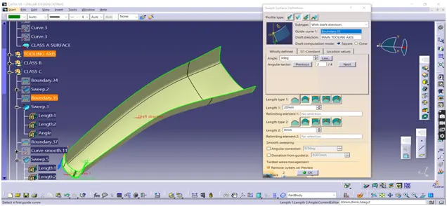
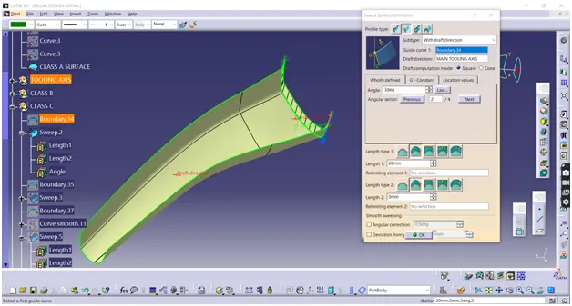
The above 2 figures shows that boundaries of class A surface were used to sweep at an
angle of 3 degree draft in outward direction
DRAFT ANALYSIS ON DOG HOUSE:
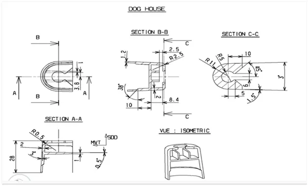
After creating the appropriate sketch or outline of doghouse, it has to be swept in a draft direction at a given angle of 1.5 degrees in inward direction to create a draft, as shown in figure mentioned below.
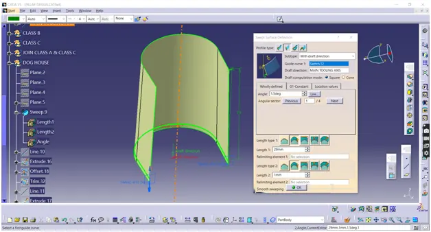
Also using draft command, on the stiffener, 0.5 degree draft is given. This can be understood by looking into the following figure mentioned.
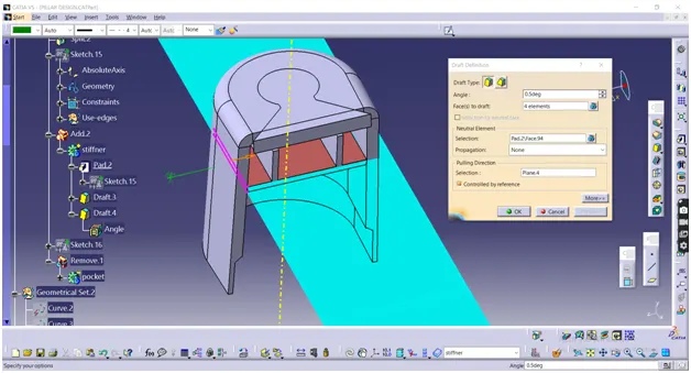
The base with cyan colour represent as stiffener on which 0.5 degree draft is applied
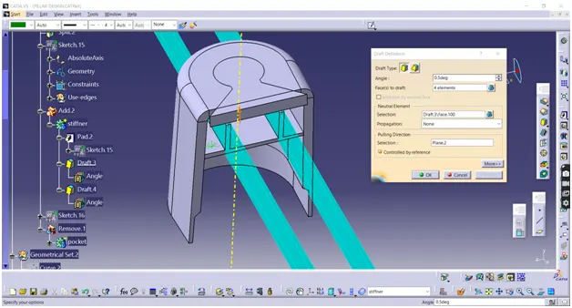
0.5 degree draft is applied to the walls of the stiffener
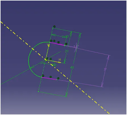
Figure shows the pink coloured sketch, in which, the draft angle
is mentioned about 3 degrees according to the given figure in the
challenge, therefore draft angle is adjusted to 3 degrees as per
given instructions
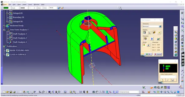
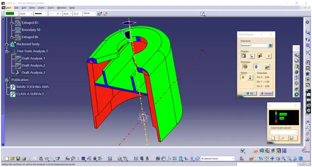
The above figures mentioned shows that, the draft angle of 1.45 degrees is performed
on dog house by selecting the main tooling axis as the draft direction
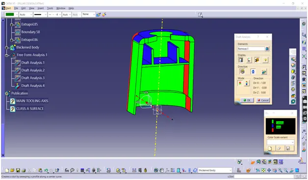
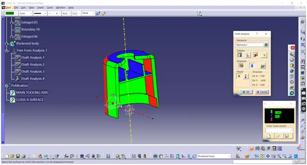
The above two figures shows the dog house where, inner walls are selected to perform
draft analysis at an angle of 1.45 degrees using side core axis
Thus, separately for dog houses also draft analysis is made. First draft analysis done with respect to main tooling axis of pillar, for outside boundaries of dog house. Another draft analysis has done with respect to side core axis of dog house, for inner side boundaries of dog house. Thus according to the design parameters of dog house, it was observed that the draft angle of 1.45 degrees is well suitable and also the designed dog house met the required draft angle as shown in above figure.
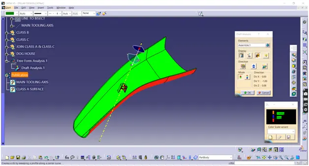
The above figure shows that, draft analysis made on a closed surface with dog house with the draft angle of 1.45 degrees and found that, the given component is well suitable to go for the next step.
NOTE:
Two different figures have given to construct the dog house. In which I have chosen the below figure as the reference and constructed the dog house.
Thanking you,