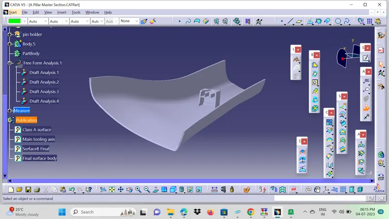
Week 11 - Project - A pillar Design with Master Section
AIM:
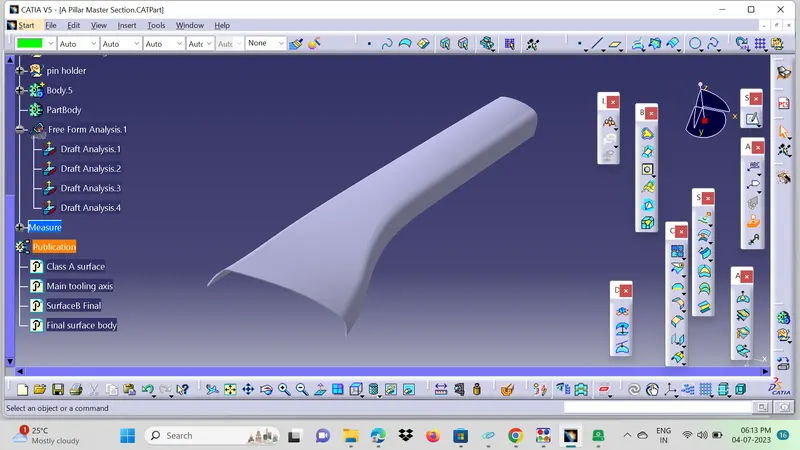
Create the Pillar, Plastic component through the given Class-A surface. To begin with, the tooling axis for the given Class-A Surface should be created meeting the requirements of the draft angle and at the end perform the Draft analysis on the model.
A below image is given class A with master section.
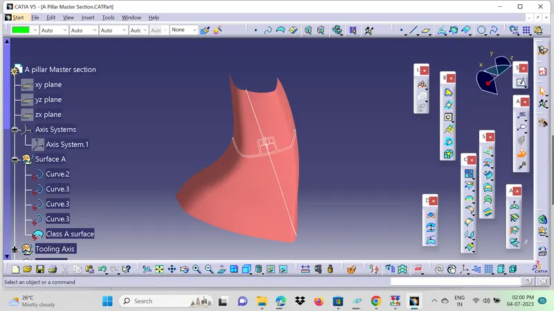
CLASS A SURFACE
Class-A (or 'Strak') is a term used in specifically in automotive design. It describes the final production Class data for the aesthetic parts of the car. The term 'Class A' is often misunderstood, but it's generally seen as the 'Holy Grail' of Class modeling.
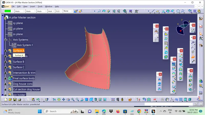
- Since we copy the Class A from the original Class A, then create separate geometric set then paste it. Then join the Class A.
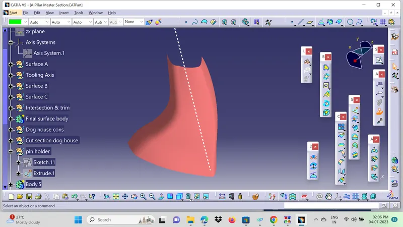
TOOLING AXIS
- Now we create tooling axis for the Class A. First a create axis system for where we want, then we create intersect based on the axis system.
- Extract the bottom surface and insert point on a surface then create lind based on a point.
DRAFT ANALYSIS ON THE CLASS A SURFACE:
Next, We will perform a Draft Analysis on the Class A Surface itself:
Before starting with a Draft Analysis Operation, we will go to the 'Customize View Parameters' option under the 'View Toolbar'. Then we will enter the 'Customize View Mode' where we will go under the 'Mesh' option and select 'Material' and press 'OK'.
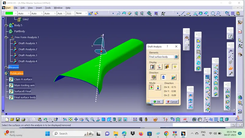
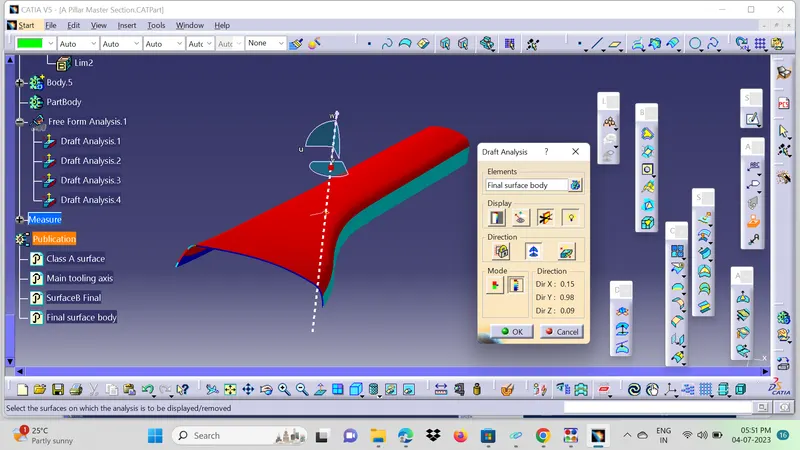
To start the Draft Analysis in the 'Generative Surface Design Workbench', we will go to 'Insert' and then look for the option called 'Analysis'. Once found, we will go under that and click on 'Feature Draft Analysis. This will open the 'Draft Analysis' Dialogue box. There, we will ensure that under 'Mode' we have selected 'Quick Analysis', under 'Display' we will select 'Show or Hide the Color Scale' and then select '3 Degrees' as the permissible draft angle. Then, under 'Direction' we will choose the icon with the symbol of the compass on it which stands for 'Use the Compass to define the new current draft direction'.
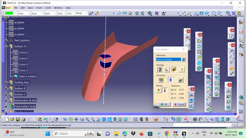
It is evident from the above image that the Draft-Analysis on our Class A Surface was successful and the component is feasible to manufacture.
CLASS B SURFACE
- Now create a class B surface.
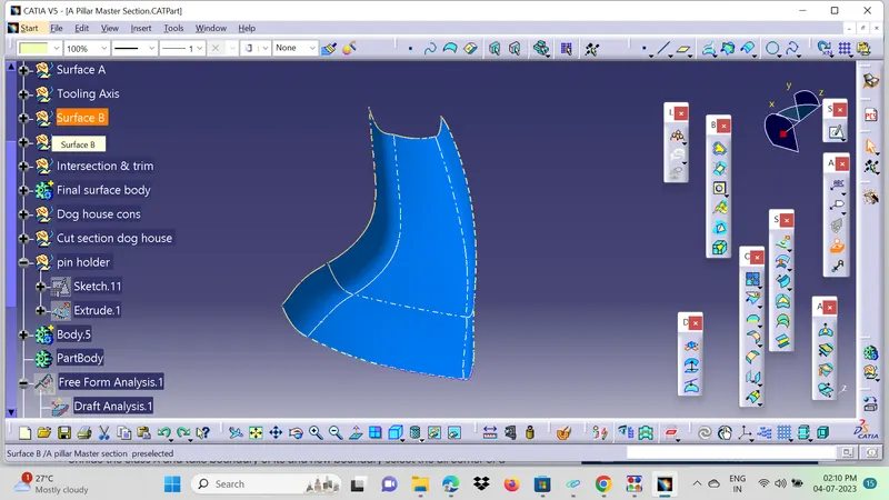
- In class B, first create base of class B from class A. Insert geometrical set define as class B, that is base of class B.
- Use extract command and extract a base from class A. Then use untrim tool get full body of a base. Next use extrapolate tool extended a base , then offset of 2.5 mm.
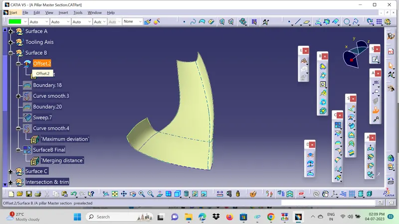
After Repair
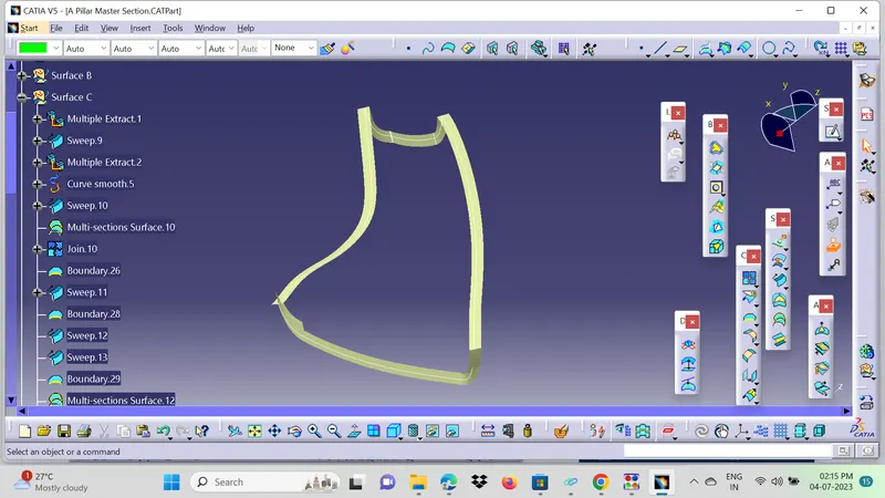
CLASS C
create the surface with swept & multi section surfaces.
FINAL BODY
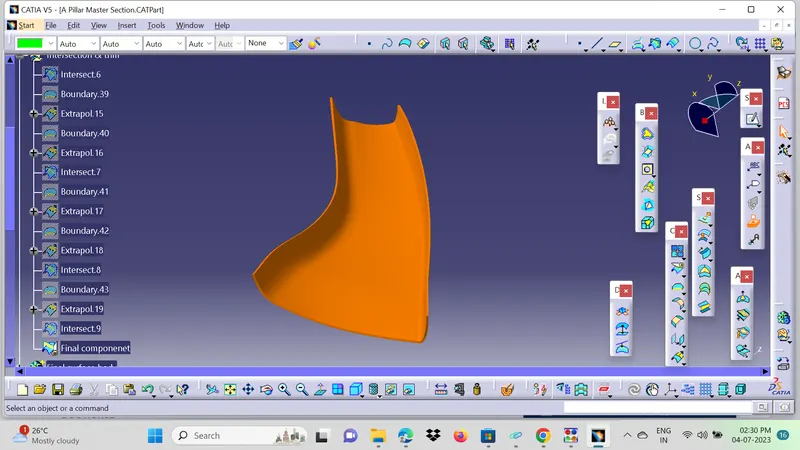
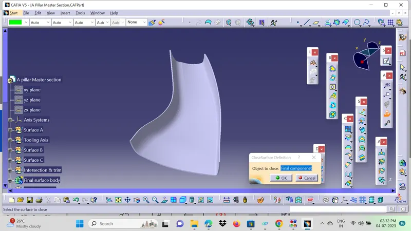
CLOSE BODY
- Go to the part body workbench then use close boby tool and finally get close body of base bracket
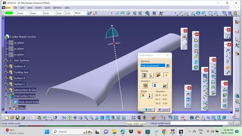
DRAFT ANALYSIS FOR THE CLOSED BODY USING THE MAIN TOOLING AXIS:
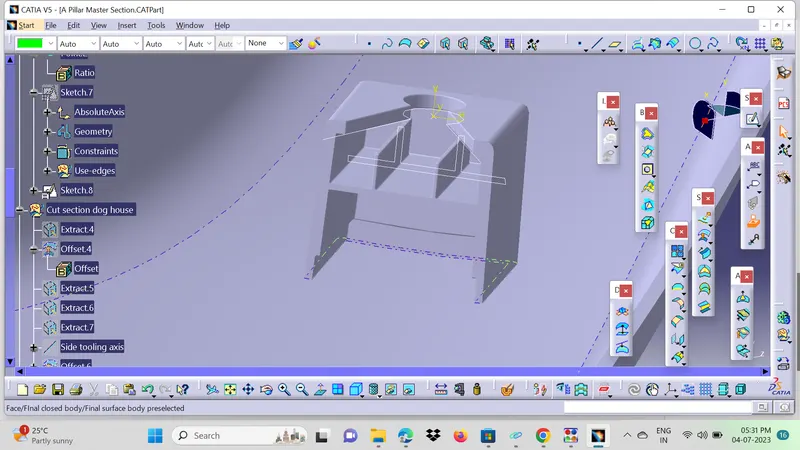
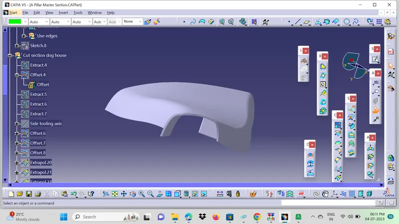
PROCEDURE TO CREATE THE ENGINEERING FEATURE- DOGHOUSE USING THE MASTER SECTION:-
Using the Master Section we can create a sketch that can be extruded to create the doghouse's walls as shown below:
Then, we'll join them all together and move on to the Part Workbench to thicken it by 2.5mm
After that, we're going to provide all the required drafts using the 'Draft Angle' command in Part Workbench.
Draft Angle is provided at both the outer and inner sections of the doghouse with respect to the Main Tooling axis and Side-Core axis respectively.
Then, using the Master Section, we're going to create the inner walls of the doghouse as shown below:
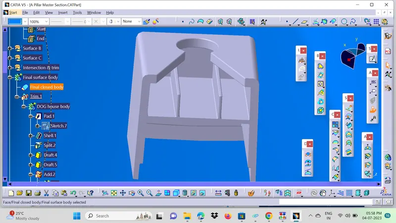
DRAFT ANALYSIS FOR SOLID SURFACE
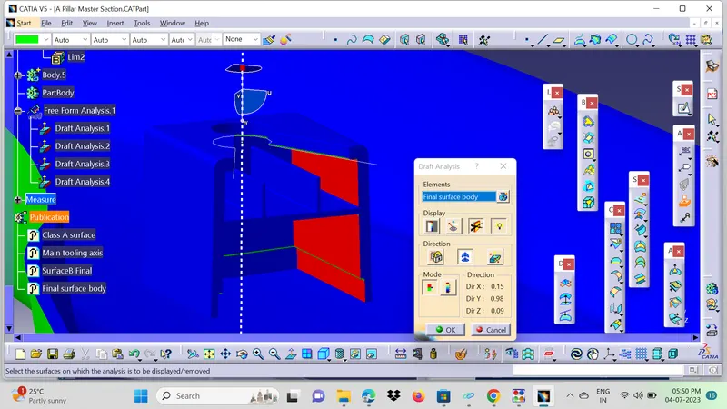
3D VIEWS OF THE FINAL PART WITH PROPER COLOR CODE OF THE DRAFT ANGLE IN VARIOUS ORIENTATIONS:
1. FRONT VIEW:
2. TOP VIEW:
3. ISOMETRIC VIEW: