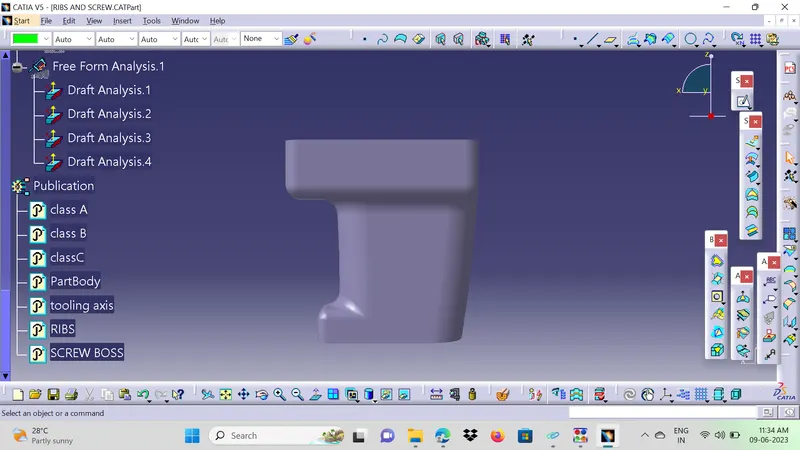
Week 10 - Challenge 1- Attachment Feature Creation (Ribs & Screw Boss)
OBJECTIVE:
Create Closed Body for given Door Handle Class A surface and also, Create the Rib & Screw Boss for the Door Handle considering the design rules.
STEPS FOLLOWED:
- Tooling Axis Creation.
- Draft Analysis of Class A surface.
- Creating Class B surface and Class C surface.
- Creating a Closed body of component Door Handle.
- Draft analysis for Door Handle Component.
- Creating the Sketches of Ribs & Screw Boss profile as per the given guidelines.
- Solid Profile creating for the Ribs & Screw Bosses using Thick Surface and Pad Commands. Added them to the Closed Partbody.
- Given the Draft angle and Edge Fillet Radius to the require faces as per the Guidelines.
- Check the parameters of Ribs & Screw Bosses that were is per Guidelines and standarts.
- Perform the Draft Analysis for Ribs and Screw Bosses Assembly.
Commands used Boundary, Extract, Multiextract, Trim, Join, Sweep, Point, Line, Bisection Line, Circle , Draft, Edge Fillet, Draft Analysis, Closed Body, Thick Surface, Pad, Unitrim, Remove, Intersection.
Key Terms:
TOOLING AXIS:
- It is the direction of Mold's Core & Cavity moves.
- The Tooling Direction is basically the direction that the mold pulls apart.
- The mold is built in two separate pieces, Cavity side & Core side.
- The Core pulls apart from the Cavity and that's the Tooling Direction.
- The Line of Direction or Axis followed is Tooling Axis.
CLASS A SURFACE:
- Class A surface means Visible surface of the Component or part.
- It is the base reference to the creation of B & C surfaces that forms the Component.
- It provides the Aesthetic Appreance to the component.
CLASS B SURFACE:
- It is the mostly the Non-Visible Surface area
- It is the behind the Class A surface .
- It helps in the Parting surface creation.
- Flashes and Missmatches are done in the Class B surface , that will not distrub the Class A surface.
CLASS C SURFACE:
- It connetcs the Class A surface and Class B surface of the component.
- It also describes the Thickness of the Component.
DRAFT ANALYSIS:
- The draft analysis technique is used to analyze whether our part model created is manufacturable or not.
- Based on the Draft condition and Tooling Axis applied, Here the part should get easily removed from the Mold (Core & Cavity).
RIBS
- Ribs are thin extensions that run perpendicular from a wall or plane.
- These used to provide additional support and strength to a part.
- Ribs are used to strengthen the walls of your mould without increasing wall thickness.
- Ribs minimise the problems that come into play when the wall thicknesses have to be increased.
- These also reduce the Defects of wall is too thick, warping and sinking that can result the entire design may need to be rejected.
SCREW BOSSES:
- Screw Bosses are typically used to assist in assembly, as a receptacle for a screw or threaded insert or as the locator.
- Bosses are protuberances on a plastic part designed to add strength, to facilitate alignment during assembly, to provide for fastening, etc.
PROCEDURE:
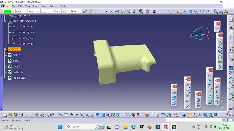
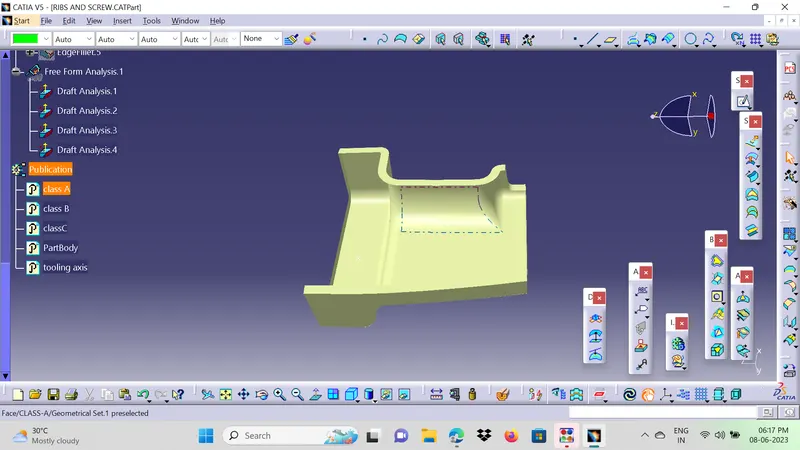
- Checked the Class A surface is a Closed profile by using the Boundary command.
- The complete profile has only one Boundary at the outer edge without breakage.
Checking the given Class A Surface.
TOOLING AXIS:
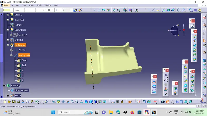
- Checked the all the posibilites of Draft Tooling Axis in all directions so that the most of the surface area visible
- Confirmed that the it would be in Y direction.
- Created a point on Profile and created a line in Y direction as the Dummy Tooling axis.
- Now the Lines are picked from the walls of the Door Handle that are Parllel to the Dummy Tooling Axis.
- Bisecting the Lines with eachother at the Point on surface .
- The formed Bisected Line is Cross Checked as Tooling Axis in the Draft analysis for the Best results.
- The Bisection line that cleares most region and with out Negative Draft angle will be the Final Tooling Axis.
- The Draft Analysis for the Different lines are mentioned bellow
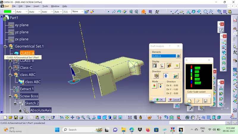
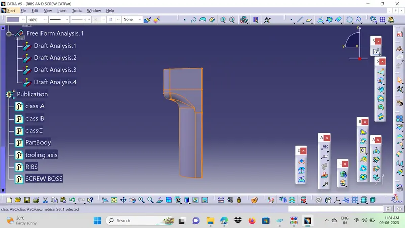
DRAFT ANALYSIS(CLASS A):
- Select into the Material Mode and Insert the Feature Draft Analysis.
- Select the Compass place in the Tooling Axis Direction and Activate the Compass , adjust the compass to the Tooling Axis Direction.
- Provide the Minimum Draft angle is 3Deg or 2.9Deg.
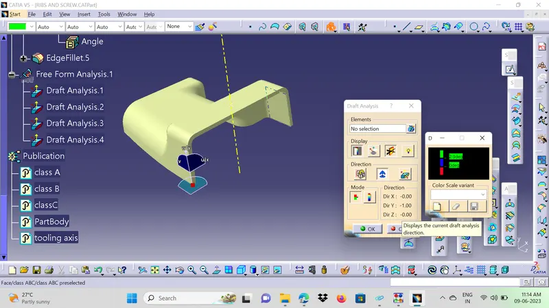
- Select the surface So that the Green Area is more than 3Deg draft angle and it is manufacturable.
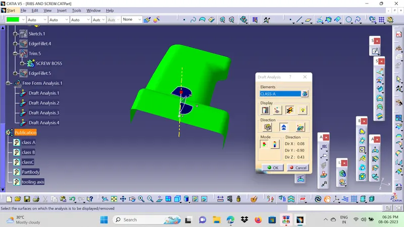
Creating Class B Surface:
Class B surface is mostly the not visible surface and it is the back of the Class A surface.
- Offset the Class A surface for 3mm (Thickness of Component is 3mm).
- The offset surface has the Patches that the minimum fillet value placess cant be offset.
- Checked the posibilites of the Extract the Individuall surface, Untrimed, Extrapolated and trimed them but it is profile is not matching with the base profile.
- Extacted the Complete Profile and the and trimed them but the fillet values are not matched.
- The simple method is done by using the Multi Section Surface.
- Created the Boundary on the Two sides of the profile and Multi-Section Surface command is used.
- The obtained Profile is Joined with the Offset Profile.
- The profile is closed completely with out gap or patches and the edges are formed on it.
- The B surface exterior is Extrapolated in boundary for the Trim with Class A and C surface.
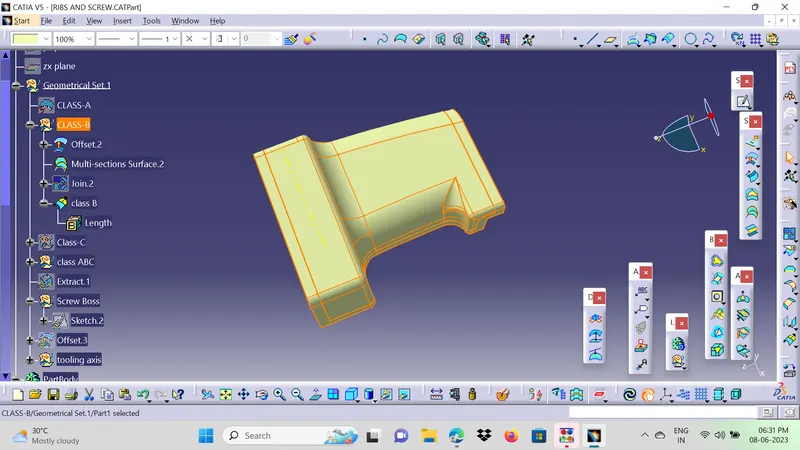
Edges are formed
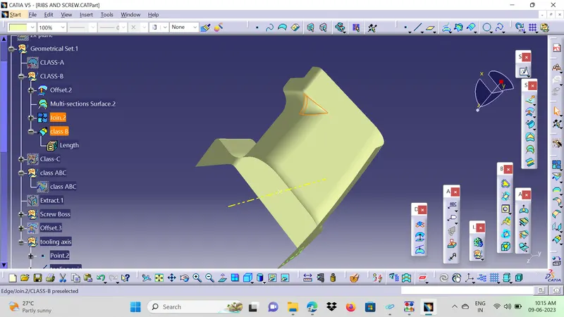
Class C Surface:
Class C Surface is that connect the Class A Surface and Class B Surface.
- Create a boundary on the Class A surface and then Sweep it.
- By using the Sweep Command with the reference of Class A surface and angle of 87Deg to it (the 3deg will give the Draft clearence while manufacturing).
- Then the Class C surface is Joined with Class A surface by using the Join Command.
- The thickness or length of the Class C Surface is 8mm minimum so that it will be trimed easily with Class B surface.
- Now the Joined Class A & C Surace is trimmed with the Class B surface.
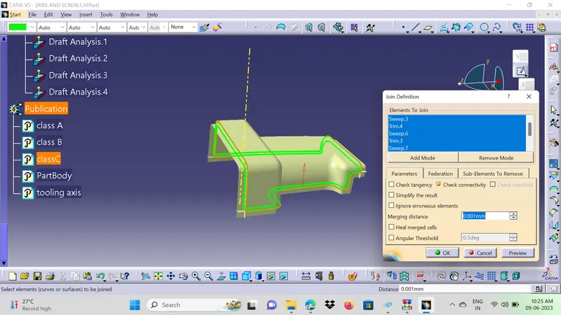
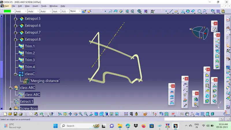
CLOSED SURFACE:
- The Trimed surface is formed.
- Created a boundary on the Trimed Surface so that it inssures that no boundary formed.
- Confirms that it is completely closed.
- By using the Closed surface Command in the Part Body Design to the surface body.
- Now the Solid Body is formed.
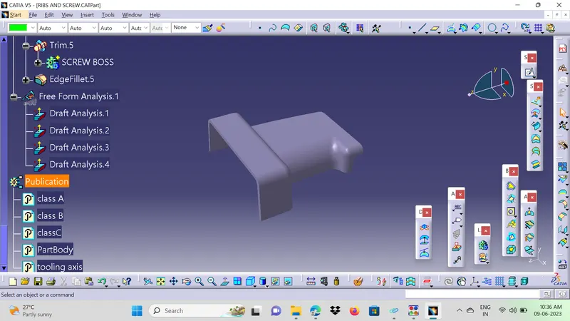
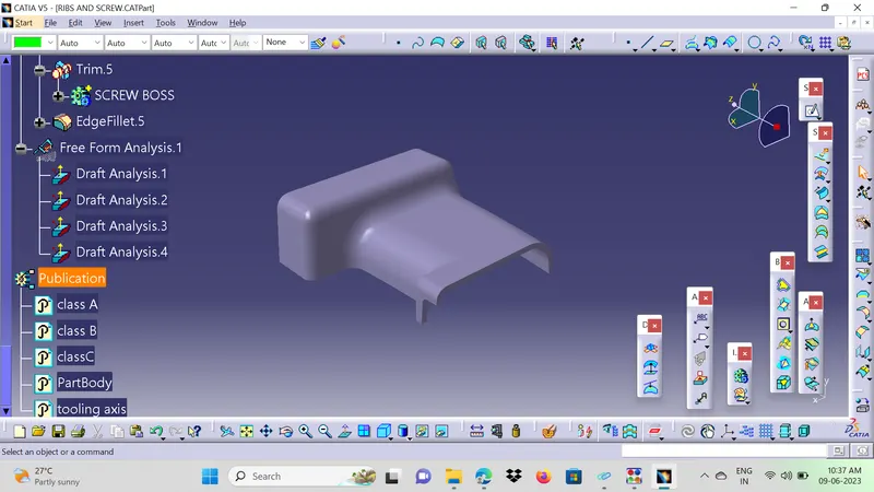
RIBS CREATION:
- Extract the B surface from the Trimed profile.
- Select the Extracted surface as the Reference Plane and Orgin point as the projection point in the Positioned Sketch.
- Create a line on the surface and give the approriate dimensions to it.
- The distance between is also provided to it.
- Now the Lines as the Output Feature for easy acess.
- Extrude the Line in Tooling Axis Direction as a height of 13mm (Height <5*thickness of component, H<2.5*5=12.5).
- By Thicken the Extruded surface at 1mm Thickness by Thick Surface Command in Part Body(Thickness = 40% of thickness of component, =0.4*2.5mm, =1mm)
- Unitrim the Ribs with the Closed Body to remove the Excess Profile at the bottom side on Class A surface.
- Similarly done for the other Rib also.
Design Principle for Rib Creation
-
Ribs are thin wall protrusions that extend perpendicularly from a wall or plane. They are usually found in clusters offering support to a plane that would have otherwise been too thick, but can also be stand-alone support for a single wall. They are commonly used to provide additional support and strength to a part. Thickness and location are essential to rib design.
First, the base surface where the rib has to be created is extracted using the Extract command. A positioned sketch is created and the profile for the rib is drawn.
-
Next, the profile is extruded, to find the height,h=Wall thickness * 5
=2.5*5
= 12.5 mm
Therefore, the height is 12.5 mm
-
The extruded surface is thickened,
Thickness,w=0.4*t
=0.4 2.5
=1mm
Therefore, the thickness of the rib is 1 mm
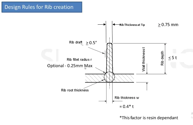
SCREW BOSSES DESIGN:
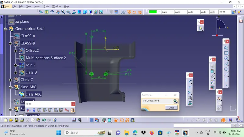
- The circles are Drawn on the Extracted Plane.
- The dimension is taken as the 5mm diameter ie. M6 Diameter is 5.2mm.
- so the outer radius is 5.2+3=8.2mm.
- The Height should be 3:1 ratio diameter to height. the diameter is 5mm so the height is 12mm.
- The Outer and Inner Profiles are Output feature.
- The Both profiles are extraced by Pad command.
- The outer Profile is Added to the Part Body.
- The Inner Profile is Removed to The Part Body.
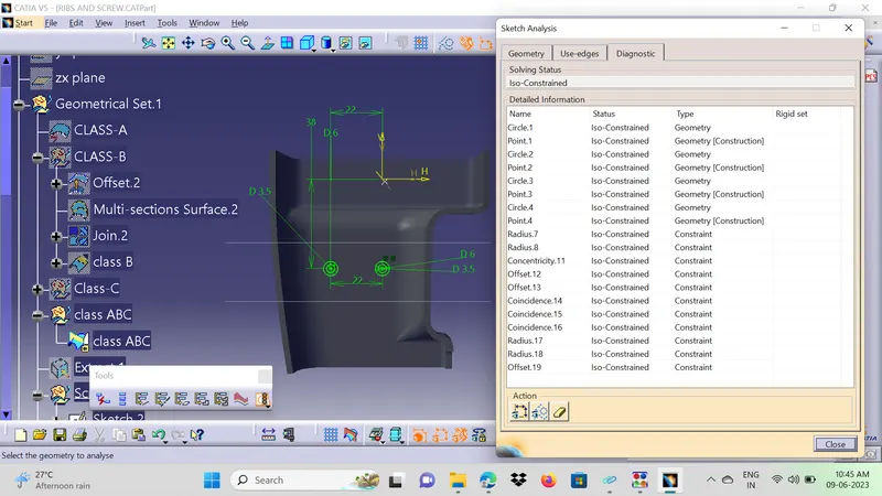
- The Dimensions of the Ribs & Screw Bosses as per the Guidelines are mentioned below.
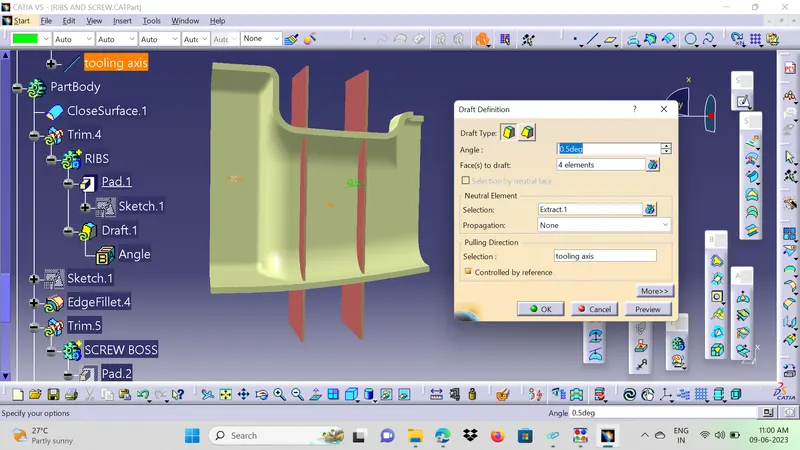
Draft angle is 0.5Deg on Both sides in Upward direction with reference of Tooling Axis Direction
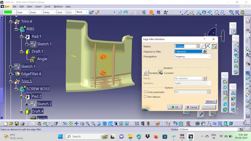
Edge Fillet Radius is 0.25mm
DRAFTING ANALYSIS(FINAL OUTPUT):
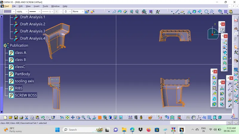
VIWES:
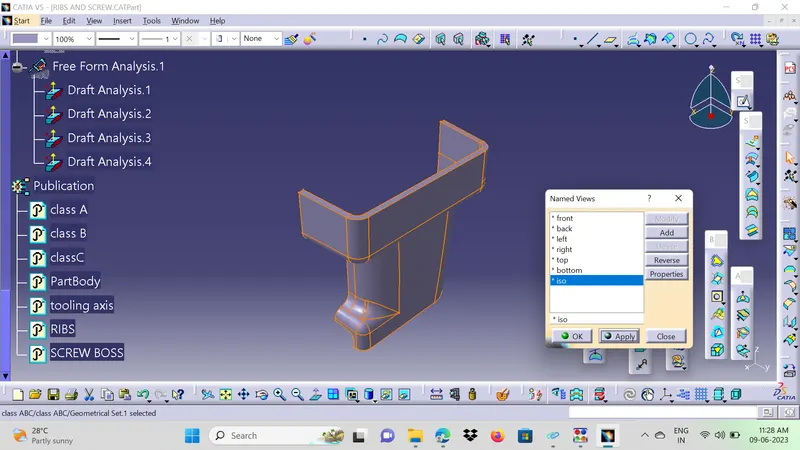
ISOMENTIC VIEW:
SIDE VIEW:
TOP VIEW: