Week 11 - Project - A pillar Design with Master Section
A-Pillar Design with Master Section
Aim -
- Create the A Pillar Plastic component through the given Class-A surfac
- Design features according to themaster section and according to the design requirements.
- Perform Draft analysison the class A surface and the final part.
Provided Data -
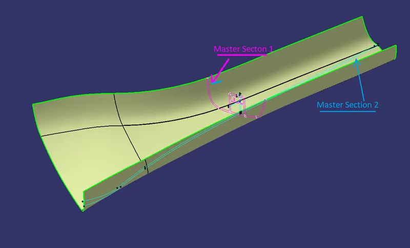
Introduction -
A-Pillar of a vehicle is located at either sides of the front windshield. They also hold the door hinges and are very crucial for the safety of passengers and for structural support/rigidity of the vehicle body. A-Pillars always blocks a part of the driver’s vision and thus creates blind spots. Thus the thickness of the A-pillar is a very important factor all-together and it’s design must be so that equal importance is given to strength, safety and driver’s vision.
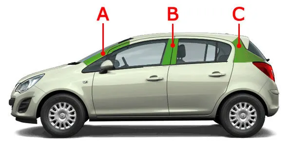
Design of A-pillar -
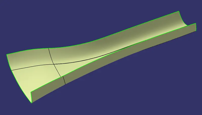
- Check the given Class A surface for any discontinuities. Ensure that there are n gaps, if any errors are found repair them and create a good Class A Surface.
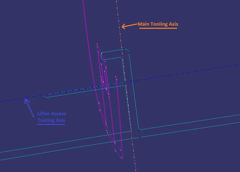
- Create the Main Tooling Axis with the given master sections as reference.
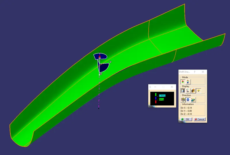
- Conduct the Draft Analysis of the Class A Surface.
- Using the given Master Section as reference, create the Class B surface by offsetting the Class A by the required amount.
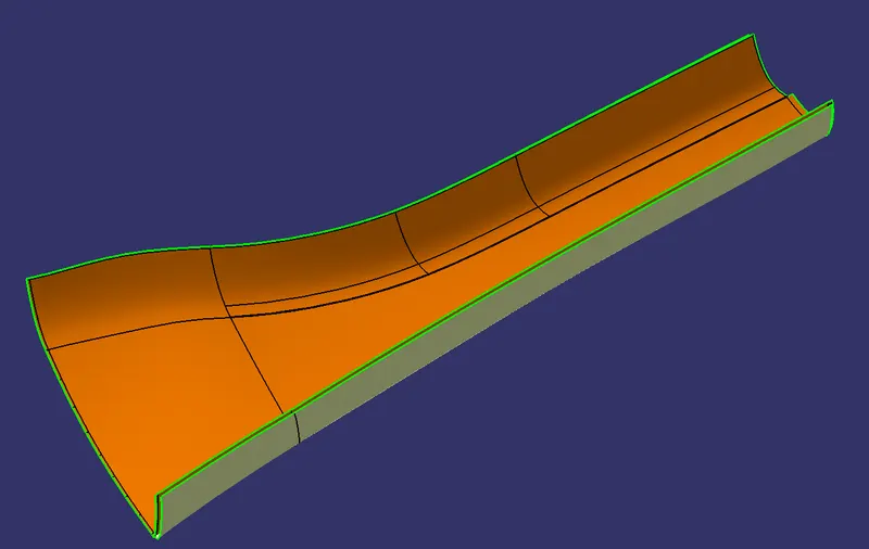
- Check for discontinuities on the Class B Surface and repair the errors, if found.
- Create the Class C surface by using sweep command on the boundaries of the Class A Surface. Extract the boundaries into smaller more manageable boundaries to avoid errors and self-intersections.
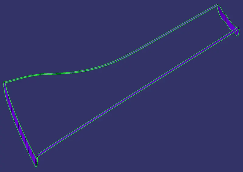
- Join the Class A and Class C surface together.
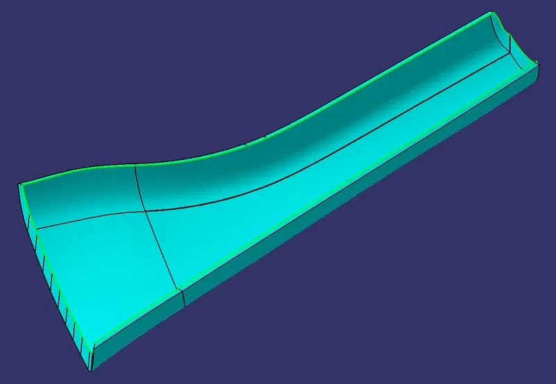
- Extrapolate the Class B Surface so that it intersects with the Class A&C joined surface.
- Trim the Class B surface with the Class A&C Join to form the Hollow Closed Surface.
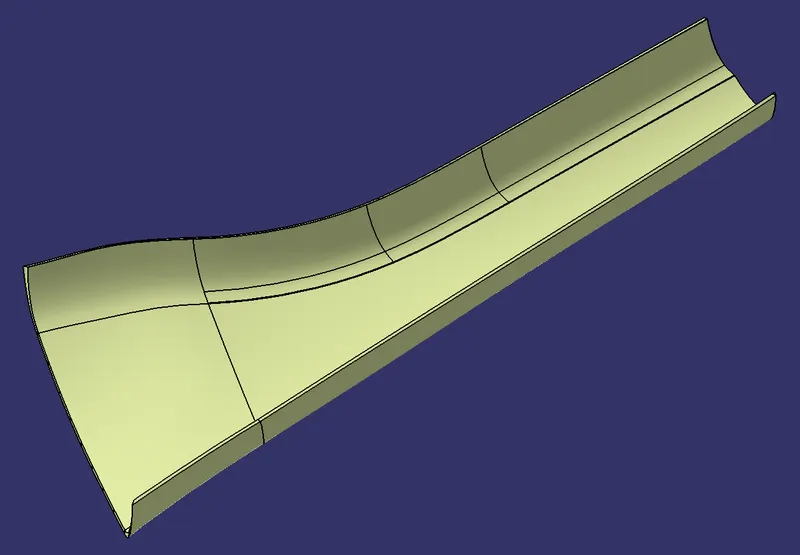
- Use the ClosedSurface command in part workbench to create the solid part body for the A-Pillar.
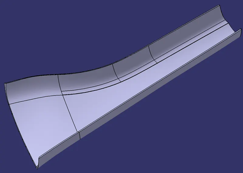
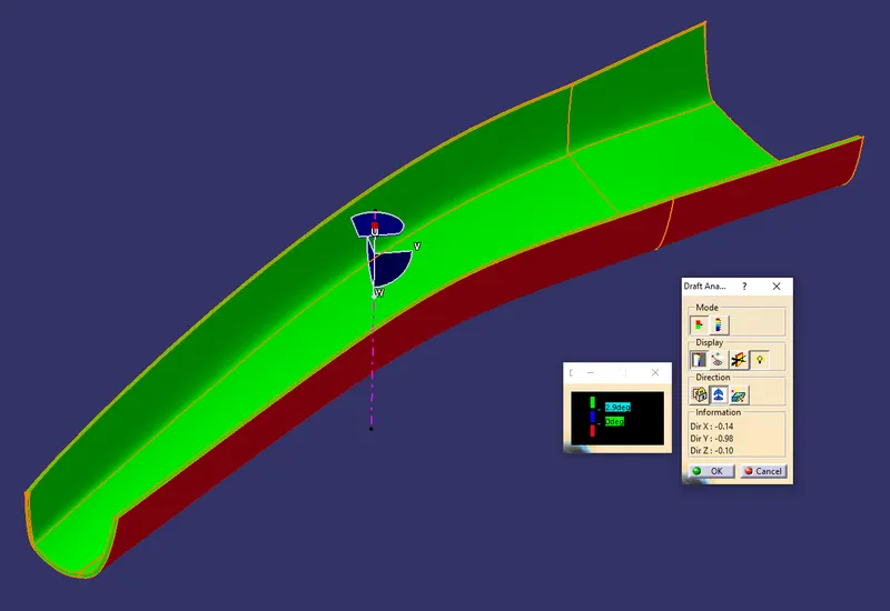
- Conduct Draft Analysis on this A-pillar Partbody.
Design of Engineering Features -
- Use the given Master Section to determine the location of the Dog House and other features.
- Create the Core access Tooling Axis with reference to the Dog House’s walls and the given master section.
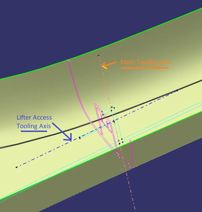
- Create an iso-constrained & positioned Sketch of the profile of the Dog House.
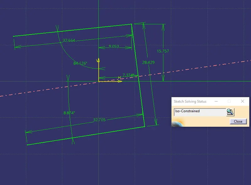
- Extrapolate the profile with reference to the Master Sections.
- Trim using surfaces extrapolated from the edges from the master section.
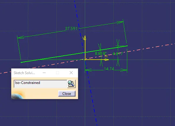
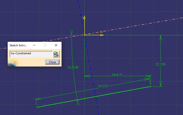
- Thicken the surfaces and provide required draft to the outside faces with reference to the Main Tooling Axis.
- Provide edge fillets on the outside and inside of the Dog House.
- Create a Sink-mark prevention feature on the Dog House, using faces extracted and Offsetted, using the Split command.
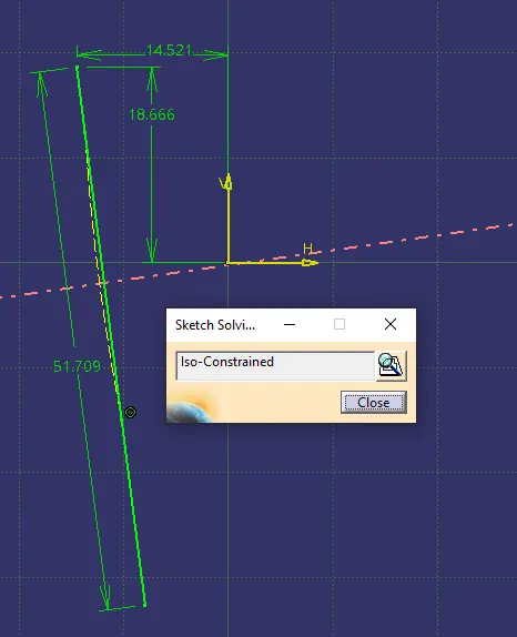
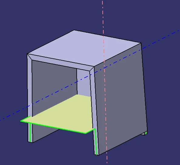
- Design the additional engineering features on the Dog House in a positioned iso constrained sketch (i.e, The Cross Surface in the Dog House , the Ribs positioned on the cross surface and the Screw Boss on the Top surface).
- Add the Cross-Surface to the Dog House.
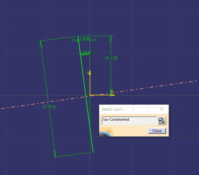
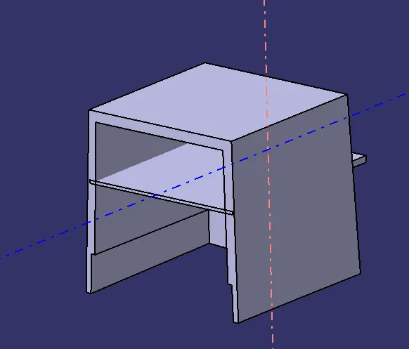
- Remove the Screw Boss Area from the top surface of the Dog House.
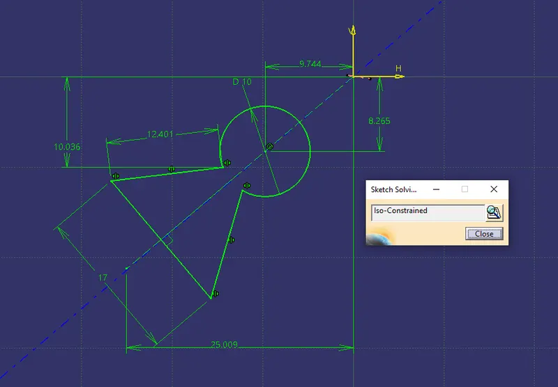
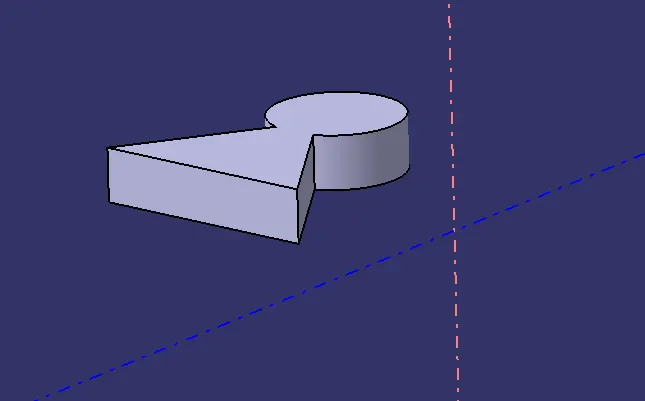
- Add the Ribs to the Dog House.
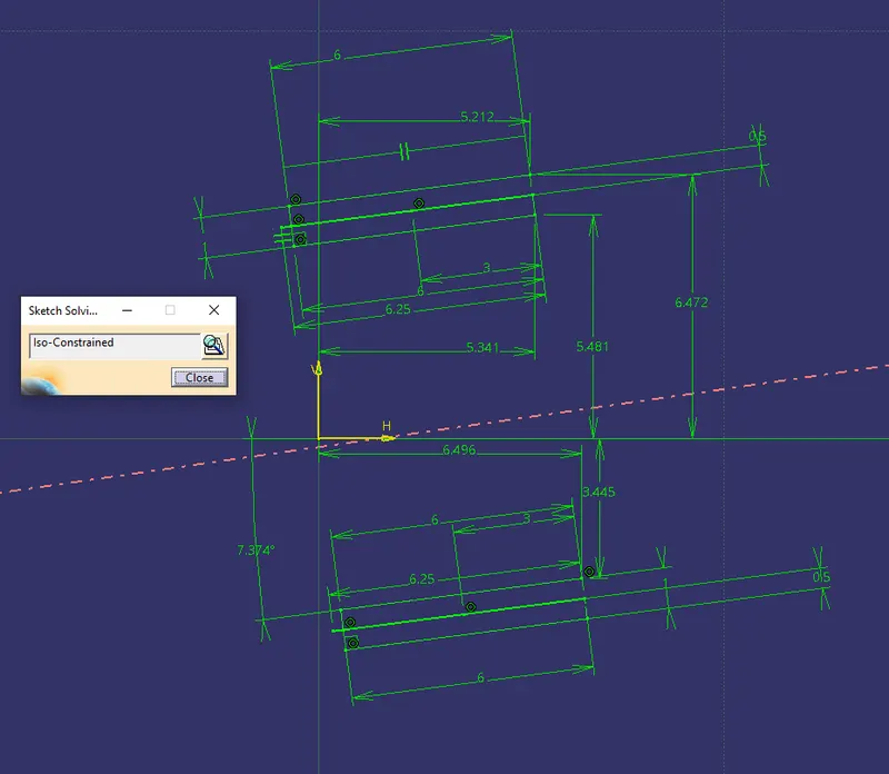
- Thicken and add fillets to these surfaces . Also add draft to the faces according to the Side core Tooling Axis.
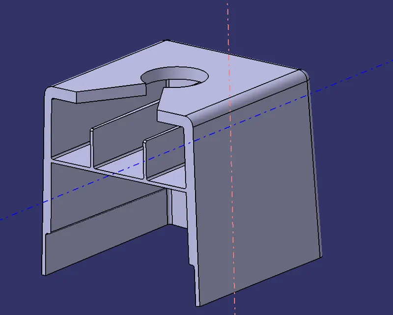
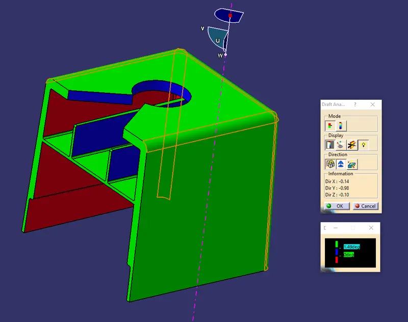
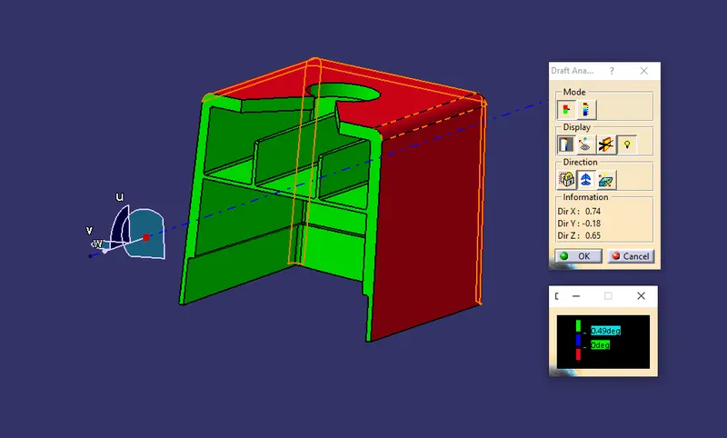
- Conduct the Draft analysis of the part with respect to both the Main Tooling Axis and the Side-core Tooling Axis.
- Union Trim the Engineering feature to the A-pillar partbody to get the final component and provide fillets to the edges.
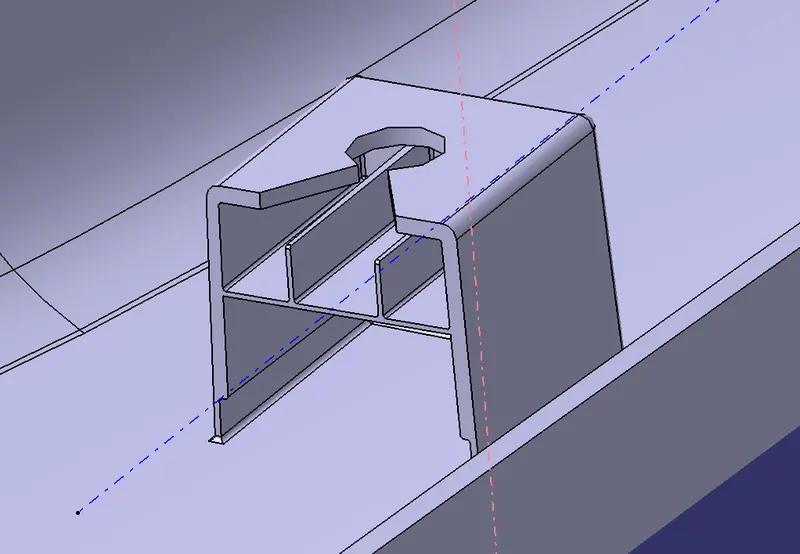
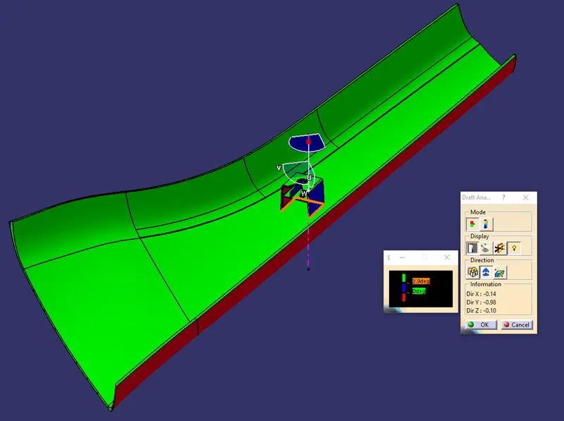
- Also perform a Draft analysis of this final Part with the Main Tooling Axis as reference.
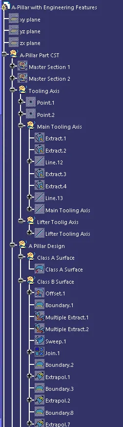
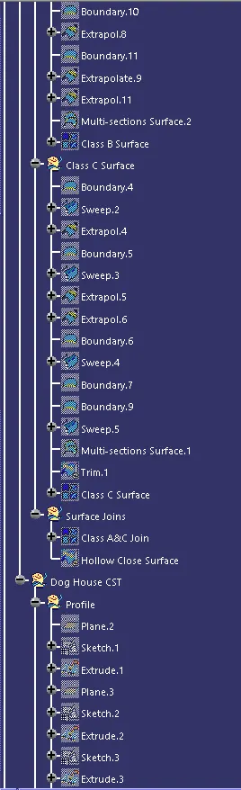
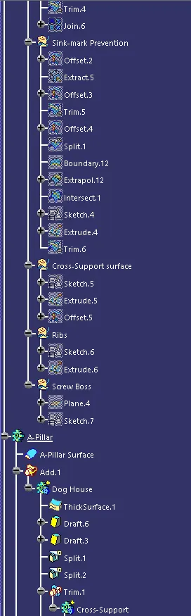
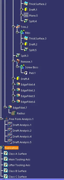
Tree Structure -
Draft Analysis -
Class A Surface :
A-Pillar Solid Surface :
Engineering Feature
- With respect to the Main Tooling Axis:
- With respect to the Lifter Tooling Axis :
Final Part :
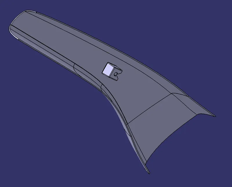
Final Component Views -
Isometric View :
Side View :
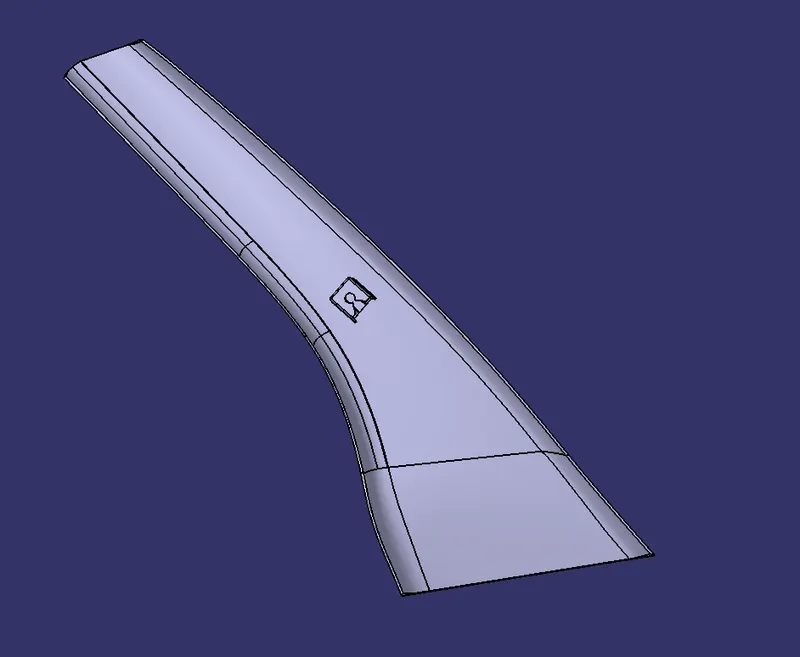
Front View :
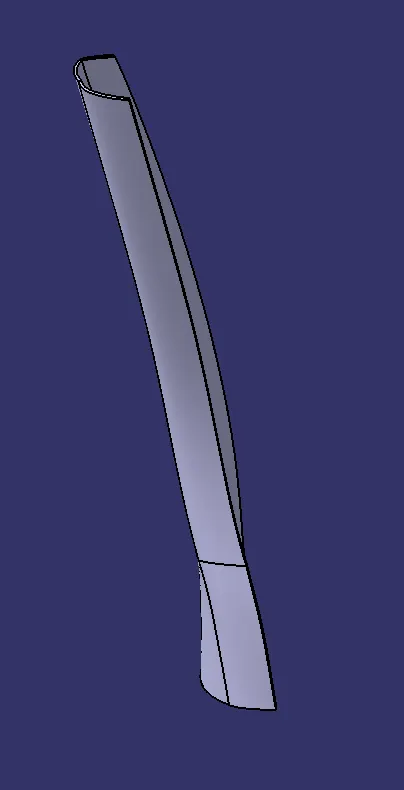
Top View :
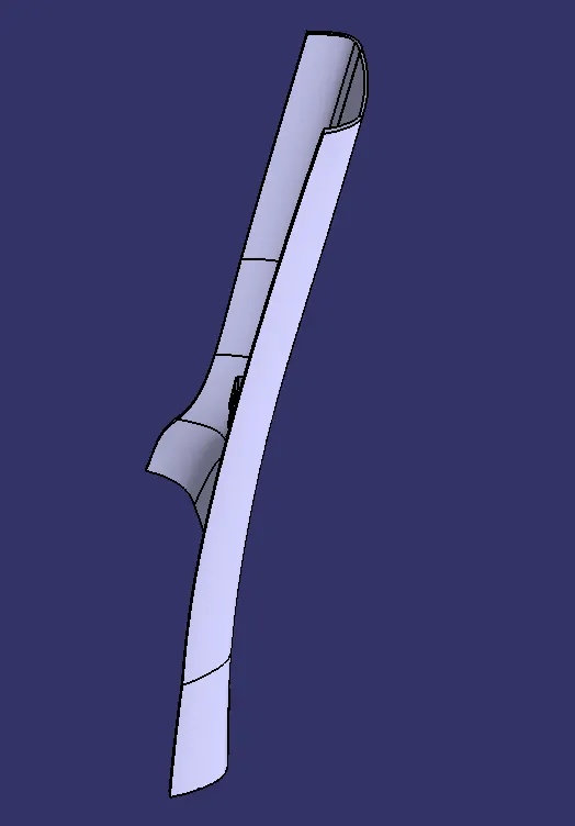
Result And Conclusion -
- The A-Pillar Plastic component is designed fromthe given Class-A surfac
- Engineering features are Designed according to themaster section and the design requirements.
- A Draft analysisis performed on the class A surface, the Engineering feature and the final part, all passes the inspection.