Week 11 - Project - A pillar Design with Master Section
Purpose of master section: The master section helps you to decide the feasibility, clearance, packing, and fixation strategy of a component before working it in 3D.
Detailed report:
Method followed:
- Creating a tooling axis to perform the draft analysis.
- Creating a Class B surface from a given Class A.
- Creating a Class C surface and Plastic component by Close Surface.
- Making a B-side features: Dog house
- Performing a draft analysis from the side core (Lifter) axis and main tooling axis.
Procedure:
1. Creating a tooling axis to perform the draft analysis :
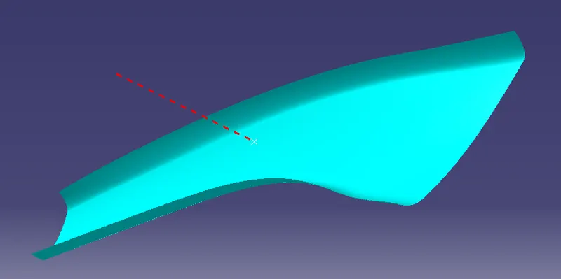
- In the given Class-A inputs we also have the Master section
- From this, I creat the mid point of them one line wich is i extrcted separatly and aftre using POINT & DIRECTION commond i creat final tooling axis
2. Creating a Class B surface from a given Class A :
- To create a Class B surface from Class A,
- First, we offset Class A for 2.5mm given the thickness value.
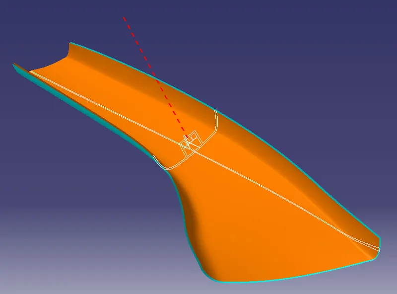
We cant face any difficulty to offset class A surface by value 2.5 mm because fisrt we correct the class A surface and after we creat a B surface by offseting the modify class A surface. We can see some pictures of modified class A surface in belowe image.
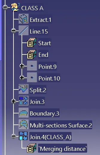
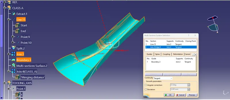
We can see in above images the some surface which creat a error during offset so first we solve that problem by using MULTI SECTION commond we craet a new perfact surface and after join that surface with given class A surface and we get our final class A surface..
3. Creating a Class C surface and Plastic component by Close Surface :
For creating a Class C surface, we need to Extract all the outer boundaries and make those boundaries curve smooth of curvature continuity to avoid problems while sweeping.
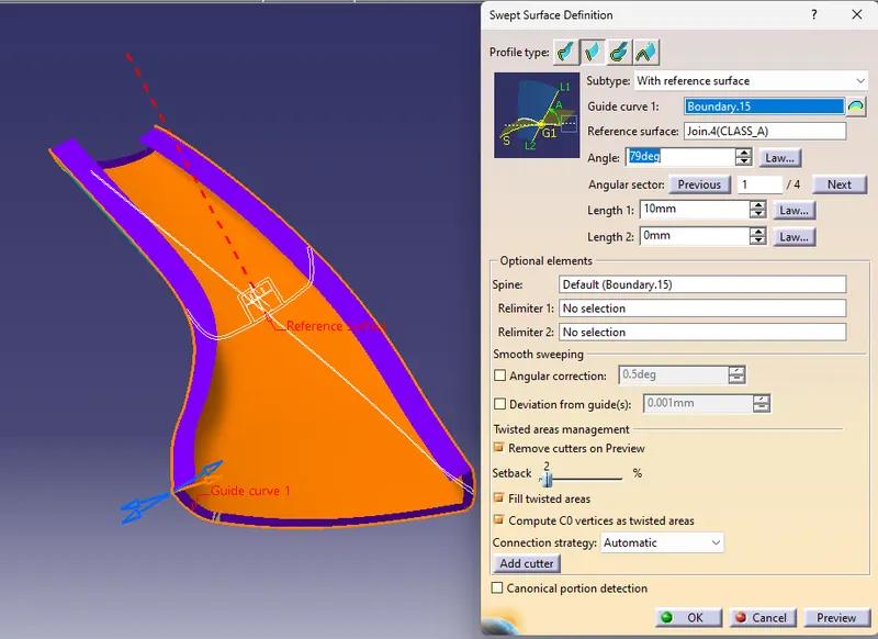
After complete this we need to extrapolet class B surface for trim or split purpose so extraploted class B surface shown in below imgae
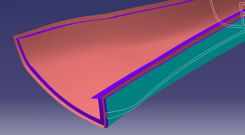
Join all the Class C surfaces to the Class A surface and then Final trim it to the extended Class B surface.
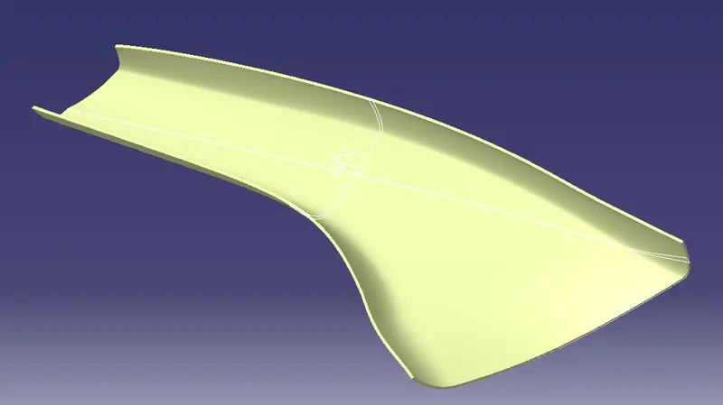
After that, go to the par workbench and make a closed body by close surface feature.
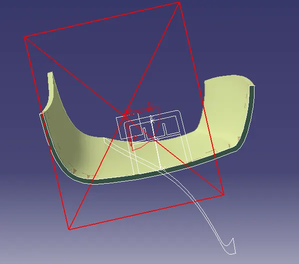
SOLID BODY FOLLOW THE MASTER SECTION
4. Making a B side features :
1. Dog house
It is a ‘doghouse’ looking embossment for screws to attach one piece of plastic to another one. For example, you have a bumper cover, and you want to add a garnish to it. You would use doghouses to do so.
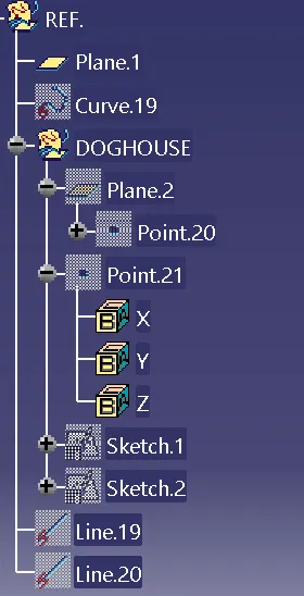
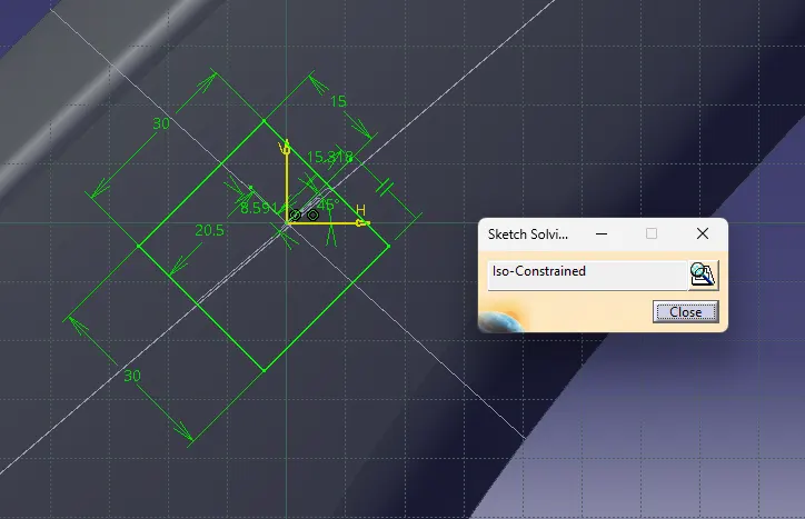
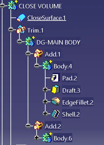
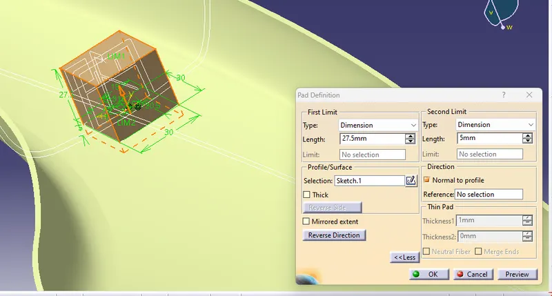
Creat one base solid part as dog house dimention given in master section and that skethc also fully constraint and after complete this we give draft 1.5 degree to three face with respect to tooling axis.
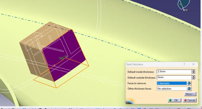
The above image sghows the shell body.
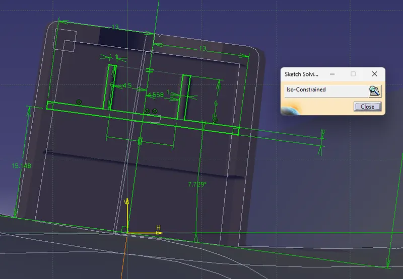
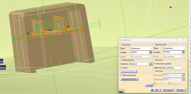
This is a sketch for extra feature in dog house and after it is extruded accridung to master section dimention.
Avoid sink marks: The inner walls of the box are extracted and offset by 1.2mm to the outer side in a shape generative workbench.
Then, the base A surface intersects with the dog house's vertical back surface to get the lines that will be cut out and this profile can easily be covered with a side core or lifter axis.
This profile is extruded and later trimmed with the offset surface to get the final lower cut out. Lastly, the cutout surface is split with the thickened dog house to obtain the final dog house.
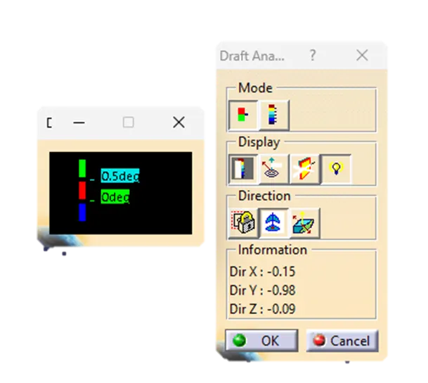
Then, the fillets and draft angle of 0.5 are provided to the dog house. But the inside surface of the dog house is drafted in the direction of the side core tooling axis.
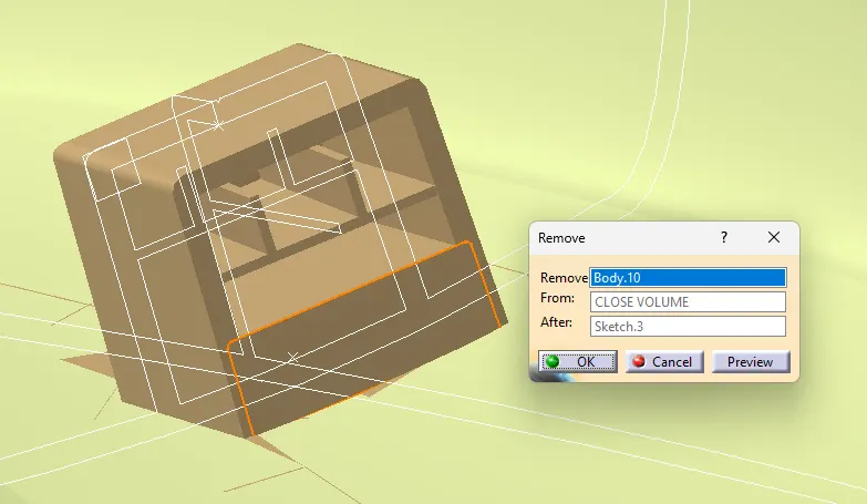
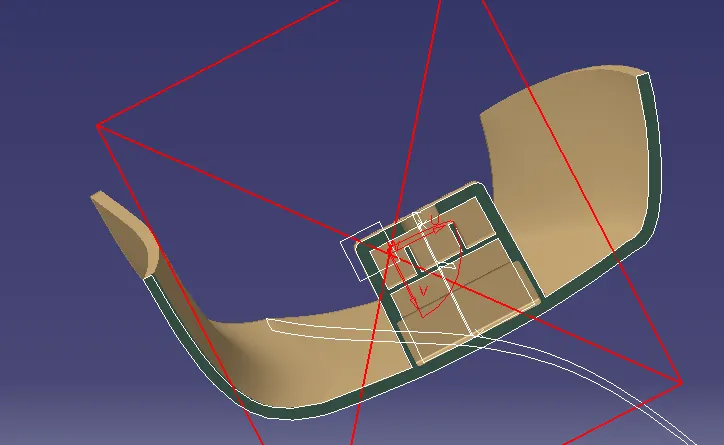
DOG HOUSE FOLLOW THE MASTER SECTION.
5. Performing a draft analysis from the side core (Lifter) axis and main tooling axis :
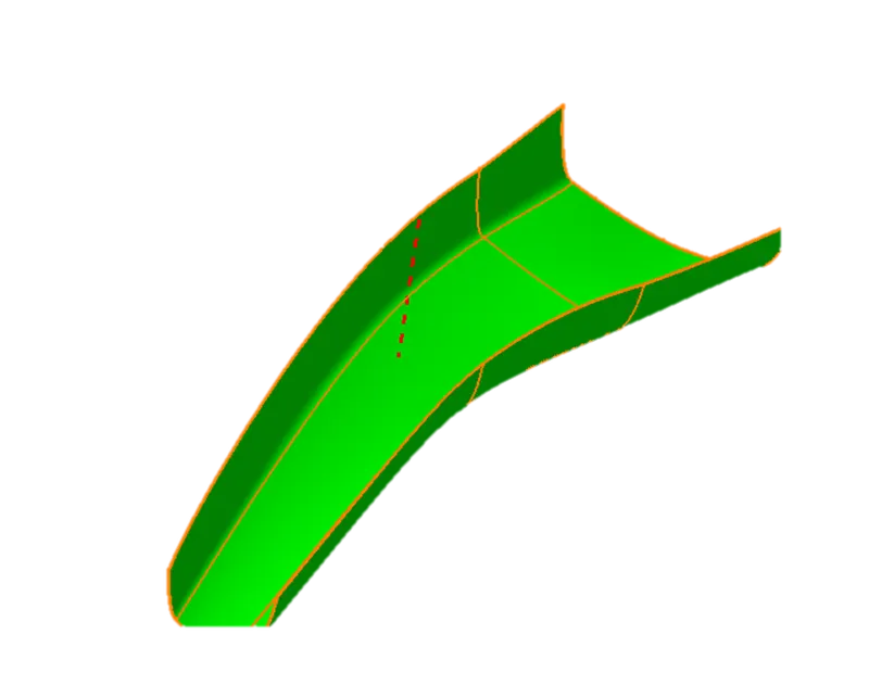
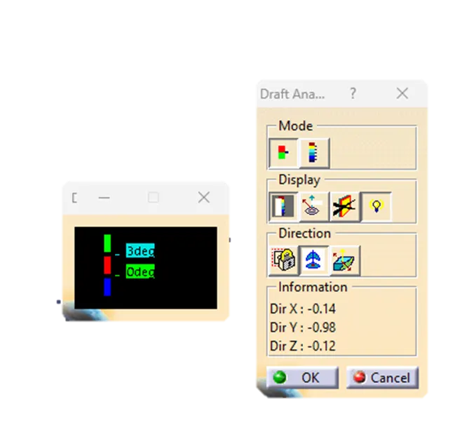
CLASS -A SURFACE
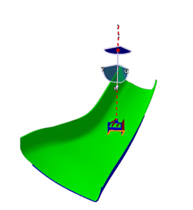
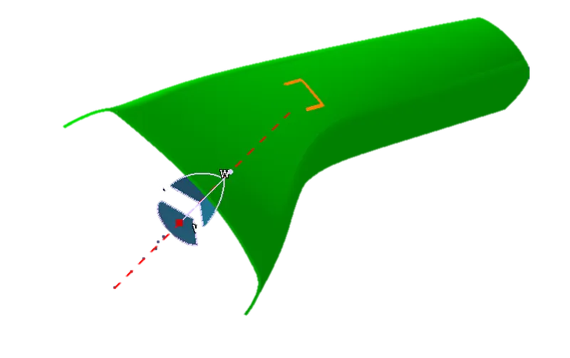
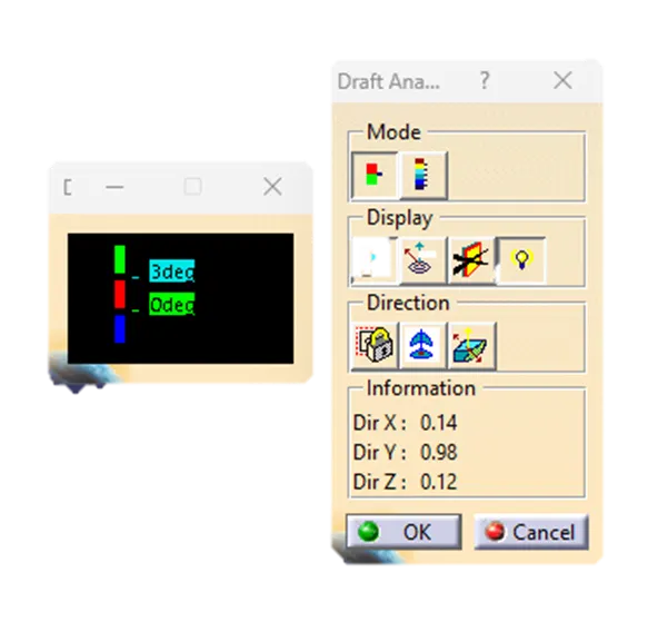
CLOSE VOLUME
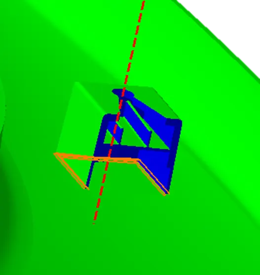
DOG HOUSE-TOOLING AXIS
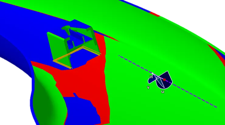
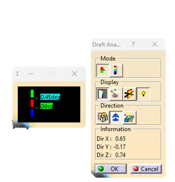
DOG HOUSE- LIFTER AXIS
NOTE:-
DRAFT ANALYSIS INFORMATION BRIEFLY EXPLAIN IN DRFAT ANALYSIS (ppt.)