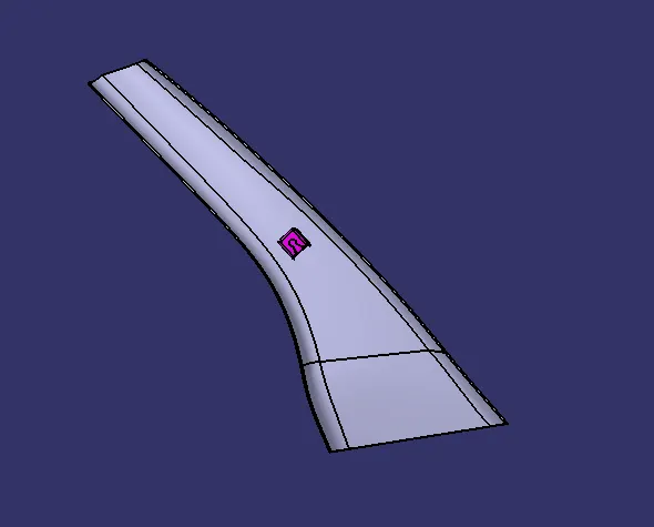
Week 11 - Project - A pillar Design with Master Section
AIM:
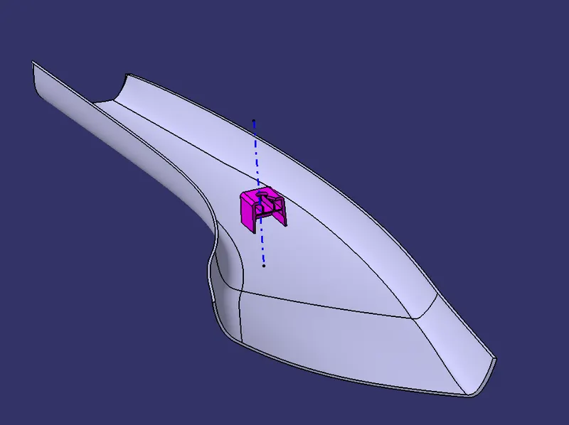
To Create A pillar Design with Master Section using Class A surface as an Reference & master section scketch then doing an draft analysis to the solid part
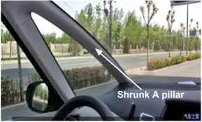
REFERENCE 01
CLASS A SURFACE:
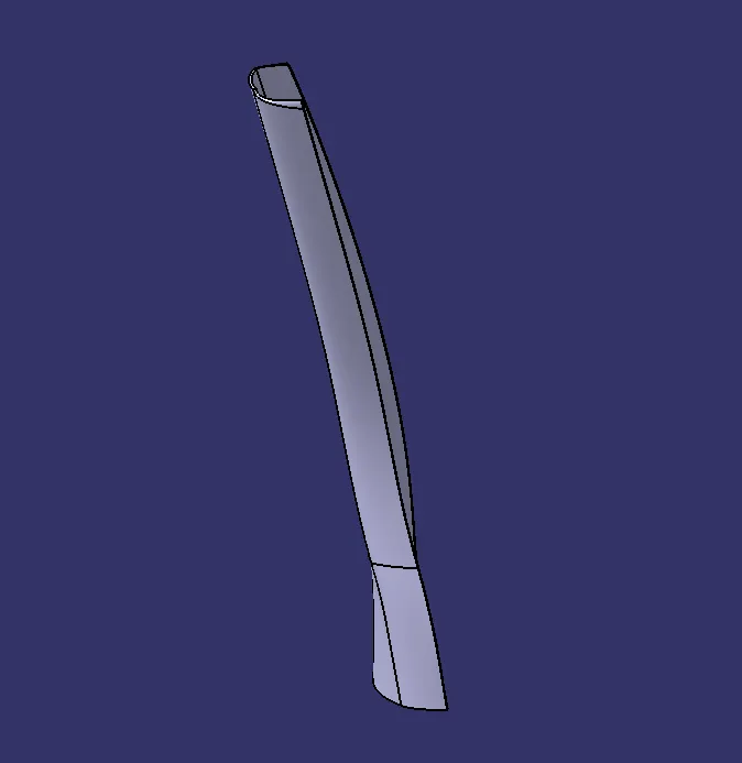
In an automotive design application Class A surfaces are created on all visible exterior surfaces , they have 0mm thickness surface which are given as reference to to create B side features
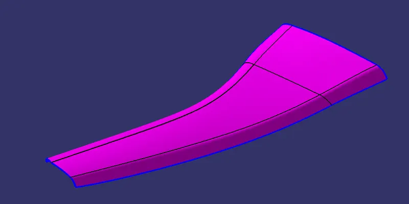
No need for any rework to be done in CLASS A SURFACE
REFERENCE 02 :
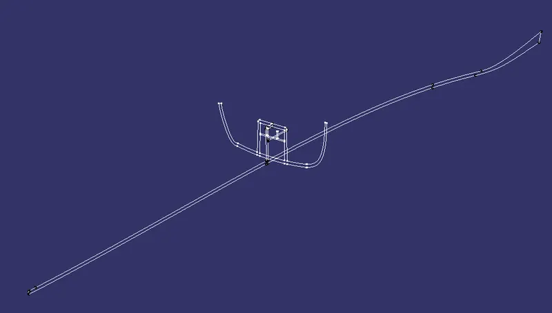
MASTER SECTION :
Master sections are the guide sketches for design requirement for fixiation or other B SIDE feature design
CREATING AN TOOLING AXIS :
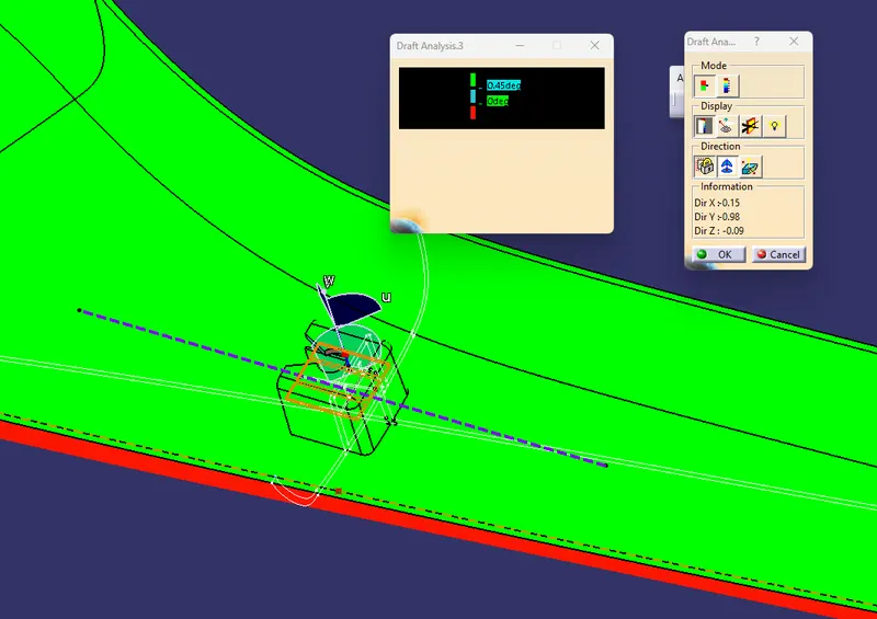
We create an tooling axis to mainly perform DRAFT ANALYSIS and to understand design Manufacturing feasiablity
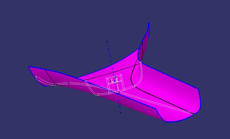
MAIN TOOLING AXIS :
Main tooling axis can be created using BI SECTING LINE METHOD
By using dummy tooling axis we can create correct tooling axis using bisecting line method, by using two lines from dog house in the master section we are gonna create an bisecting line this will be the main tooling axis
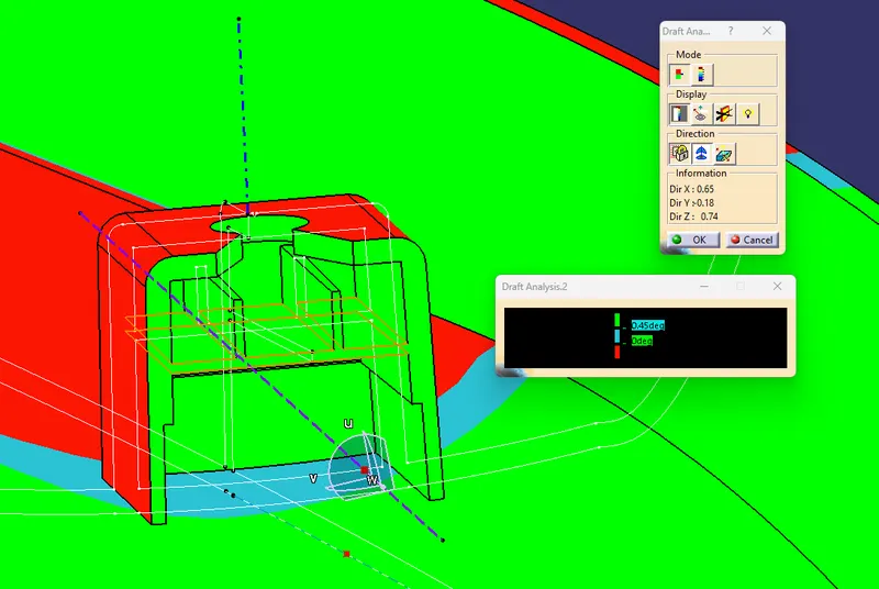
SIDE CORE TOOLING AXIS :
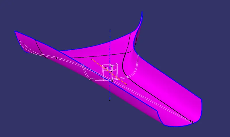
SIDE CORE: The molded side hole or the undercut part must be made into a movable movable core. And the movable core is taken out before the plastic part is pushed out. Then take out the plastic parts. The mechanism for accomplishing these actions is called a side core
SIDE CORE TOOLING AXIS CREATION : Just create and point in inside face of the dog house the create and line by using Y direction
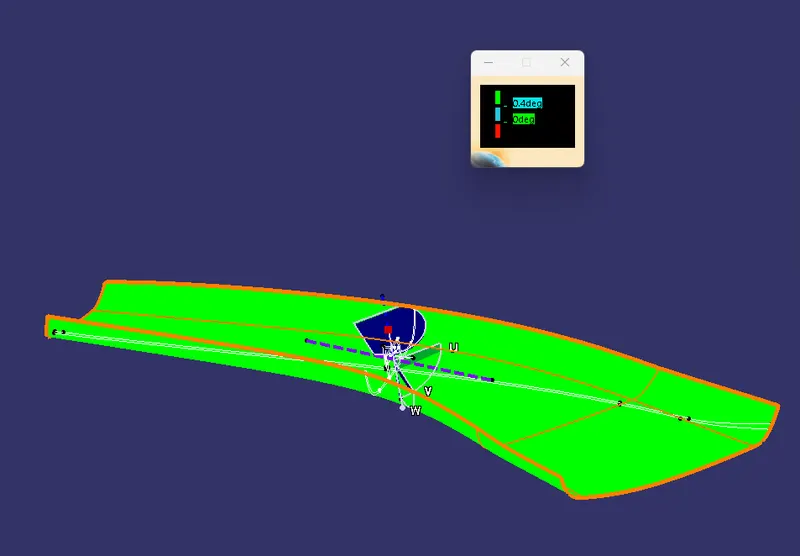
INTIAL DRAFT ANALYSIS
CLASS B SURFACE CREATION :
Just create an offset of CLASS A SURFACE for 2.5 mm
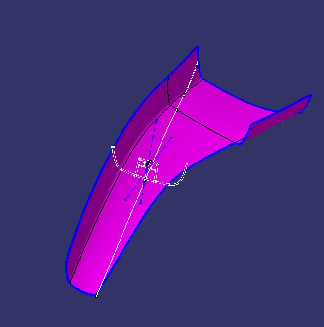
REWORK Need to be done for patch missing
By using SWEEP feature (sweep with reference surface) rework this patch then JOIN feature with the rest of the surface
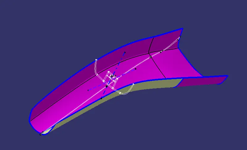
CLASS B SURFACE:
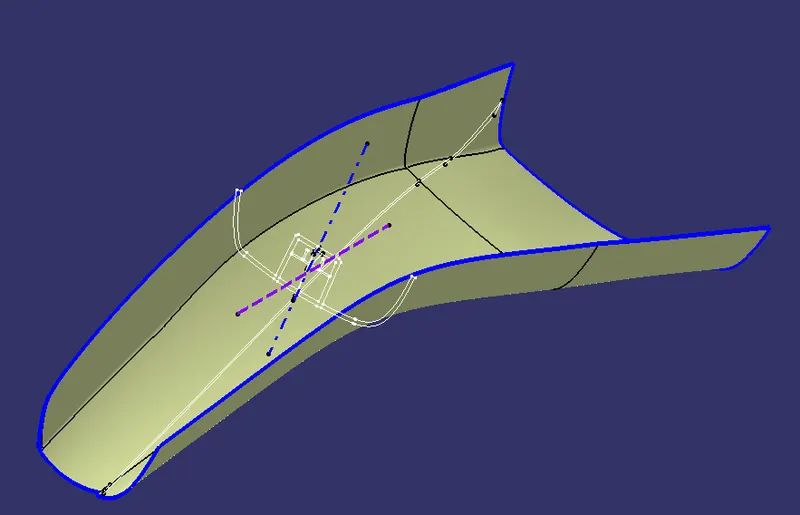
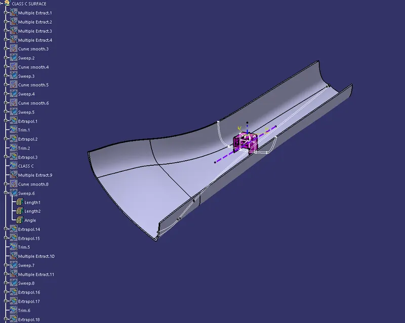
CLASS C SURFACE CREATION:
TO JOIN CLASS A surface and CLASS B surface we use CLASS C SURFACE
To create CLASS C SURFACE WE USE SWEEP COMMAND on all the boundaries of the CLASS A surface
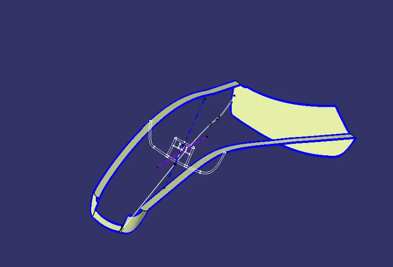
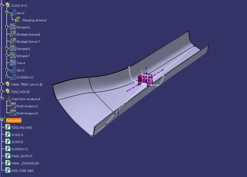
CLASS ( A+C) :
Using JOIN feature join the CLASS A surface with CLASS C surface
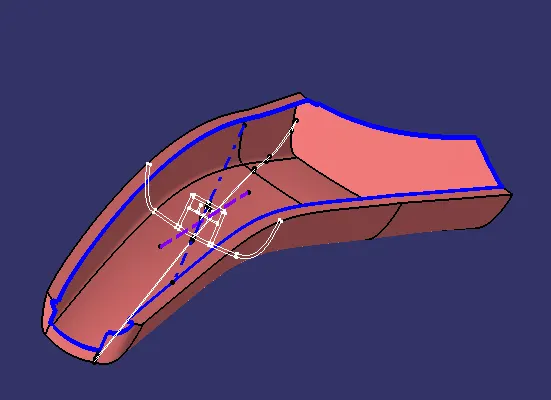
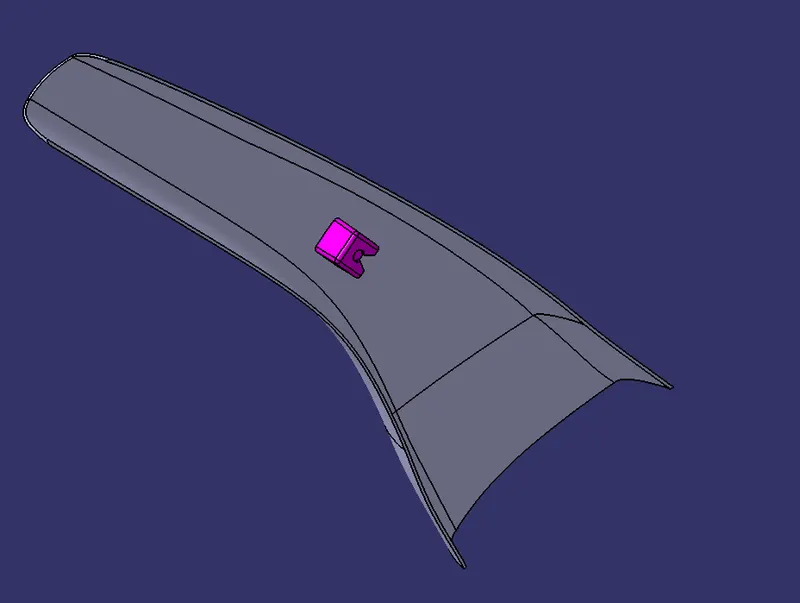
FINAL OUT PUT
TRIM CLASS B With CLASS (A+C) surface
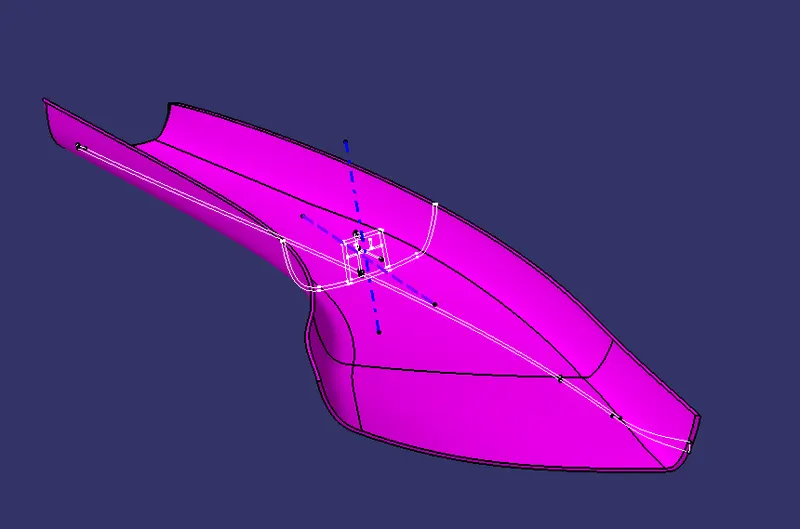
Then go to part design insert a body and use Closed Body command
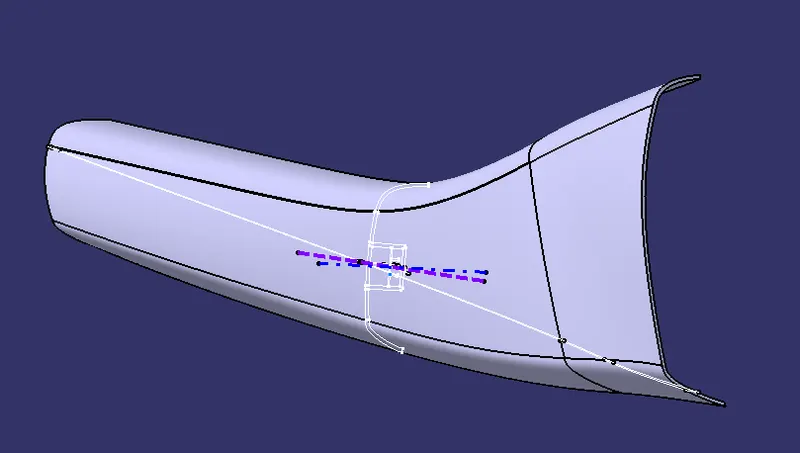
Thus SOLID PART IS CREATED.
B SIDE FEATURES:
B side features are Engineering features which is used for fixitation , guiding or mating to other components
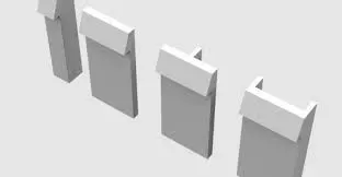
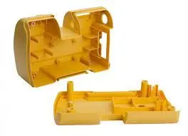
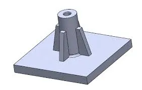
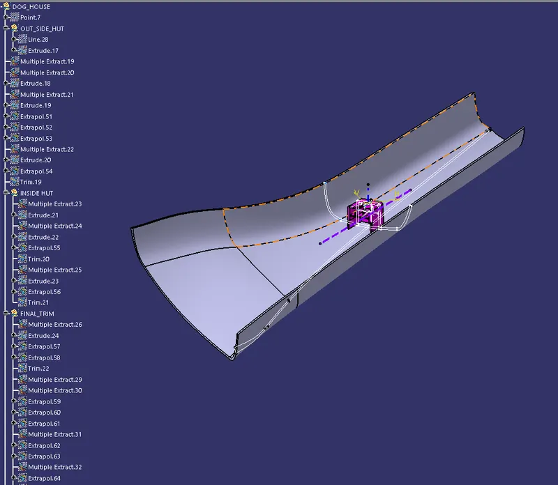
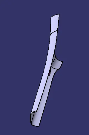
DOG HOUSE CREATION:
Add an Axis system to the point in DOG HOUSE Master section
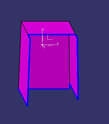
Extract the lines which is the outside faces of the Dog house and then Extrude it
finally TRIM all the unwanted surface
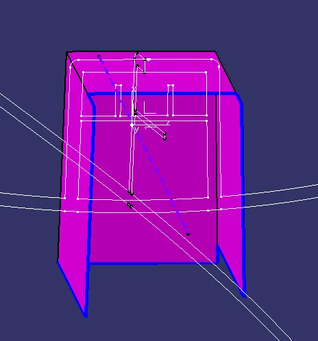
Create the inner face using the inside lines
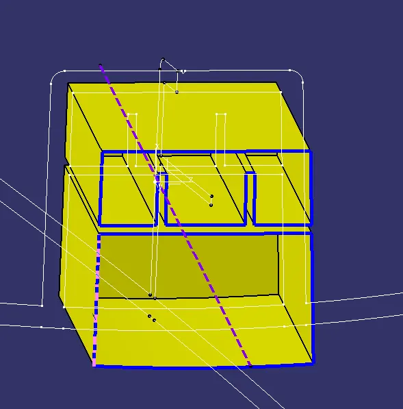
FINAL DOG HOUSE TRIM
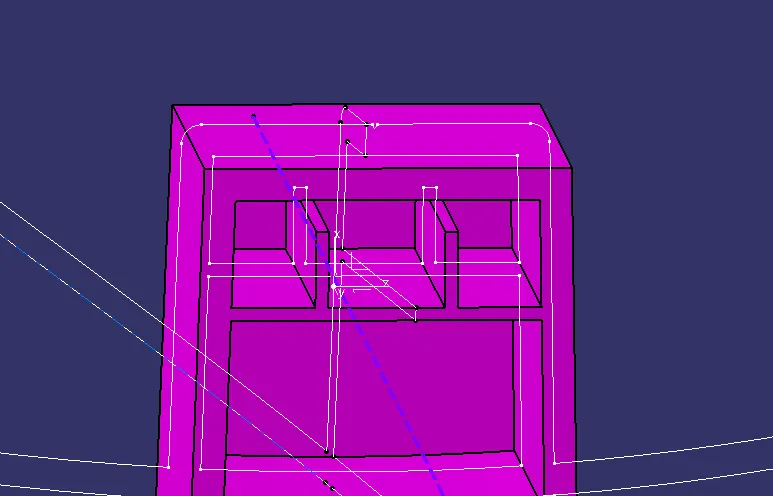
Give FILLETS by measuring the master section
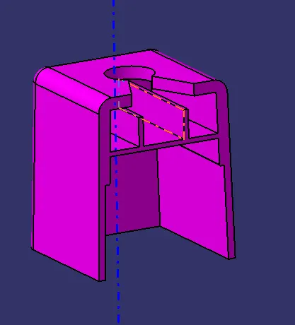
USE SPLIT COMMANT TO GET THIS PERTICULAR SURFACE
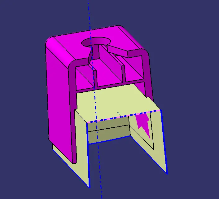
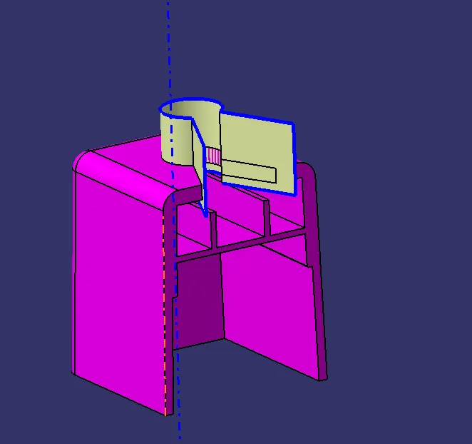
GIVE DRAFT ANGLE of 0.5 Degree to component ejection
FINAL OUTPUT :
DRAFT ANAYSIS
MAIN TOOLING AXIS :
SIDE CORE DRAFT ANALYSIS :
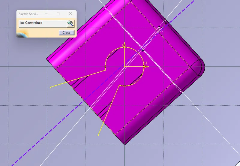
SKETCH ISO CONSTRAINT
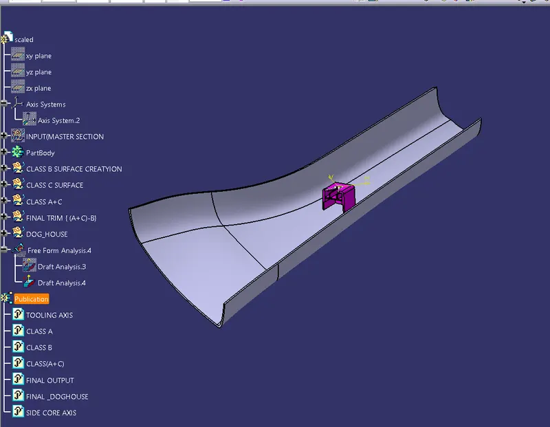
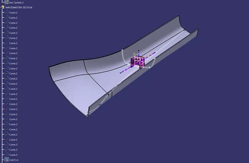
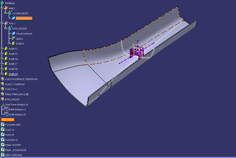
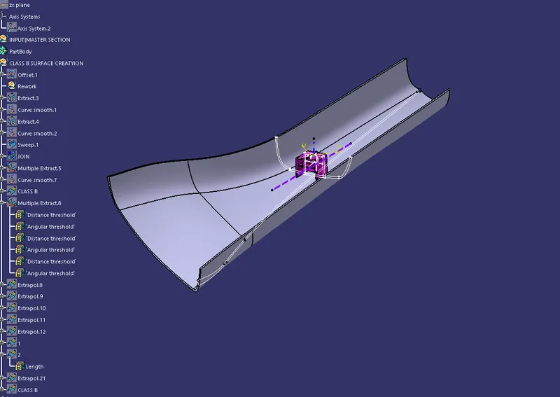
TREE STRUCTURE
ISOMETRIC VIEW
FRONT VIEW
TOP VIEW
RIGHT VIEW