Week 11 - Project - A pillar Design with Master Section
To create the A-Pillar's Plastic component from the given Class A Surface using the Master Section that is provided while following all the design rules.
THEORY
CLASS A SURFACE: Class A surface is a surface made by the designer specially in automotive design which is the aesthetic part of a body and is given as an input to the plastic designer to work on it.
CLASS B SURFACE: It is a surface which comes below the class A surface with a particular thickness. This surface contains engineering features of a model.
CLASS C SURFACE: It is the surface which joins class A with class B surface.
MASTER SECTION: Master sections are the guides for design requirements which decide the component packaging after technical (Styling, Concept or Class-A) surfaces. Creating this master section should need 5 to 6 years of experience. This helps you to decide the feasibility, clearance, the packaging and the fixation strategy before working it on a 3D.
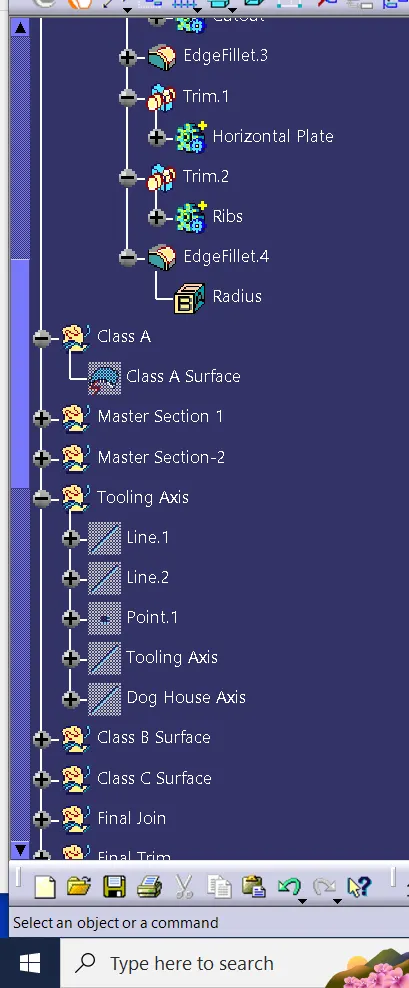
TOOLING AXIS: Tooling axis is the direction in which the core and cavity opens. If we are using proper tooling axis, we can avoid adding side cores thus the cost of manufacturing the component can be reduced.
It is defined as the direction in which the mould/core and cavity open. Selection of the direction of the tooling axis depends on the ease at which components can be easily ejected.
Generally tooling axis is decided from the natural axis of the design, that is, tooling axis is analysed with the x, y and z axis of the system. If the axis doesn’t clear the draft analysis, the next step is to look for the surface in which the drafting axis can be created in such a way that the axis is normal to the surface taken. These are the methods of deciding tooling axis. Bisecting method is the least used method.
BISECTING METHOD: It is a method used to create tooling axis. The sides of the surfaces are chosen in such a way that the edges may affect the tooling axis are taken as the input for the creation of tooling axis. This axis is then created by giving the line type as bisecting line and the inputs as the lines constructed from the edges that affects the tooling axis. This is not frequently used technique for creating tooling axis.
Here, tooling axis is created using the reference from the master section. As there is a doghouse present in the B side, the sides of the doghouse is taken to created the tooling axis. Two lines are drawn from the edges of doghouse and another line is drawn by using the line option as bisecting line, with inputs as these lines. Thus, the line obtained after these inputs is the tooling axis obtained from bisecting method.
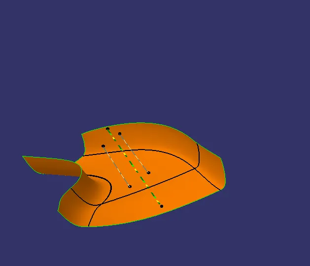
DRAFT ANALYSIS ON THE CLASS A SURFACE:
Next, We will perform a Draft Analysis on the Class A Surface itself:
Before starting with a Draft Analysis Operation, we will go to the 'Customize View Parameters option under the 'View Toolbar'. Then we will enter the 'Customize View Mode' where we will go under the 'Mesh' option and select 'Material' and press 'OK'.
To start the Draft Analysis in the 'Generative Surface Design Workbench, we will go to Insert and then look for the option called 'Analysis'. Once found, we will go under that and click on Feature Draft Analysis. This will open the Draft Analysis Dialogue box. There, we will ensure that under Mode we have selected Quick Analysis under Display we will select Show or Hide the Color Scale and then select 3 Degrees as the permissible draft angle. Then, under Direction we will choose the icon with the symbol of the compass on it which stands for 'Use the Compass to define the new current draft direction.
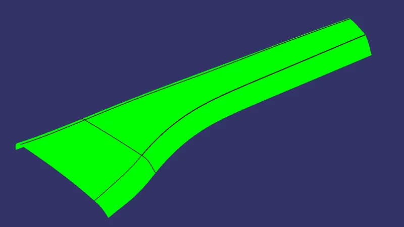
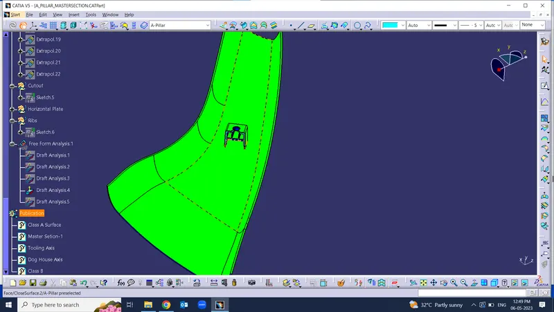
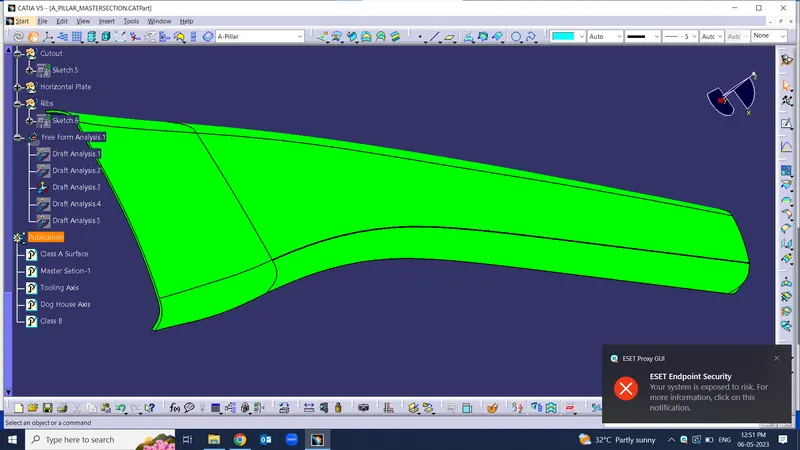
Surface will be in green if the draft angle is more than 3 degrees, blue if draft angle is between 0 to 3 degree and red if draft angle is less than zero degree.
Three degree is the nominal value for draft, whereas 0.5 degree can also be manufactured at ribs.
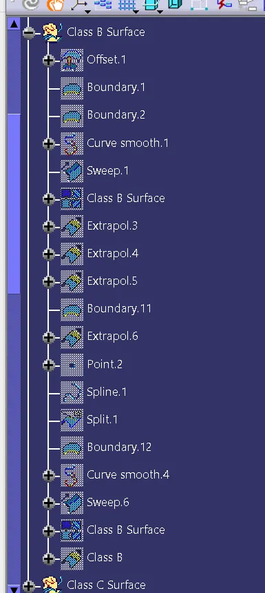
Creation Of Class B Surface
- Now, Class B surface has to be created. For this surface should be offsetted for 2.5mm.
- Publish class B surface.
Creation Of Class C Surface
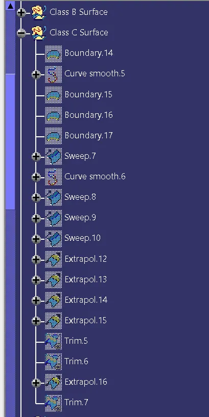
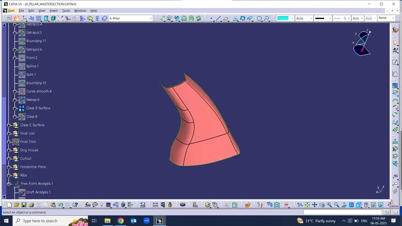
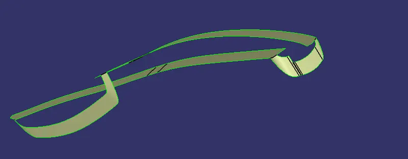
- Now class C surface has to be created and it is created from the boundaries obtained from the Class A surface. This boundary is provided as the input curve for sweep command. Using sweep command, class C surface is created.
- Appropriate sweep is the provided considering the flash and considering manufacturing procedures. Surfaces are extrapolated if necessary.
- Publish class C surface.
Creation Of Closed Surface
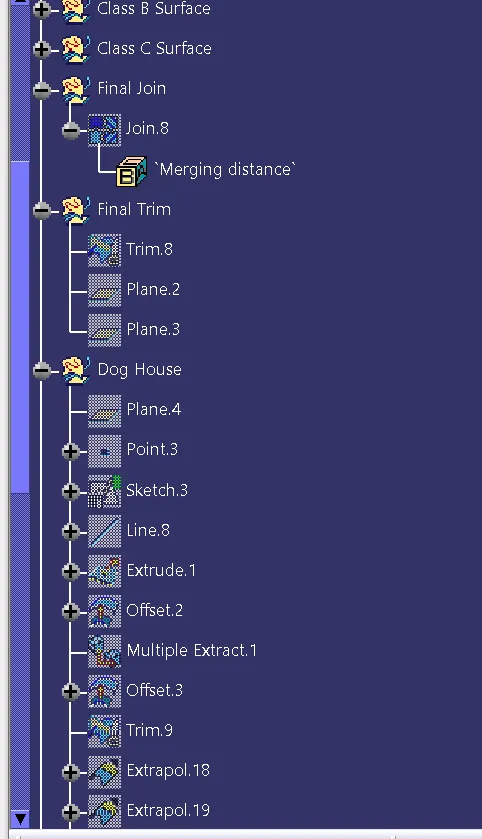
- Now Class A c with B surafceis joined.
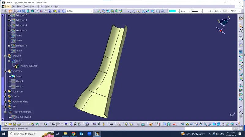
Creation Of Doghouse
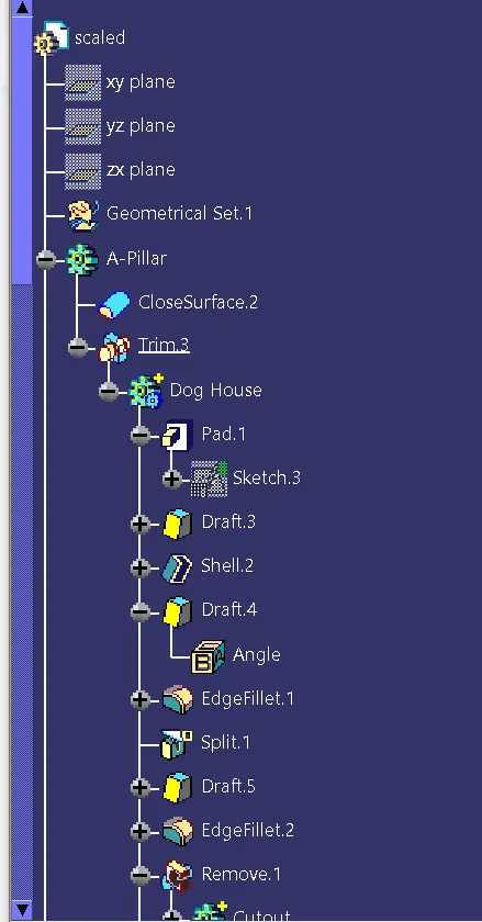
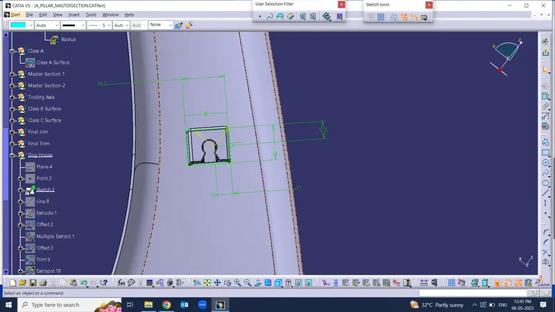
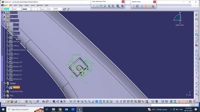
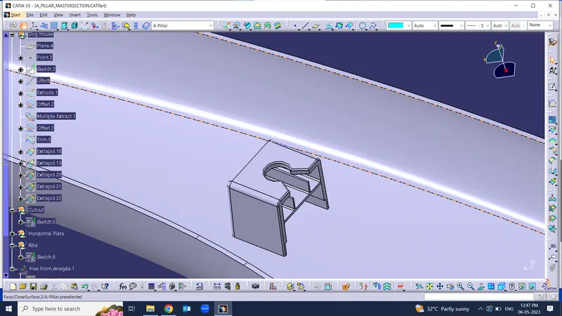
- Doghouse are created by following the design rules.
- For this, sketch is created from the master section provided.
- It is then made to closed body and is made to part model.
- Shell operation is performed to get hollow structure and then coring is done in order to avoid sink marks in the class A surface.
- Drafts are given for the surfaces as per design rules and proper fillets are also provided.
- As per the given master section, ribs and supporting features are also added in the doghouse.
- Then, the doghouse is added to the main body.
All the sketches used are iso-constraint.
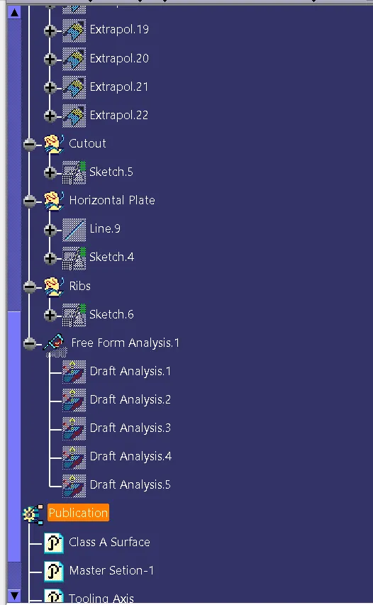
Draft Analysis Of Plastic Component
- The obtained part is draft analysed to check for the correctness of obtained model by following the draft analysis procedure mentioned above.
Side core has to be created for the doghouse to get ejected. So, a side core axis is also created for checking the draft analysis of the component.
Minimum of 0.5-degree draft is provided and the B side engineering features are analysed using the side core axis. Green colour is obtained in the draft analysis, which indicates that the draft provided all are in correct direction.