Week 11 - Project - A pillar Design with Master Section
AIM ; To design A -PILLAR , from the given input mastersection and CLASS A surface.
OBJECTIVE:
The main objective of the project is to create a solid body from the given class A surface and the master sections, and performs draft analysis in the various stage of design.
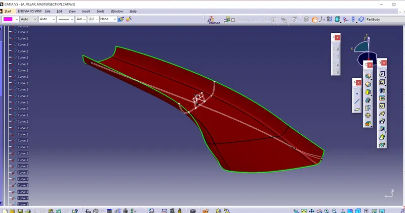
GIVEN CLASS A SURFACE:
TOOLING AXIS CREATION:
For this part tooling axis creation is done by using the mater section which is given along the Class A surface. Because in this master section the Dog house is there and the Draft for the wall of the Dog is given by the tooling axis. So can take tooling axis from the master section. This master section and Class A surface is given below.
Create the point using between 2 points as shown below
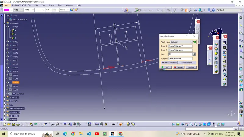
project the points on edges of mastersection , so that we can draw the lines on edges of master section, now points have connection with mastersection , to remove that connection we have to ISOLATE the points. the draw the lines using that points. as shown below:
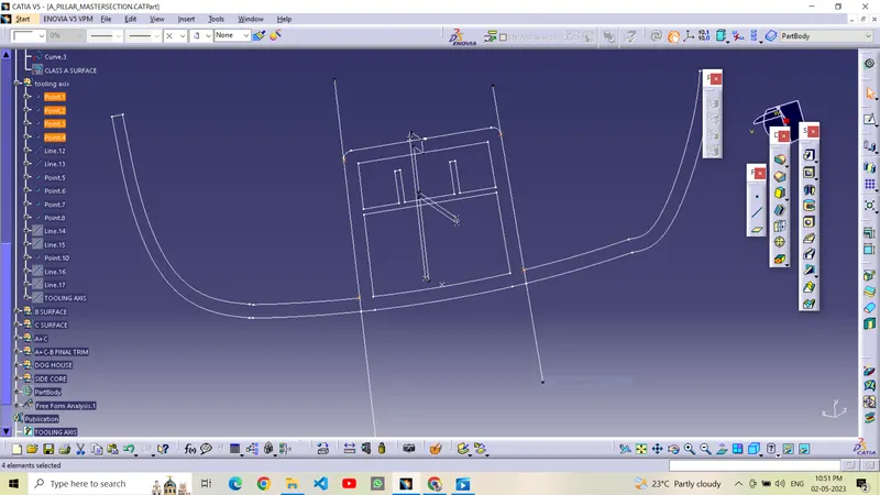
by using that lines we have to create the TOOLING AXIS by BISECTING THOSE LINES
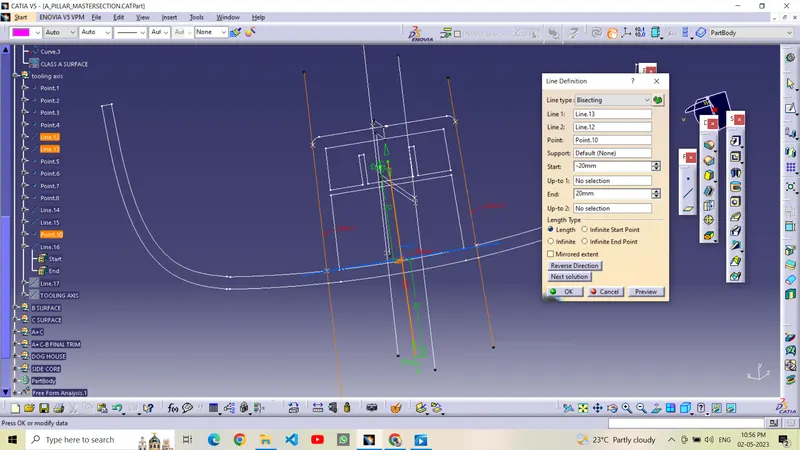
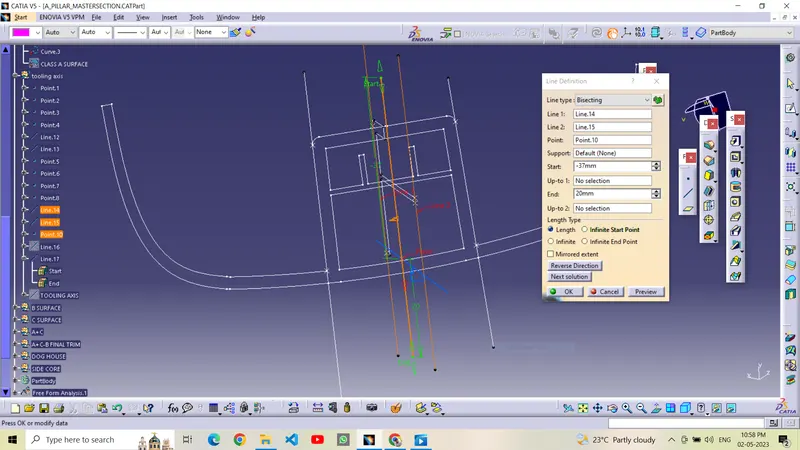
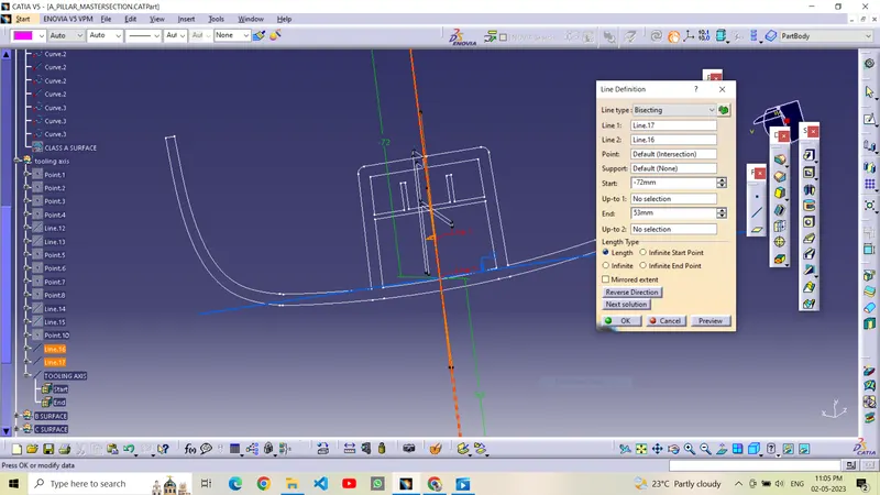
resulting tooling axis as shoen below;
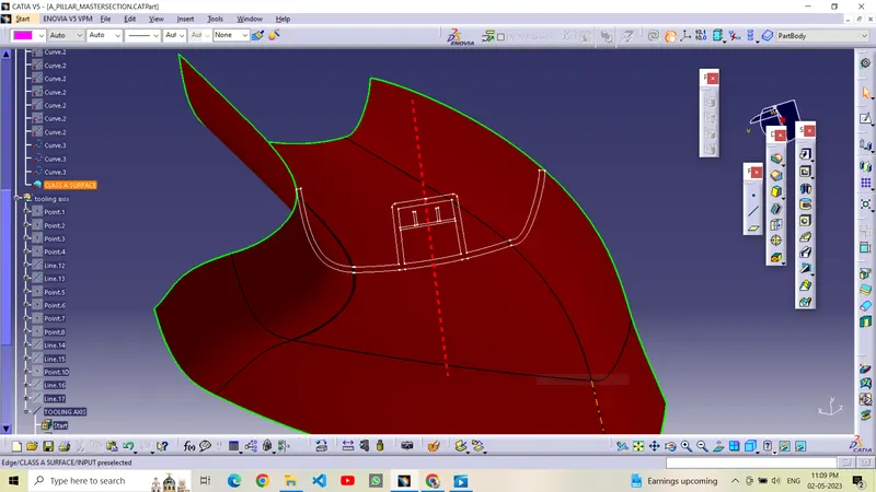
DRAFT ANALYSIS ON CLASS A SURFACE
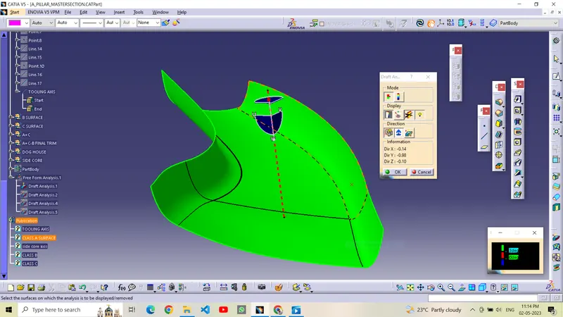
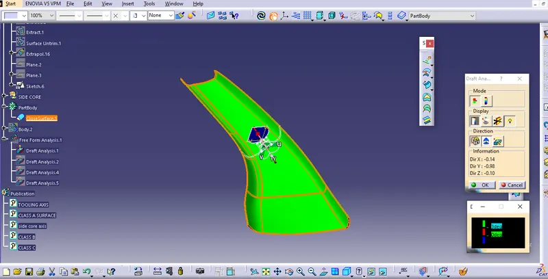
The draft analysis check is performed on the surface is to check wheather it satisfies the min draft angle as per the standards, the draft analysis on class A surface is doing before the creation of solid is to check whether the class A is drafted properly or not..The draft analysis is first done on the given class a surface with respect to the tooling axis , in that analysis the class A surface is cleared the min draft angle of 3 deg as shown in the fig.
Class B surface creation:
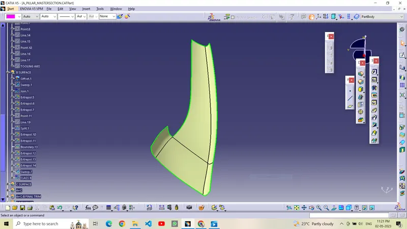
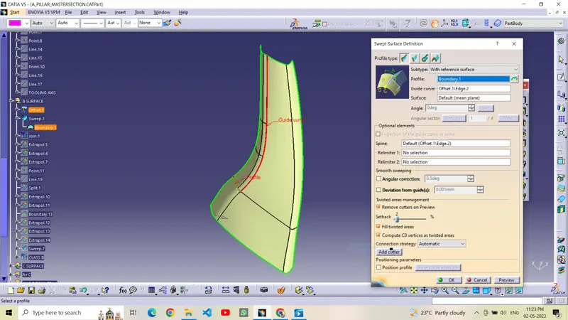
To create the class B surface initially, I measured the thickness of the master section (2.5mm). I offset the class A surface 2.5mm to the inside direction. The styling fillets on the class A surface are not offset properly, it created the patch on the offset surface. I used the sweep command to close the patch on the offset surface.
Class C surface creation:
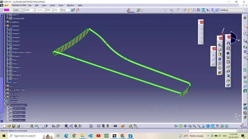
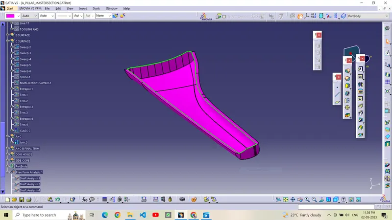
To order to create the class C surface, I used the sweep command. I sweep the class A surface edges along with referencing the surface inside with 90deg. After the creation of the class C surface, the surface edges are needed to be extrapolated to intersect properly from all 4 sides. I trim the surfaces which extrapolated, to get the closed class C surface. I joined the class A surface and Class C surface to get a single surface of class A+C surfaces. I trim the Class B surface with class A+C surface join, to get the closed surface to create the solid body.
class C surface:
class A+C join:
Solid part body creation:
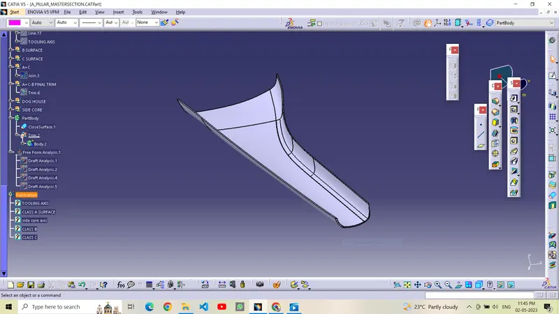
To create the solid part body, I used closed surface command in the part-workbench. I gave the closed surface as an input in the closed surface command.
Dog House creation:
- To create the dog house on the B-side, I extracted the lines on the master section and I create a plane to extract the lines concerning the master section.
- using that lines pad it to required length measuring master section.
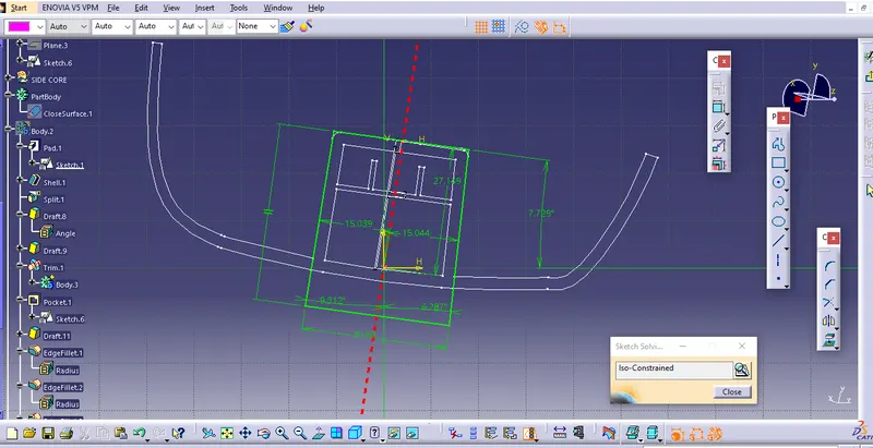
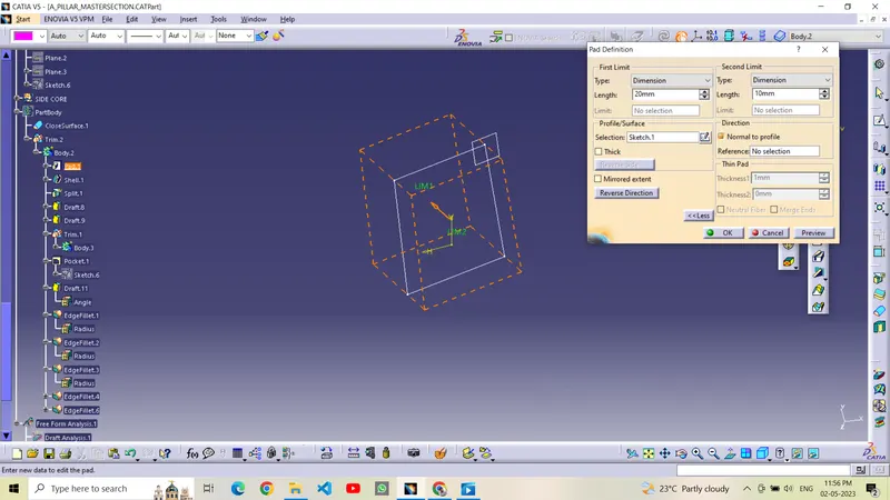
shell it to required thickness, REMOVE THE UNREQUIRED SURFACES and draft the inner(0.5 degree) and outter faces as per design rules
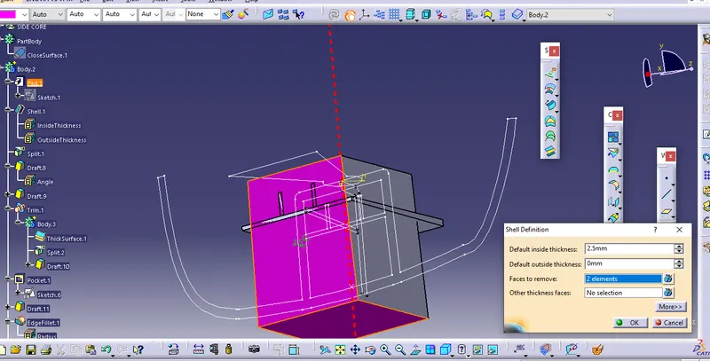
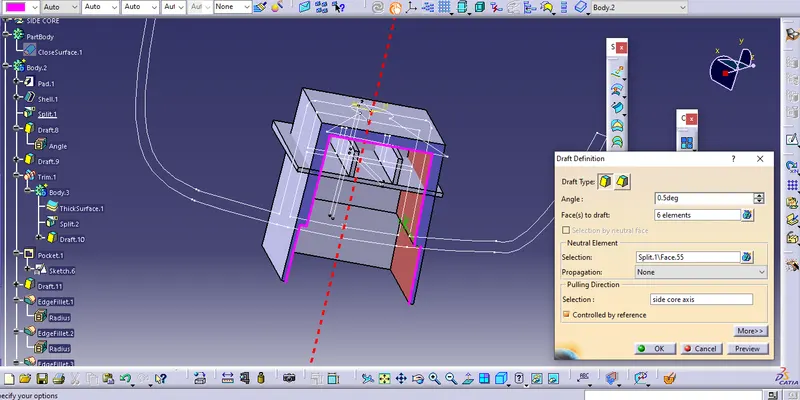
design the DOG house as per design rules and give the edge fillets and do the RIBS AND cutouts as given
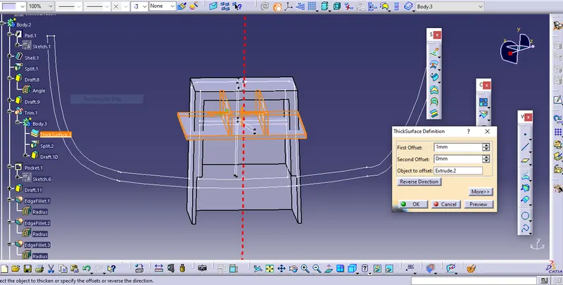
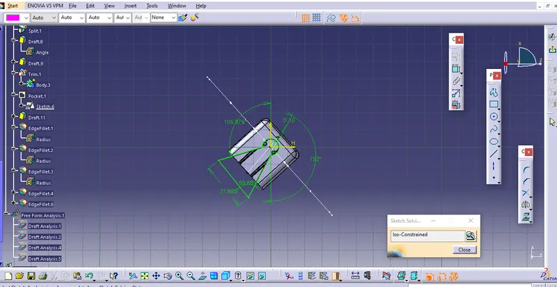
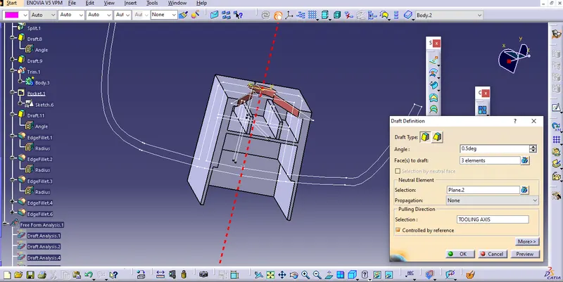
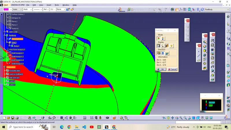
do the draft analysis for DOG house.Draft analysis is performed with 0.49 deg min draft angle for the inside area of dog house with respect to side core tooling axis as shown below, 0.49 is used because there may be the chance for minimal deviation of draft angle.
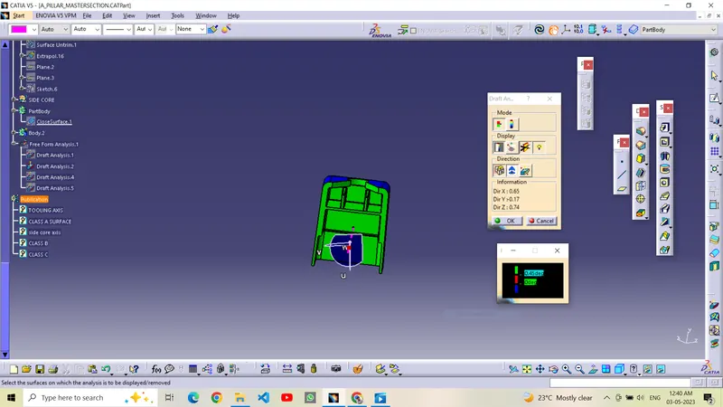
now do union trim with this close surface.and do the draft analysis, using tooling axis and side core axis.
using main tooling axis:
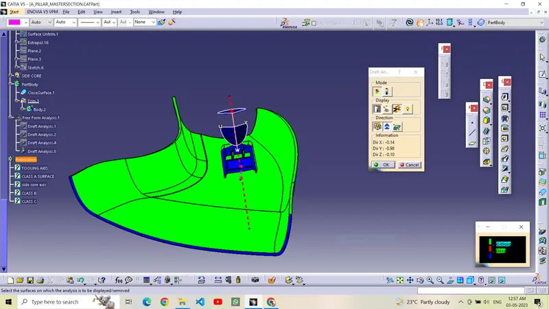
using side core axis for dog house: