Week 8 - Challenge 3 - Coin Holder Design
GIVEN CLASS A SURFACE:
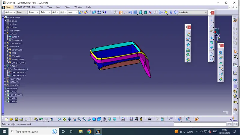
TO Find the tooling axis of the component:
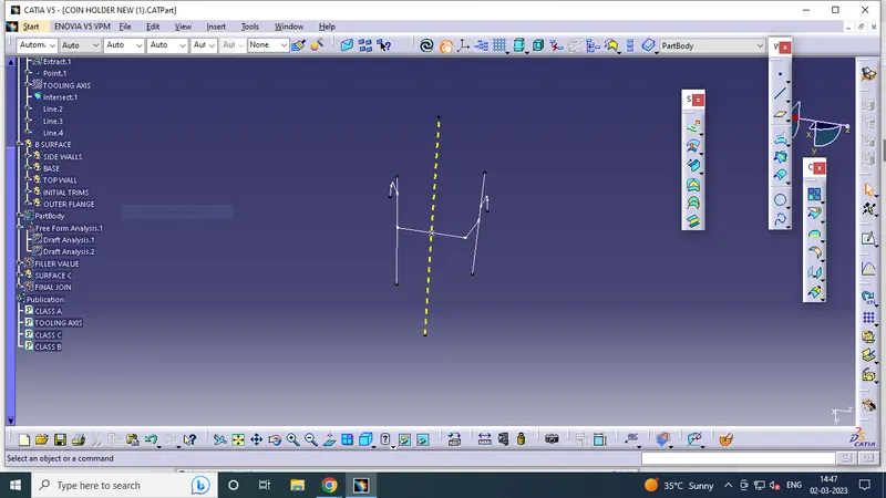
Check the connectivity of the surface and ensure there will be no gap between the surfaces and then define the tooling axis.While creating a tooling axis please ensure to give the tooling axis on a flat length surface or the surface which have a hole on it.Create a point on the middle of the base surface by using point on the surface command then create a intersection for the surface and extract the reference lines which will be helpful for creating the dummy tooling axis using the intersect method by creating a bisecting line.
AS walls are perpendicular to surface to the where the tooling axis to be made ,by checking wall angle against sutface where tooling axis will situvated itself we can do the tooling axis, both will result in same as done in model below
DRAFT ANALYSIS:
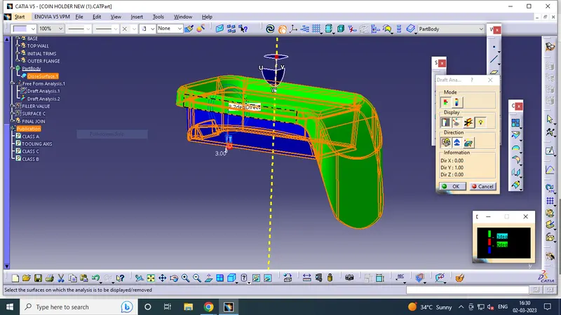
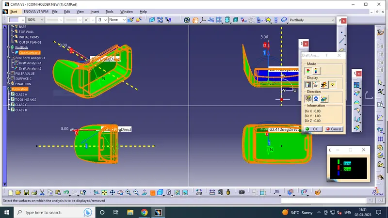
Now perform the Draft analysis using the Featured Draft Analysis tool in the tools.Once the draft analysis toolbar is opened, go to the display block and select the 'Analysis under the running point' command to check the angle for different sides on the class A surface. The color scale on the bottom visualizes, whether the draft angle meets the requirements or not (3 deg) by indicating the colors Green, Blue and Red. Once the draft angle analysis was done, we need to align and fix the compass to the tooling axis of the class A surface
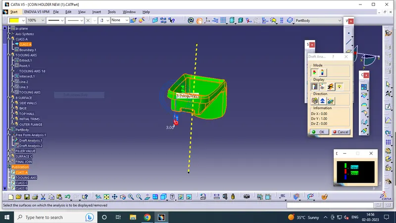
above image is Draft analysis of Class A surface.
Now creating Class B Surface:
Extracting the wall surfaces using extract option from Class A surface.Then perform Extrapolate inorder to increase the length,Now trim the surfaces to required surfaces.Then Offset the surface inorder to get the required thickness.
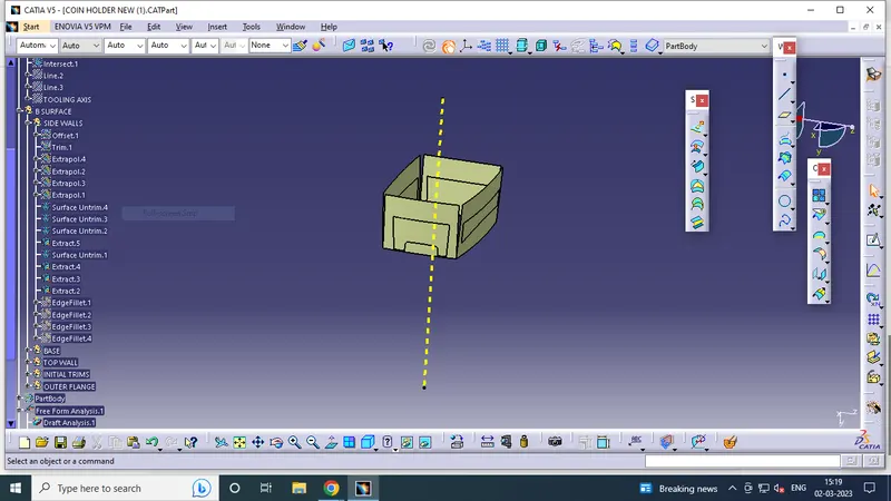
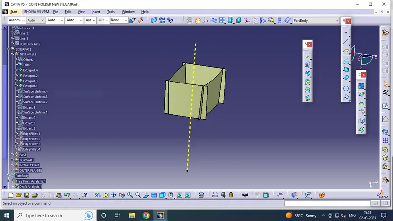
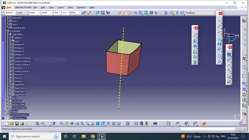
Base surface of the component is then extract, untrimmed, extrapolated, offset and trimmed.
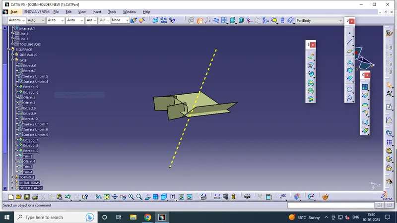
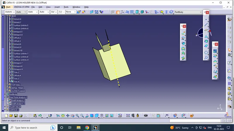
now exratct the top surface ,extrapolate and offset to req thickness
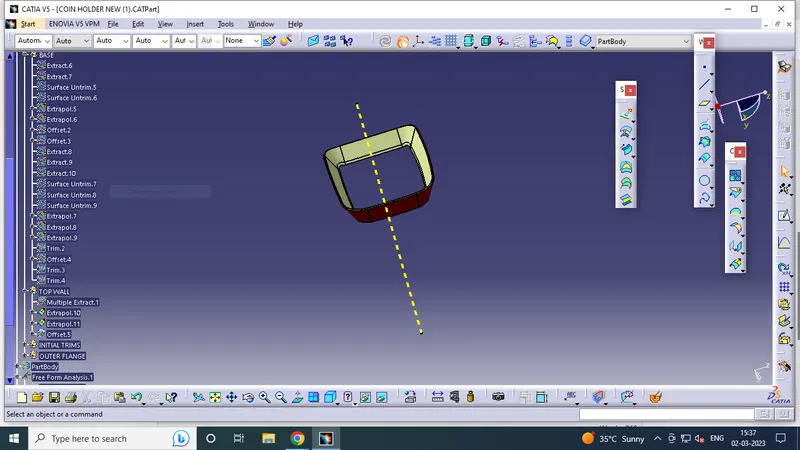
now trim the all surfaces
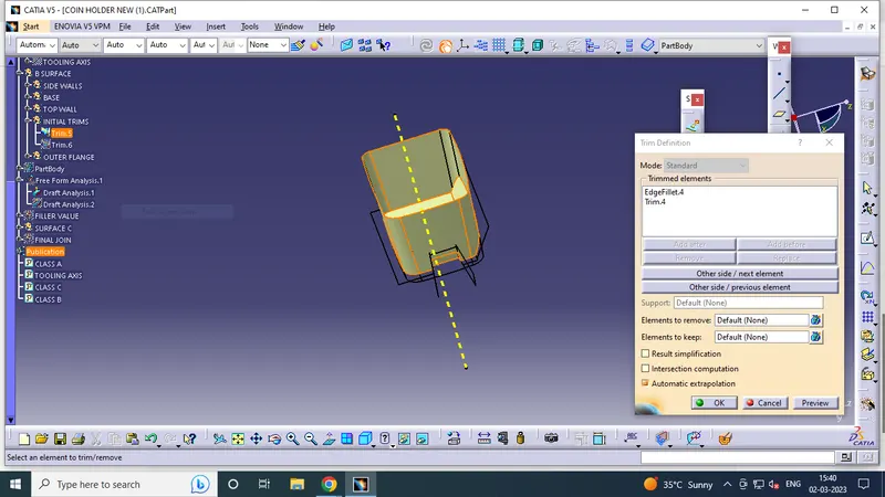
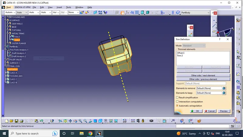
now extract the outer flange
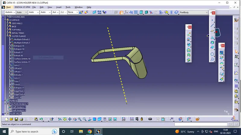
extrapol the flange surfaces
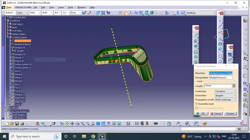
extrapole and untrim the below surface and join the both surfaces
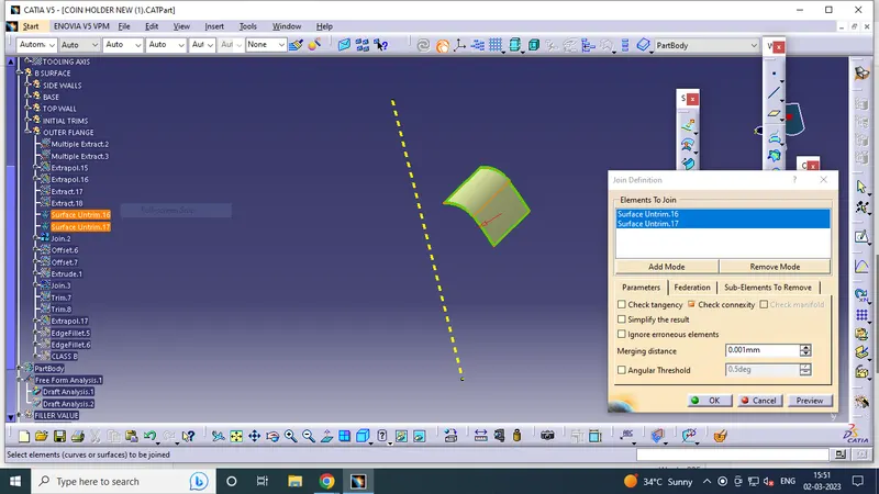
offset the outer flange surafaces to req thickness ie,2.5mm
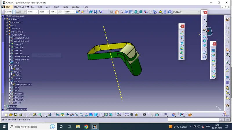
now trim all surfaces together and give the fillets as req by measuring class A
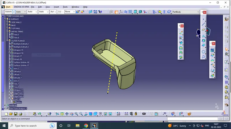
Now creating Class C Surface:
C surface has been created from the boundary lines of class A surface and by extracting the supporting surfaces then sweep the boundary lines with reference to the extracted surfaces.Create a sweep with reference to the curve and the reference surface with a 90 degree angle and give the inside direction Check for the continuity of the surfaces if there is any gap go for extrapolated and trim all together now we will get the class C surface.
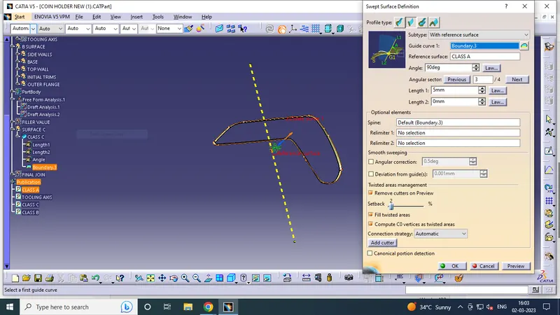
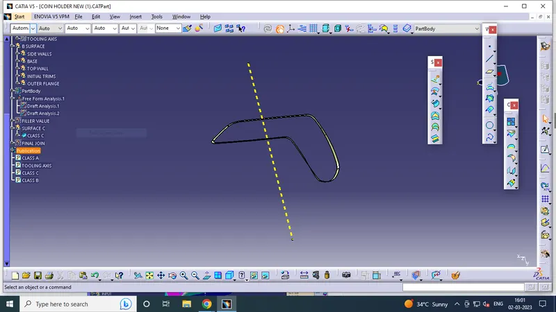
now join the class A and Class C surfaces
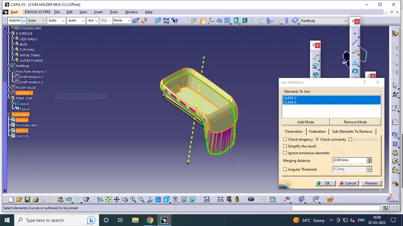
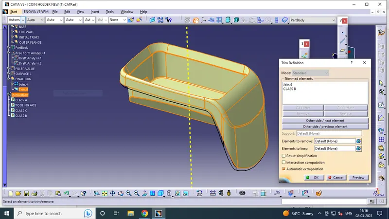
trim the above result with class B to get the req component
Closed Surface:We then swutch to part design to create a final platic component using closed surface option.
final part component:
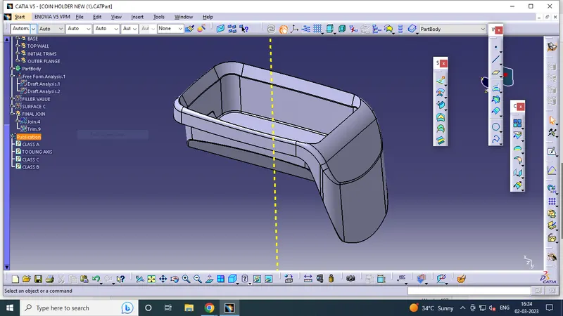
Draft analysis report for final plastic component: