Week 8 - Challenge 2 - Switch Bezel Design
Report:
draft analysis and the tooling axis creation, creating the tooling axis, & the Bisecting method.
GIVEN CLASS A SURFACE:
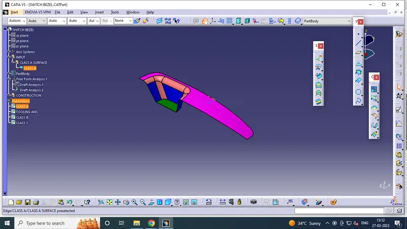
TO Find the tooling axis of the component:
- At first we identify the proper location for the tooling axis to pass through. In this model we find the base of the switch besel to be the ideal surface for tooling axis.
- So using 'multiple extract' we first extract this surface.
- Then we create a point on centre of this surface using point option.
- With this point we create an axis system.
- Looking at the model we identify that tooling can be done through both y and z axis.
- So we first take the yz plane as the reference and using sketch we create a dummy tooling line with respect to the two side walls
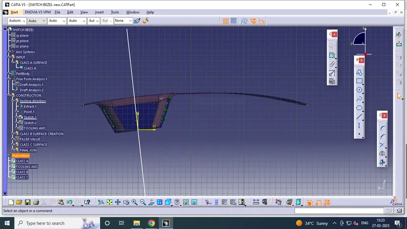
- Then using the zx plane we create another dummy tooling axis.
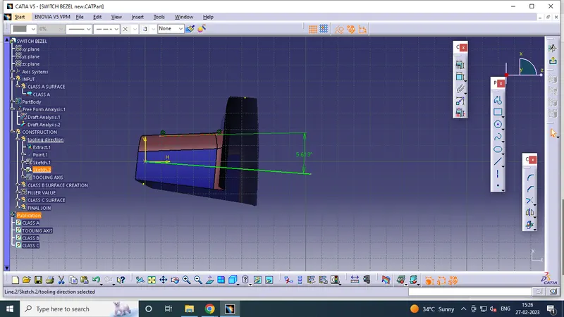
Create a bisecting line for the inclination lines as shown below:
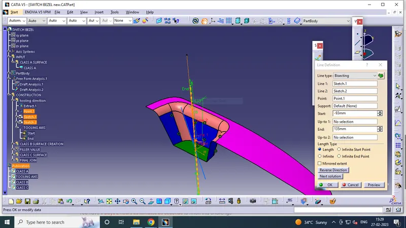
now by bisecting slanted lines we will get the main TOOLING AXIS as shown:
Bisecting method is basically use to find the proper tooling axis using the dummy tooling axis. In Bisecting method, bisecting line is used which either bisect the two line , if it will show error which means the two lines are parallel to each other. In order to know whether the particular surface is toolable or not we intersect the surface with the respective plane and get a sketch which consist of two lines and with the help of bisecting line option we bisect the line which creates a line at the mid point of the two lines. Like wise we create tooling clearing axis for x and y which will be used to create the main tooling axis using the bisecting line option in in the line comand.
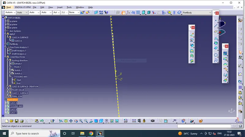
DRAFT ANALYSIS:
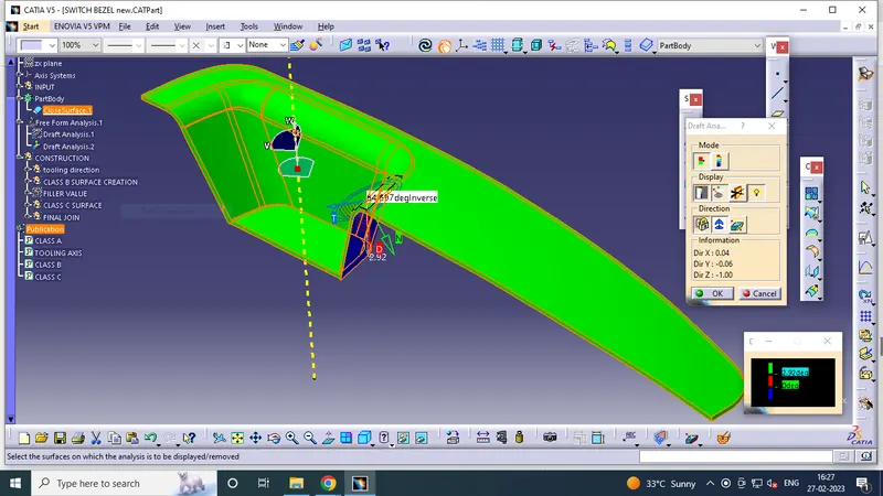
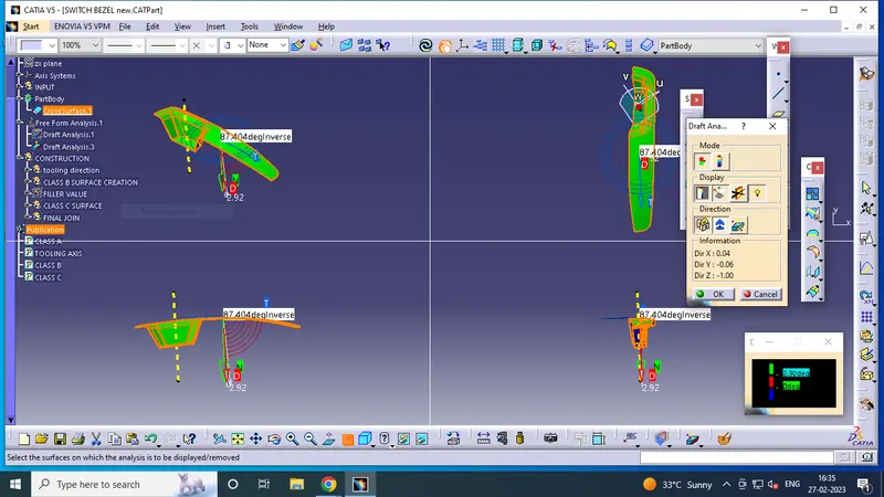
Now perform the Draft analysis using the Featured Draft Analysis tool in the tools.Once the draft analysis toolbar is opened, go to the display block and select the 'Analysis under the running point' command to check the angle for different sides on the class A surface. The color scale on the bottom visualizes, whether the draft angle meets the requirements or not (3 deg) by indicating the colors Green, Blue and Red. Once the draft angle analysis was done, we need to align and fix the compass to the tooling axis of the class A surface
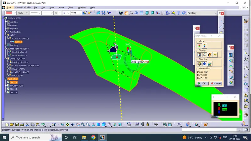
above image is Draft analysis of Class A surface.
Now creating Class B Surface:
Extracting the wall & bazel rest surfaces using extract option from Class A surface.Then perform Extrapolate inorder to increase the length,Now trim the surfaces to required surfaces.Then Offset the surface inorder to get the required thickness.
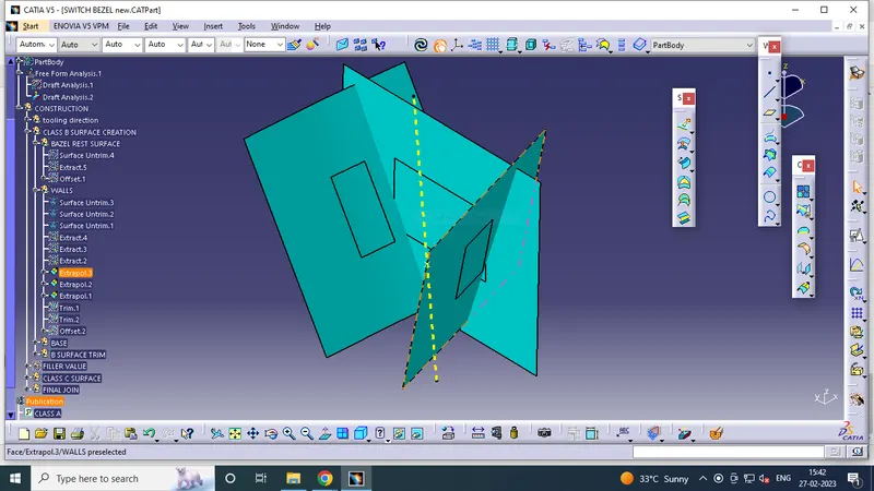
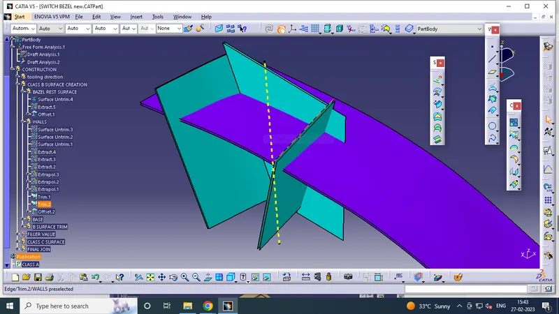
Similary create the above features to base surface also.
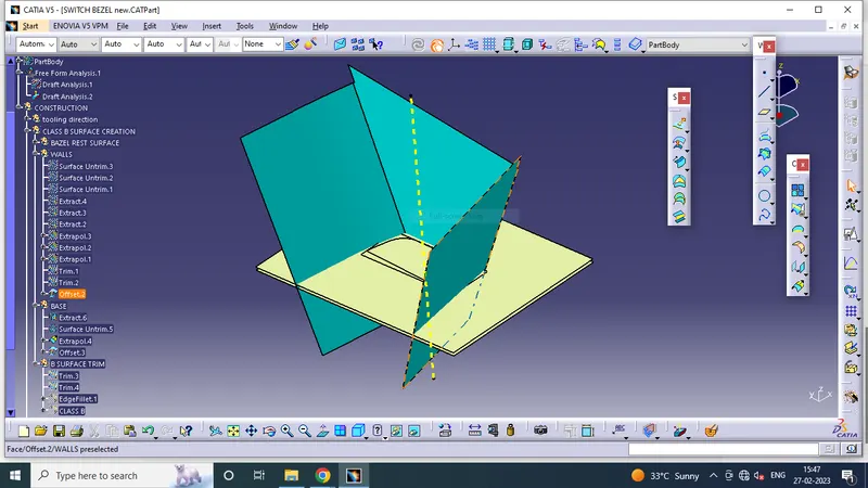
now trim the all surfaces ie, base,wall & bazel rest surface.
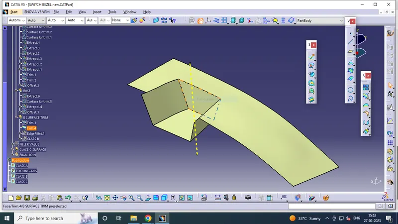
keeping thickness of componet in mind ,now fillet the edges to get the required thikness.
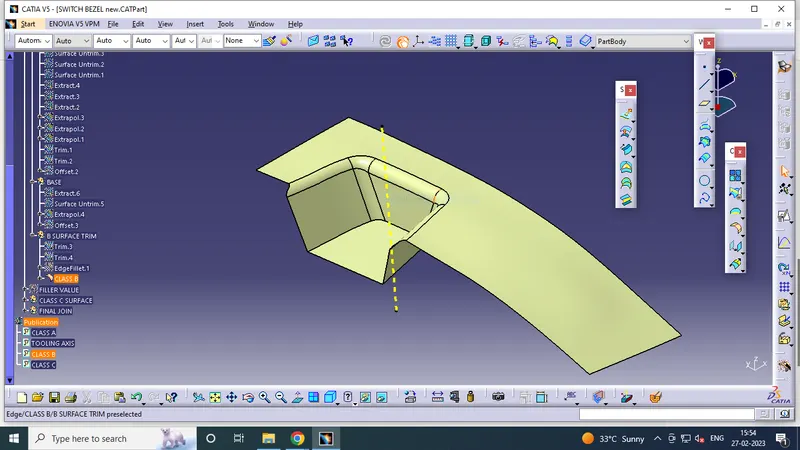
Now creating Class C Surface:
To create a class C surface, I used the sweep command by considering the outer boundary of the class A surface. In the sweep command, go to the 'line' command in the 'profile' block and the subtype is 'with draft direction'. Now select the outer boundary and tooling axis, give 3 deg in the angle (the draft angle for a plastic component is 0.5 to 3 deg) and select the direction to sweep, in this condition the class B surface is under the class A surface so select the inside down arrow to sweep.
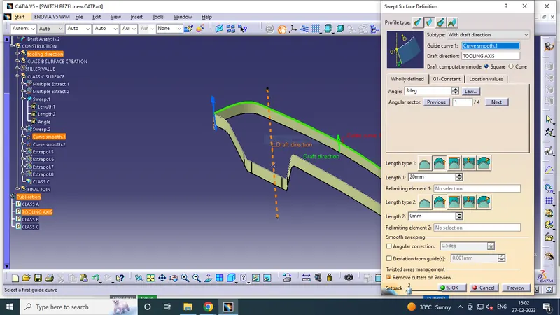
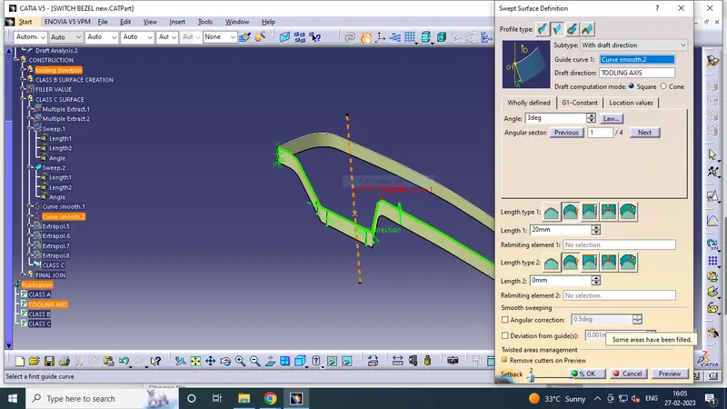
now join the CLASS A and Class C & trim the component with CLASS B surface to get the Required Component.
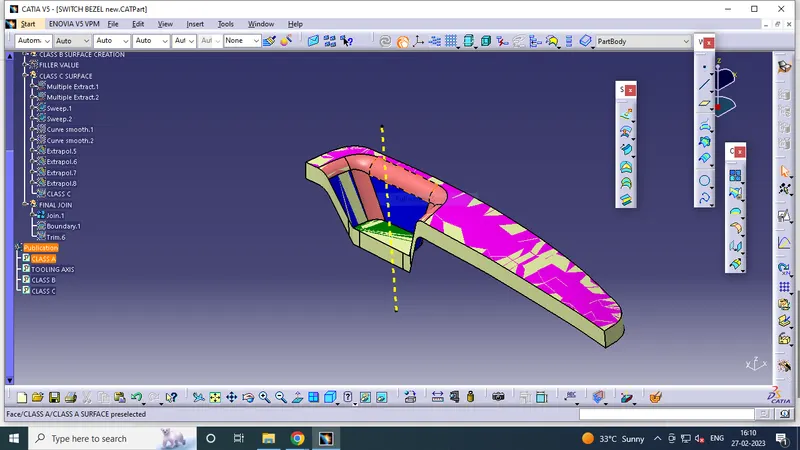
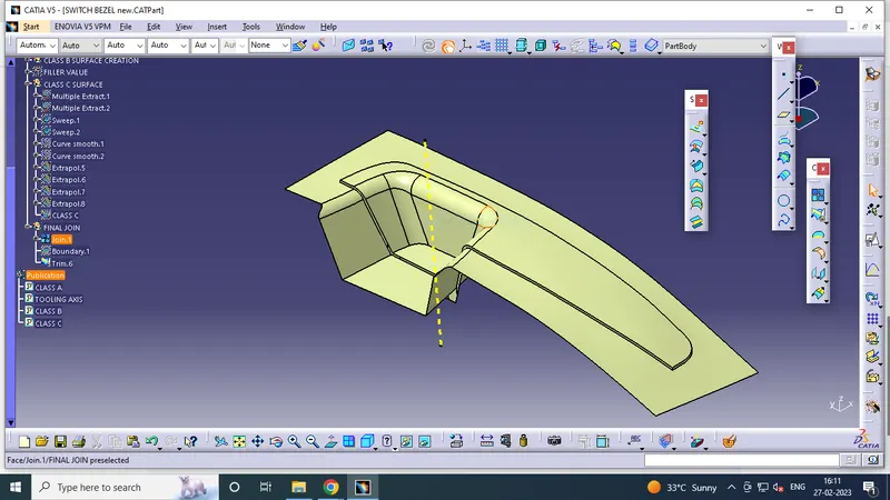
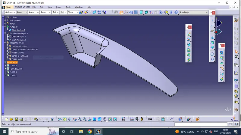
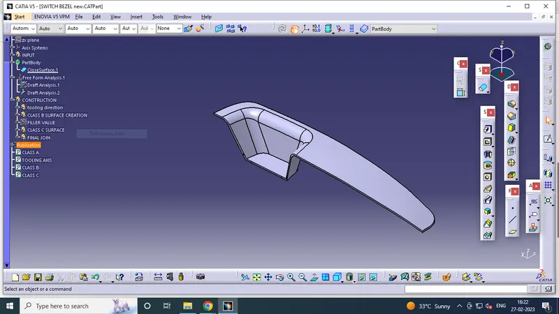
final product as shown below:
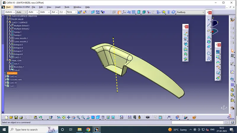
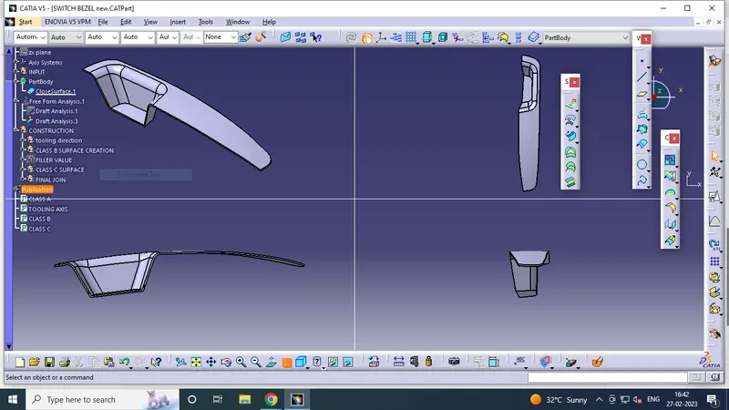
Closed Surface:We then swutch to part design to create a final platic component using closed surface option.
Draft analysis report for final plastic component: