Week 11 - Project - A pillar Design with Master Section
Tooling axis:
A tooling axis/ tooling direction is the direction in which core side and the cavity side of the mould are pulled apart from each other. Generally, tooling direction is decided by the geometry of the component design. Deciding the tooling axis so as to create maximum portion of the part is essential for the manufacturer of the mould as it will affect the cost of the manufacturing process and the product directly. In the given class-A surface there is a dip in the component which can be solved through a single tooling direction, hence while creating the tooling axis a direction perpendicular to this dip is considered.
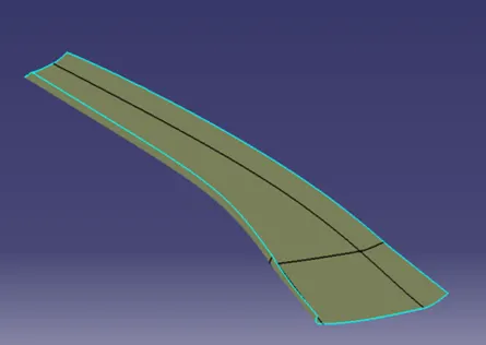
(Class-A Surface)
Creation of toolong axis using bisecting line method-
Now, as the direction is confirmed an accurate tooling axis needs to be created. To do so, a method in which a bisecting line is created between the faces which are parallel to the tooling direction is used. This method ensures the exact angle at which a tooling axis should pass through and proper draft angle of the given parallel faces is maintained.
With the help of given master section, two lines are created by using point to pint command in the line tool. Now, with the bi-secting command a bisecting line is created which is also the tooling axis for the product.
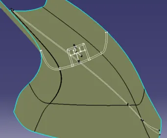
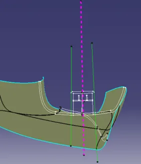
(Master Section) (Main Tooling Axis)
This tooling direction is used to create proper draft angles wherever needed. It is also used for the draft analysis which is presented in the attached ppt.
B-Surface and C-Surface Creation:
Using the given class-A surface and generative shape design workbench the class-B and class-C surfaces are created. The final part is obtained using closed surface command in part workbench.
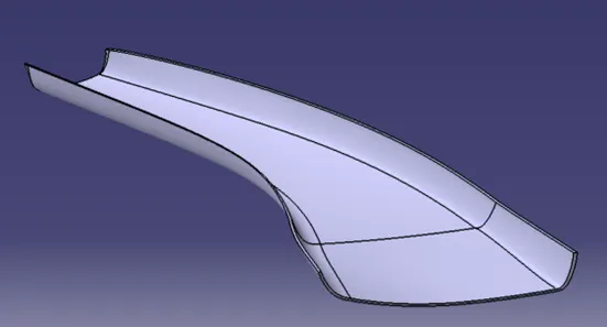
(Closed Surface Part Model)
Doghouse Creation:
Sketches for the Doghouse with sketch solving status bar showing iso-constrained geometry-
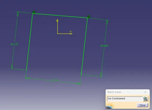
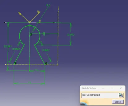
For the doghouse, a side tooling axis also called as lifter axis is needed to create and measure precise drafts on its surfaces-
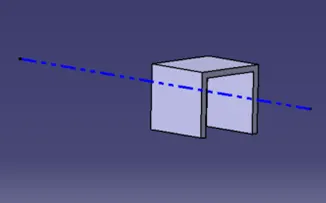
(Lifter Axis)
Final Doghouse Model-
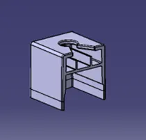
Final Part Model:
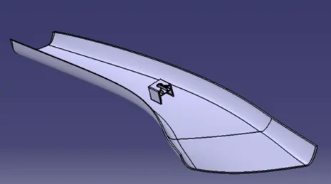
Part Model from different 3-D views:
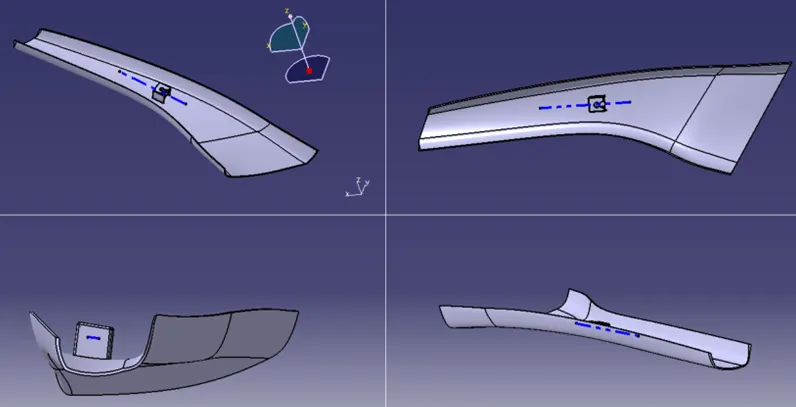
The draft analysis report for both class-A surface and the final part modle is presented in the ppt attached with this file.