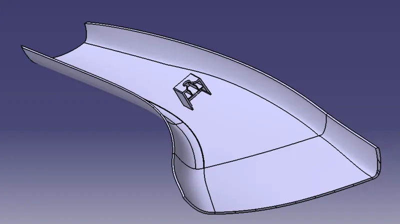
Week 11 - Project - A pillar Design with Master Section
Step 1: The entire Class A surface was analyzed properly for any surface discontinuities and other irregularities.
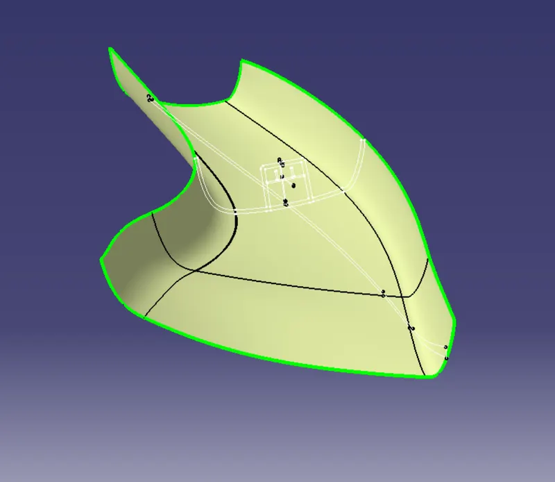
Step 2: Creation of Tooling Axis:
- two master section lines were chosen for the bisection method for creating the tooling axis line.
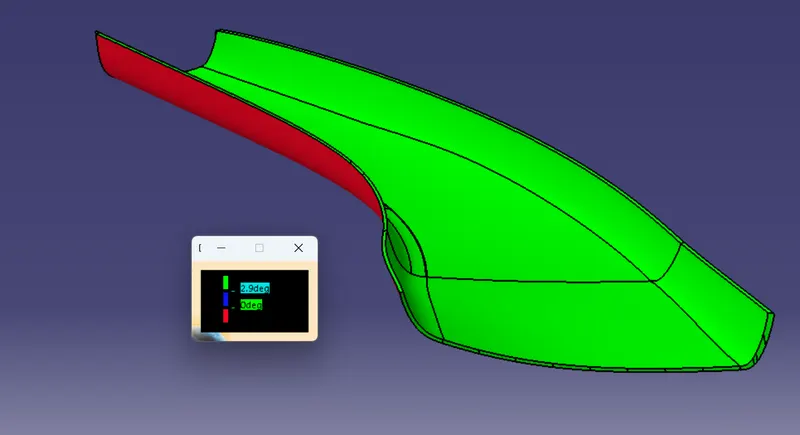
- Now draft analysis was done.
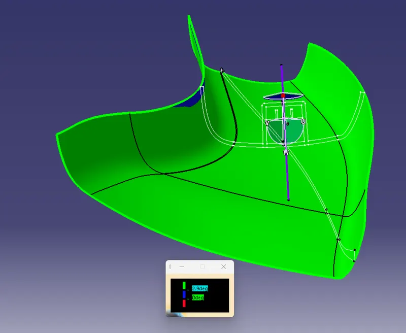
Step 3: Creation of Class B surface.
- An offset of Class A was taken just above it with a value of 2.5 mm.
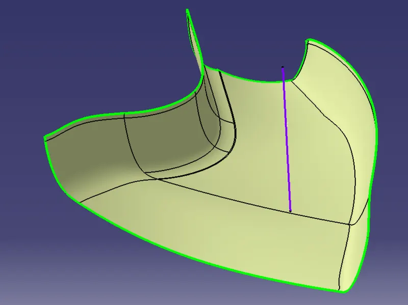
The missing surfaces were made taking offset of those individual surfaces: untrimming them, extrapolating them, and then trimming them together. And finally giving fillet to the edges.
Step 4: Creation of Class C surface.
- The boundary of Class A was swept part by part with a draft of 3 degrees for the bottom boundaries and 90 degrees for the top boundaries.
- Then all of these individual swept were joined together using trim.
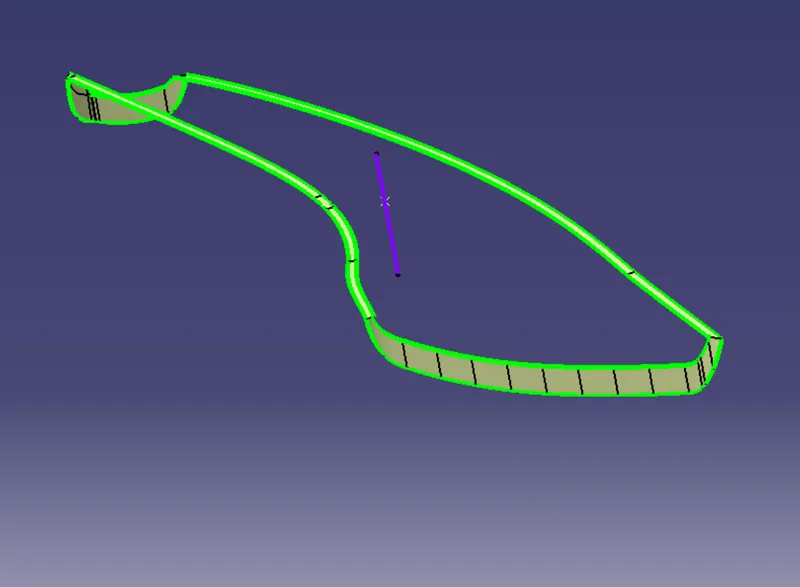
Step 5:Creation of Class A+C
- Class A and Class C surfaces were joined together using the join command.
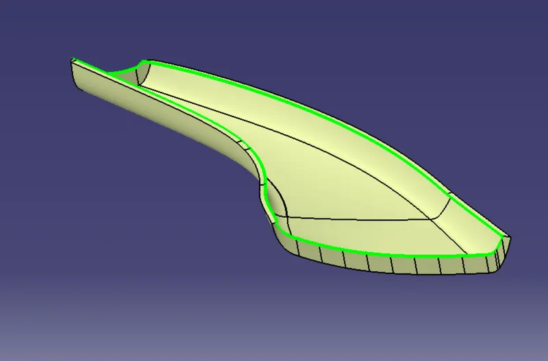
Step 6: Class A+C and Class B were trimmed together.
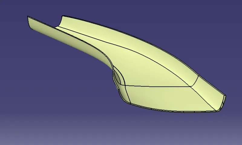
Step 7: Now this final trim was converted to a solid body using the Close Surface command.
Draft analysis:
Dog House:
For the dog house, the given master section was taken as a reference.
- The B surface of the lower substrate was extracted and then a point and a plane was created.
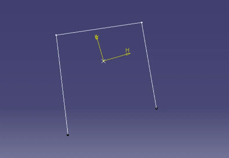
- This sketch was swept up to 50 mm above and 3 mm below with an angle of 1.5 degrees.
- Then the top was closed using the multi-sections surface command and then joined with the swept surface
- Then this was thickened to 2.5 mm
- A line was created on the plane parallel to it and then extruded.
- This was then offset to 5 mm and then trimmed with the main surface, this was then offset to 1 mm toward the solid body.
- This was then trimmed with the main surface and we then get a surface like this.
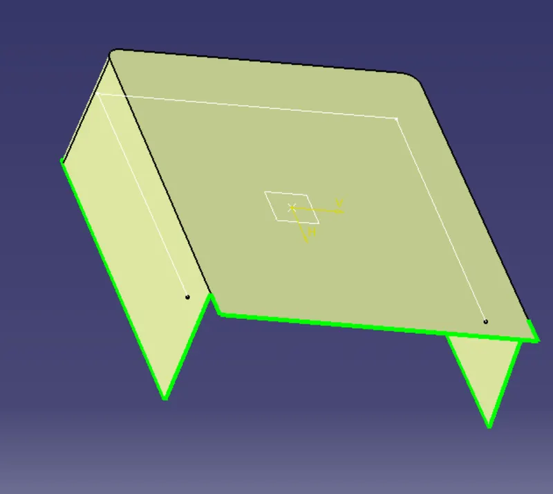
- This was then split with the solid body.
- Then draft of 0.5 degrees was provided to the inner walls with respect to the side core tooling axis.
- And required fillets were also provided.
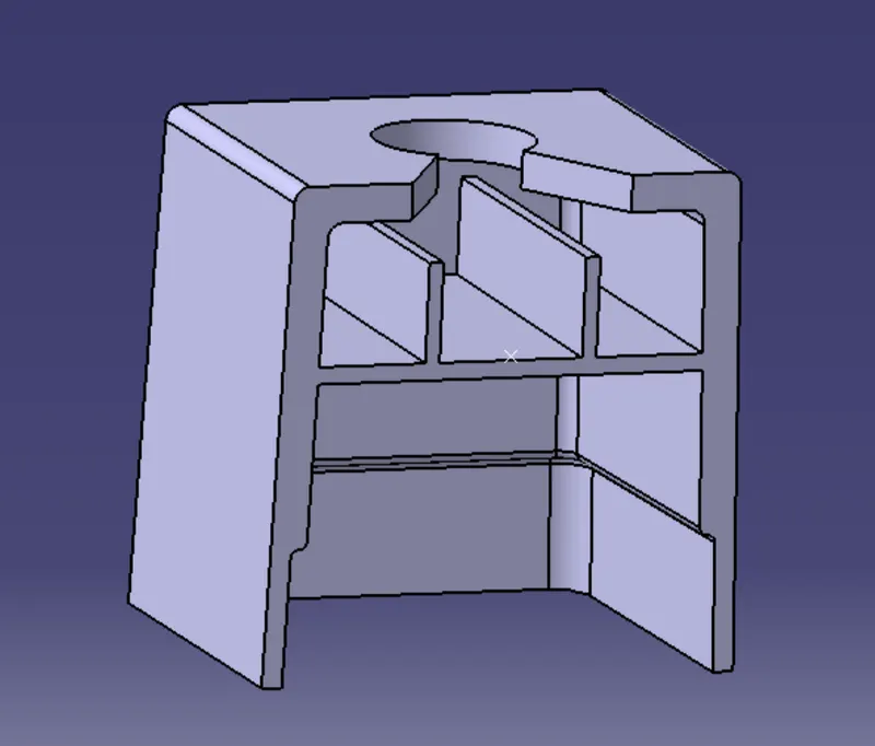
- Then the rest of the features such as the ribs and its base and the top hole were added as per the master section dimensions
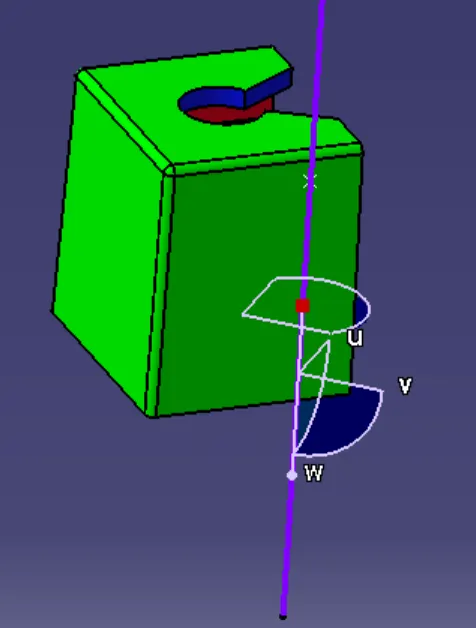
- The outer walls clearing the draft of 1.5 degrees
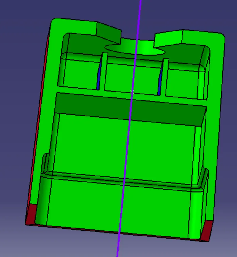
- The outer walls clearing the draft of 0.5 degrees
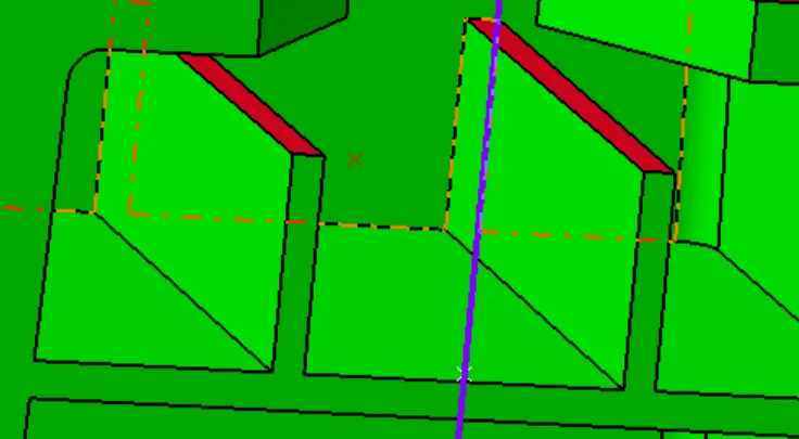
The ribs were clearing the draft of 0.1 degrees with respect to side core tooling axis.
Final part body: