Week 11: Project 2 - Emission characterization on a CAT3410 engine
AIM:
- To simulate the combustion process in a diesel engine using two different piston configurations, omega and open w. It is intended to compare the engine's performance and emission characteristics with these two configurations.
THEORY:
- The diesel engine generates power by burning fuel that is injected or sprayed into the cylinder's compressed, hot air charge. The air must be heated to a temperature above that at which the injected fuel can ignite. Fuel sprayed into air that is hotter than the fuel's "auto-ignition" temperature spontaneously reacts with the oxygen in the air and burns. Air temperatures are typically above 526 °C (979 °F); however, supplemental heating of the cylinders is sometimes used during engine start-up, because the temperature of the air within the cylinders is determined by both the engine's compression ratio and its current operating temperature. Because combustion begins with air, diesel engines are sometimes referred to as compression-ignition engines. Diesel engines are sometimes referred to as compression-ignition engines because combustion begins with compressed air rather than an electric spark.
- Fuel injection precision is critical to the performance of a diesel engine. Because fuel injection controls the entire combustion process, injection must begin at the correct piston position (i.e., crank angle). While the piston is near the top dead centre, the fuel is burned in a nearly constant-volume process at first. Fuel injection continues as the piston moves away from this position, and the combustion process appears as a nearly constant-pressure process.
GEOMETRY SETUP:
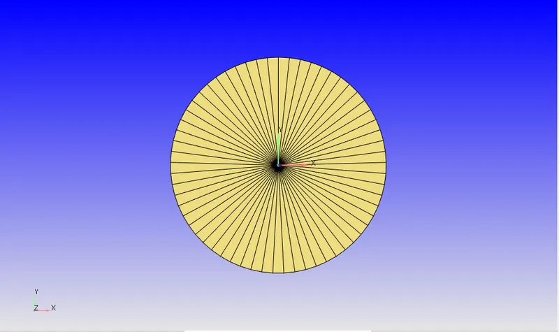
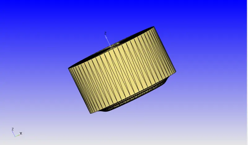
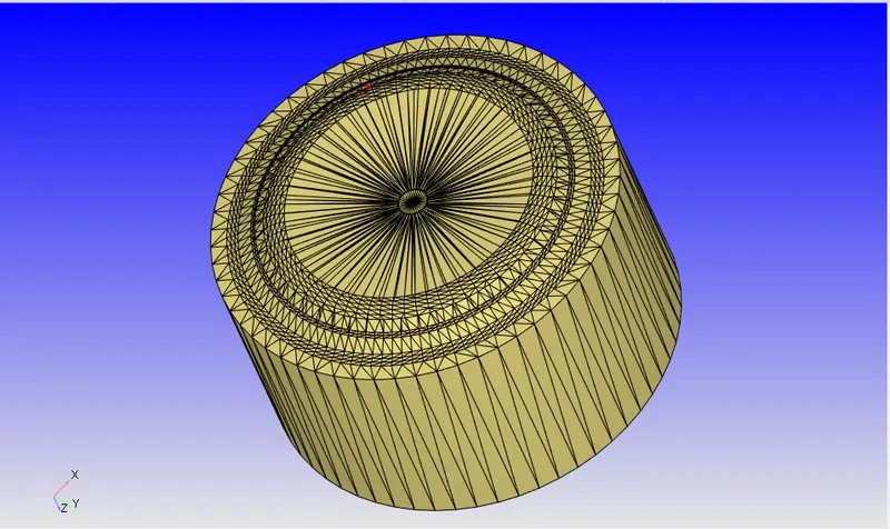
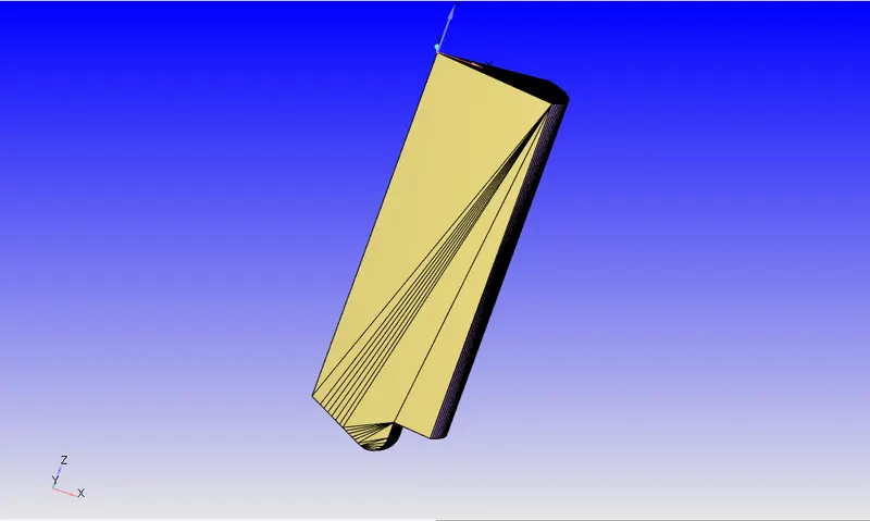
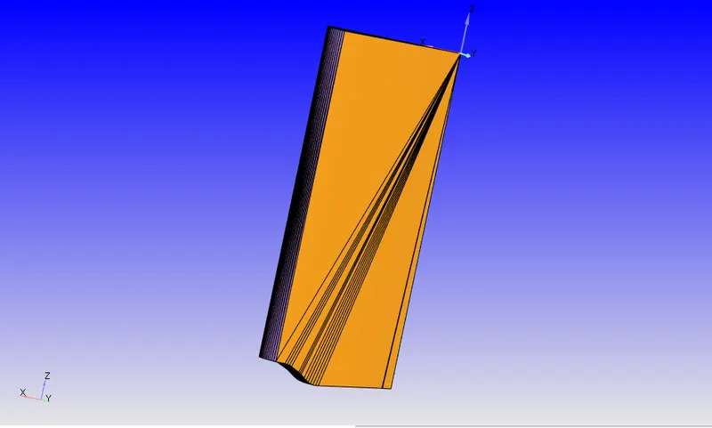
- The combustion simulation in a diesel engine was carried out using sector geometry. The combustion chamber's 360-degree geometry was imported into CONVERGE.
-
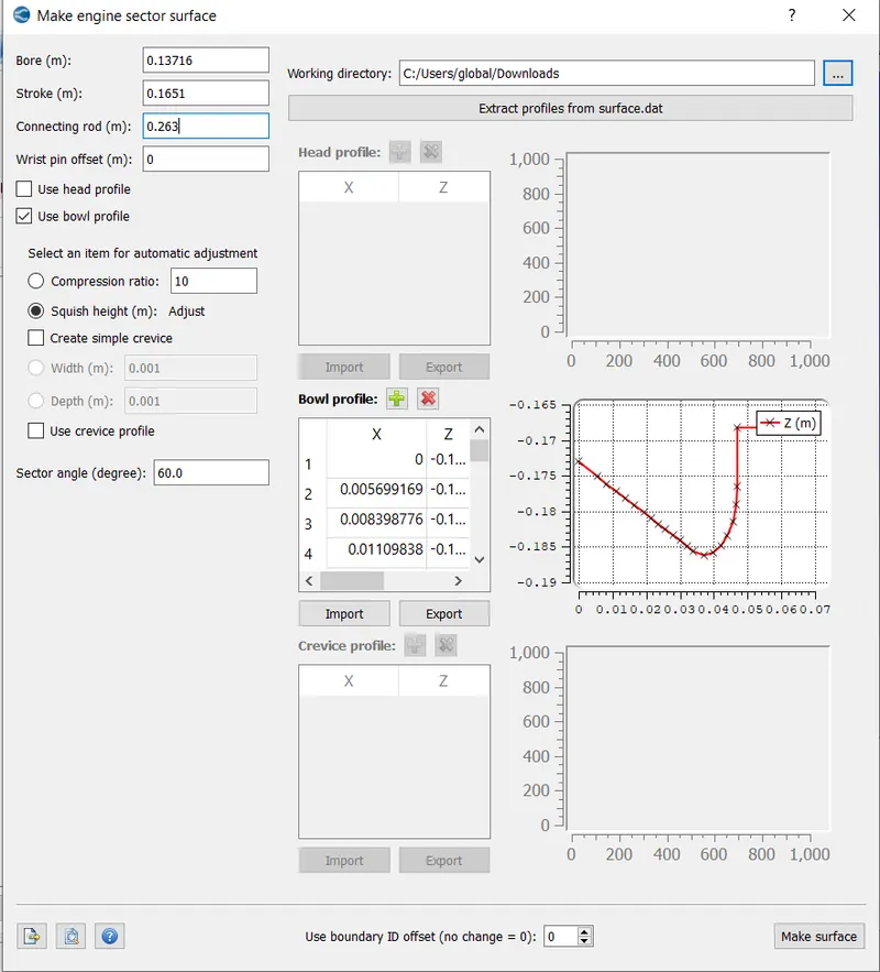
The engine sectors of angle 60 degrees were created for both the omega and open w pistons using the 'Make engine sector surface' option in Tools.
-
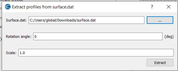
After importing a bowl profile, they make surface command was used.
CASE SETUP:
1. APPLICATION TYPE:
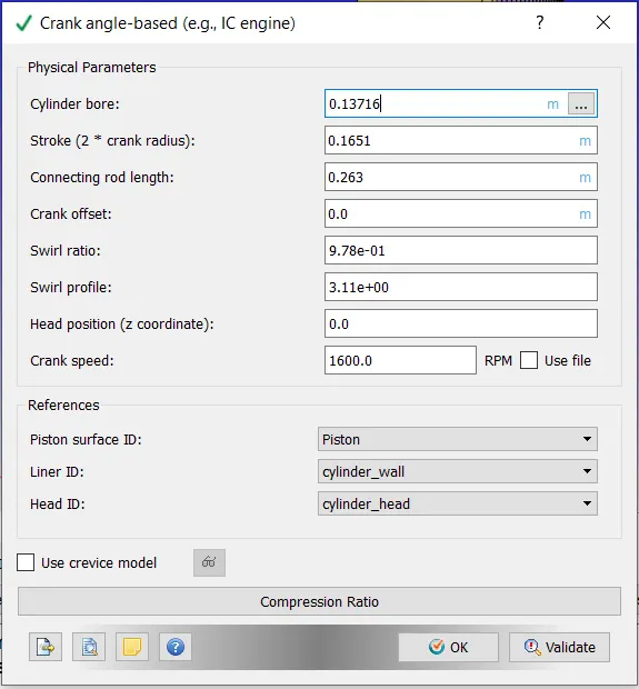
- Crank Angle based IC engine was selected as the application type. Geometric specifications such as bore dia, rpm, and so on were obtained from the Engine Geometric parameters, as shown below.
2. MATERIALS:
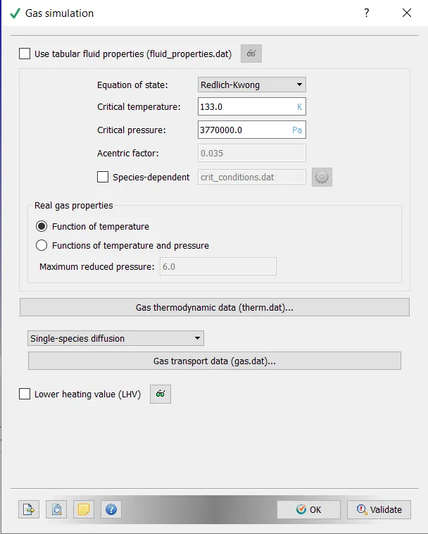
- GAS SIMULATION - Default value,
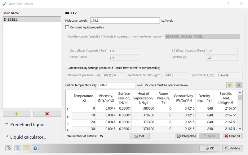
- PARCEL SIMULATION - When we model a simulation that contains fuel spray, the fuel spray is represented as a Lagrangian Parcel. A parcel is a spray model that is based on Langrangian theory. Diesel2 is the fuel spray in this case.
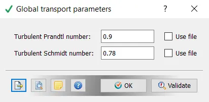
- GLOBAL TRANSPORT PARAMETERS:- Default value;
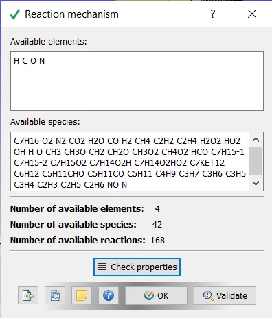
- REACTION MECHANISM:- Values from therm.dat and mech.dat have been loaded into the profile.
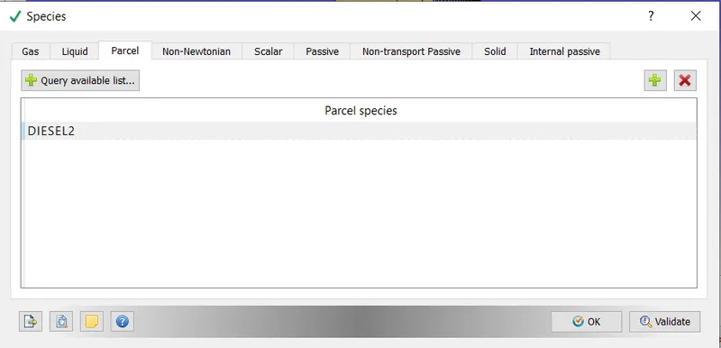
- SPECIES:- Diesel2 has been added to the 'Parcel' category.
3. SIMULATION PARAMETERS:
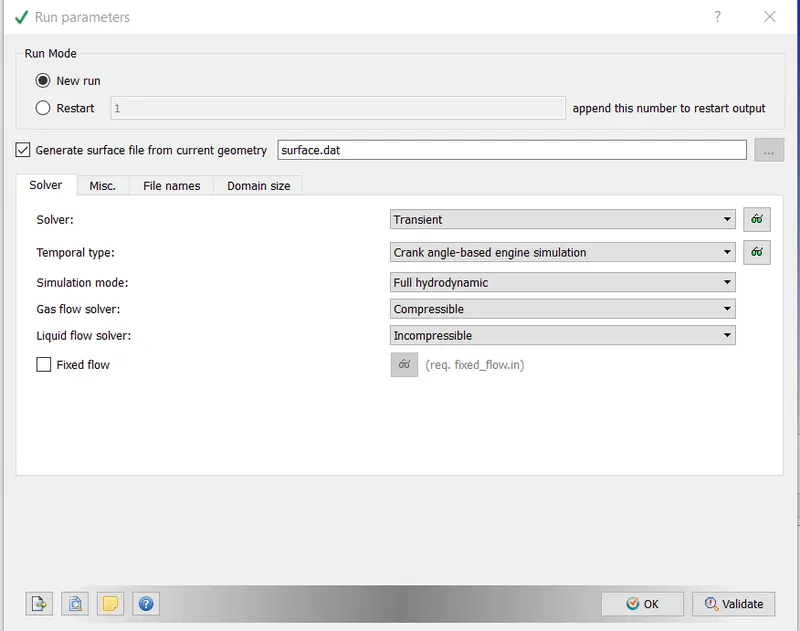
- RUN PARAMETERS:- Full Hydrodynamic Simulation Mode is selected.
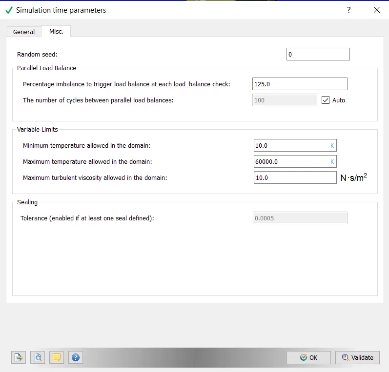
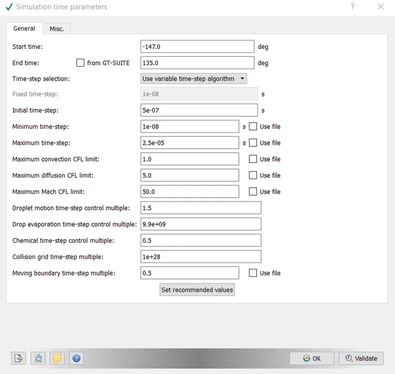
- SIMULATION TIME PARAMETERS:- Values as shown below,
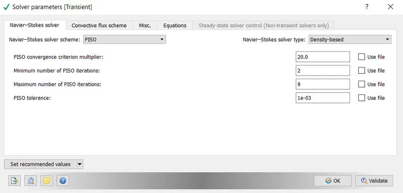
- SOLVE PARAMETERS:- The default PISO scheme and density-based solver were employed.
4. REGIONS AND EVENTS:
- A region is a collection of boundaries that are used to distinguish different areas within the boundary. Regions are useful for many reasons.
- Regions are used to specify initial conditions.
- Control Flow Across Regions (via events)
- Output results are broken down by region.
- Utilize grid control techniques based on regions.
- Organize solutions by region
- Regionalize combustion models
- Determine time steps using CFL numbers specific to each region.
- Events determine when to flow between regions is permitted.
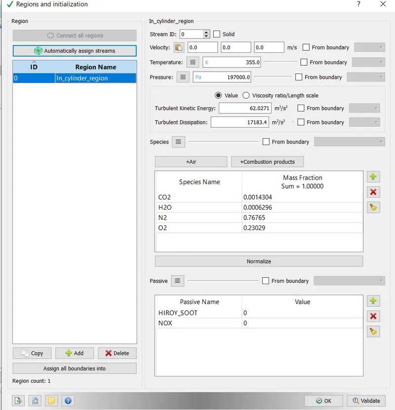
- In this case, four regions have been defined, namely the Cylinder region, Intake 1, Intake 2, and Exhaust regions.
1) Cylinder area:
- 1360 K is the temperature (Value provided in the question)
- 185731 Pa Pressure (The value given in the question)
- For this analysis, the fuel-air mixture was assumed to be lean, with excess oxygen on the product side. This is supported by the presence of O2 in the exhaust gases.
- The following values are provided into species.
5. BOUNDARY CONDITIONS:
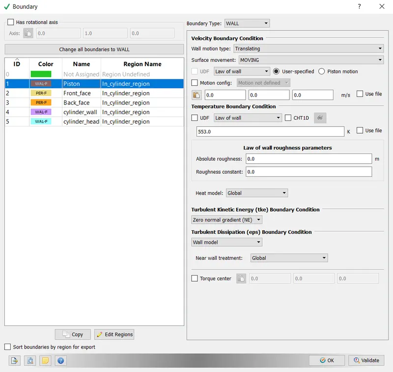
- The ICE engine's components were classified into different regions, as shown below.
-
Piston:- Boundary Type- Wall,
-
Wall Motion Type- Translation,
-
Surface Movement- Moving.
-
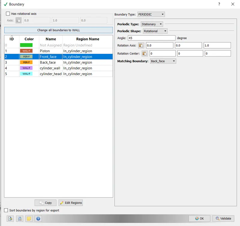
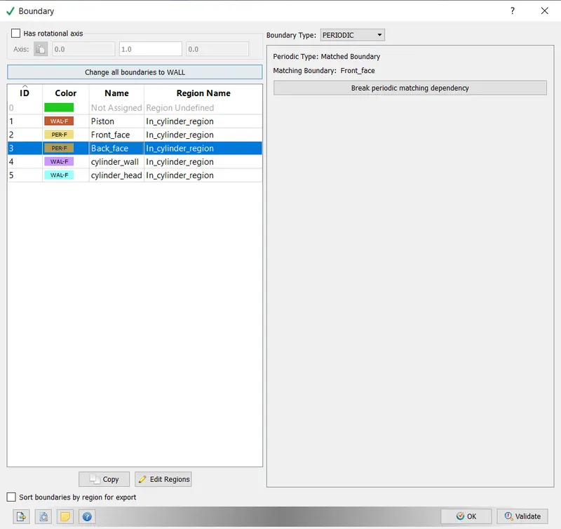
Front Face:
-
Boundary Type- Periodic,
-
Wall Motion Type- Stationary,
-
Surface Movement- Rotational.
-
Back Face:
-
Boundary Type- Periodic
-
Matched Boundary to the front face.
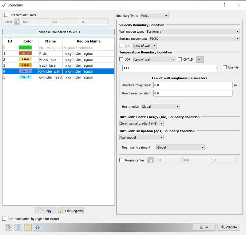
- Cylinder Wall:
-
Boundary Type- Wall,
-
Wall Motion Type- Stationary,
-
Surface Movement- Fixed, Law of the Wall,
-
Temperature Boundary Condition- Law of the wall.
-
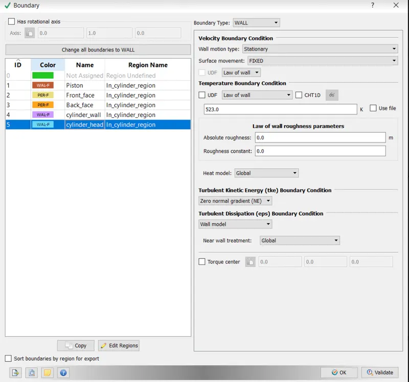
Cylinder Head:
-
Boundary Type- Wall,
-
Wall Motion Type- Stationary,
-
Surface Movement- Fixed.
6. PHYSICAL MODELING:
- SPRAY MODELING:
General Configuration:
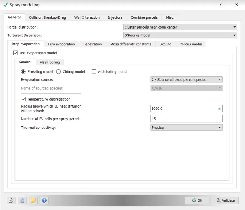
i) Parcel Distribution- Distribute Parcels evenly across the cone.
ii) O Rourke Model of Turbulent Dispersion (For gasoline engines, the O Rourke model gives better results)
iii) The Evaporation Model is enabled.
iv) Frossling model chosen
v) Evaporation source: Select all base parcel species (This implies that IC8H18 (liquid) was converted to IC8H18 (solid) (gas)
vi) Discretization of temperature enabled
vii) Radius of 1000 m above which the 1 D heat equation will be solved
viii) The number of FV cells per spray parcel is 15
ix) Physical thermal conductivity
-Drop Evaluation
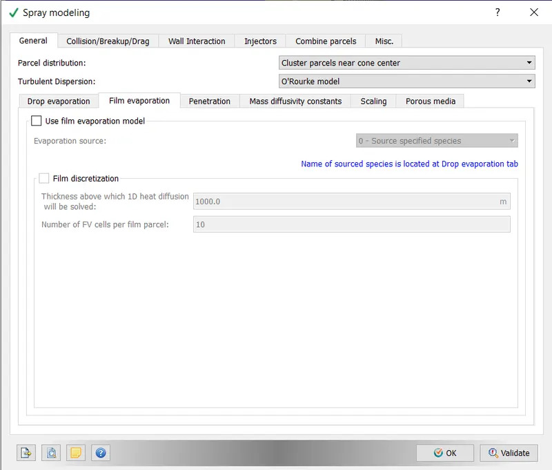
- Film evaporation: Default value,
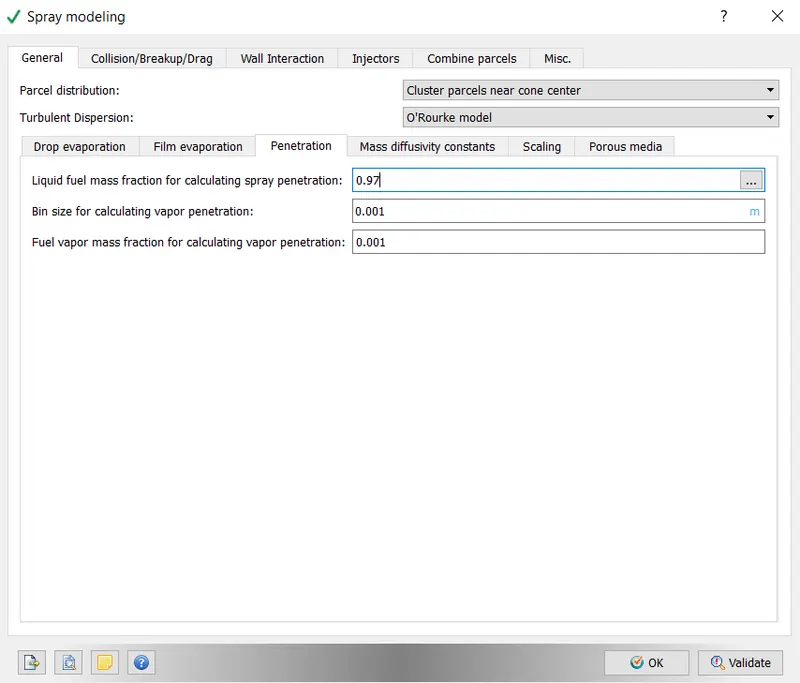
- Penetration: Values as follows,
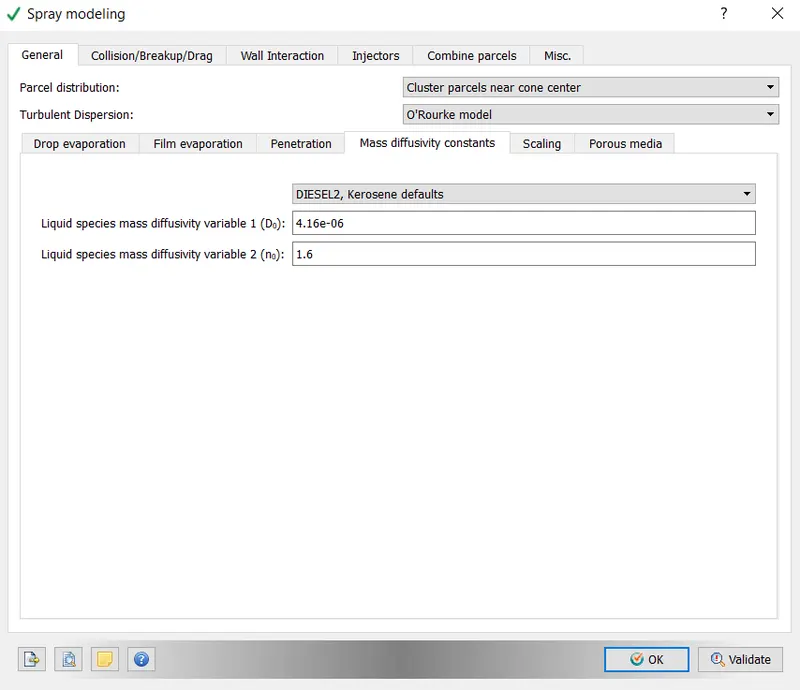
- Mass Diffusivity: Default value for Diesel and Kerosene,
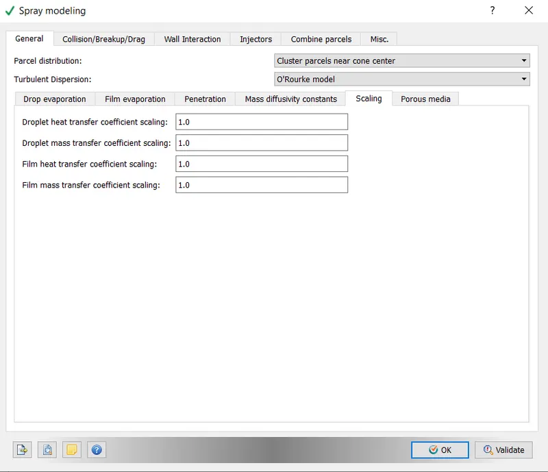
- Scaling: Values as shown,
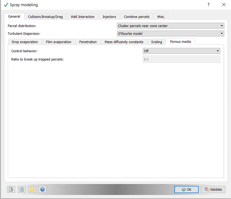
- Porus Media:
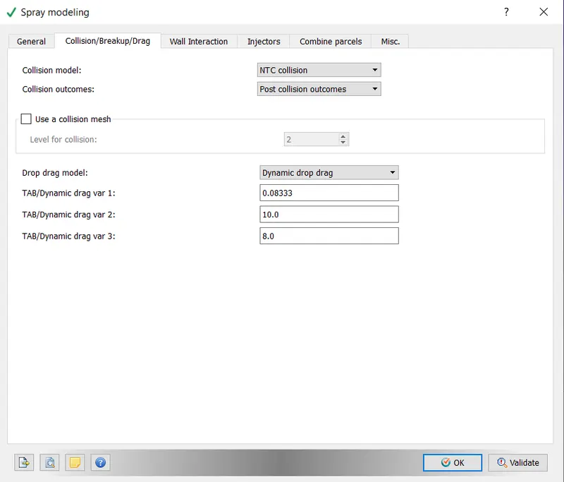
- COLLISION BREAKUP AND MODELLING:
I Collision model: NTC collision is employed.
ii) Collision results:- Post-collision results
iii) The option to use a collision mesh is enabled.
iv) Dynamic drop drag model
v) Dynamic drag values are configured as shown below.
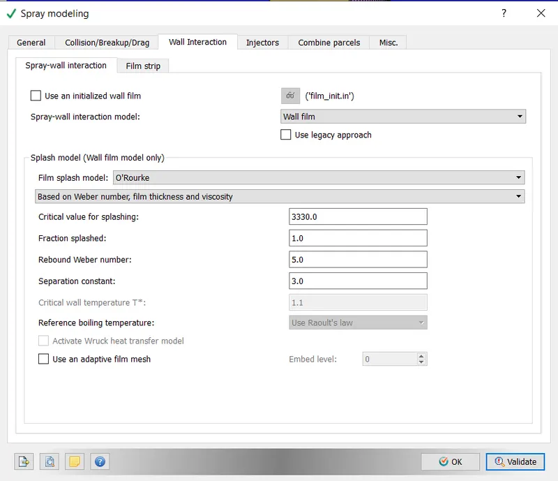
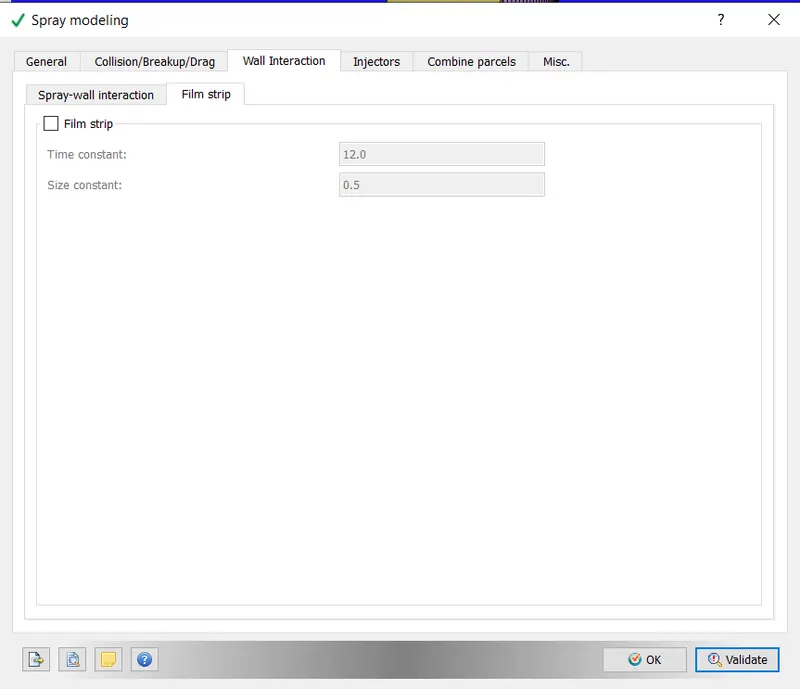
- WALL INTERACTION:
- INJECTOR MODELLING:
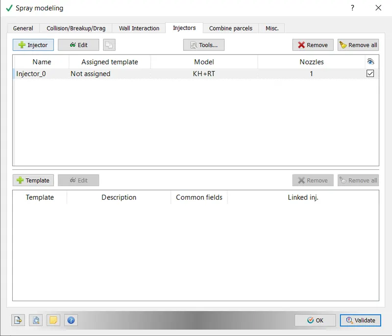
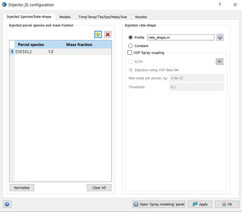
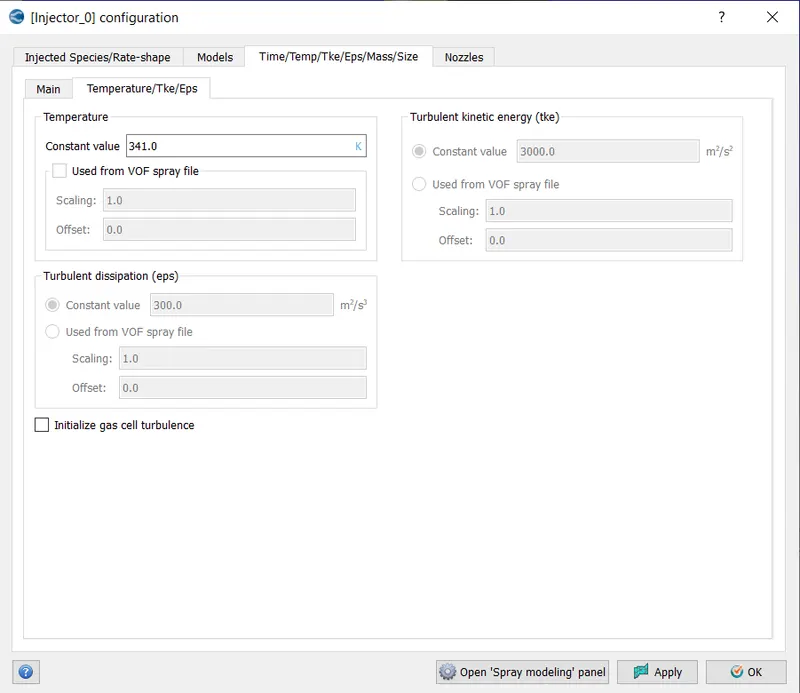
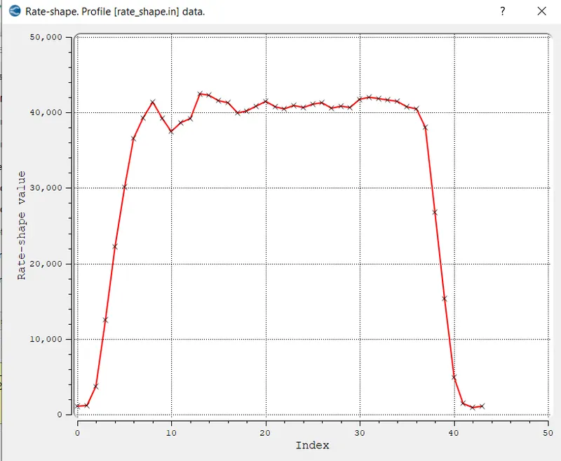
- INJECTOR SPECIES: The parcel species is set to C7H16, and the mass fraction is set to 1.0. Imported injection rate shape profile.
- MODELS:
-
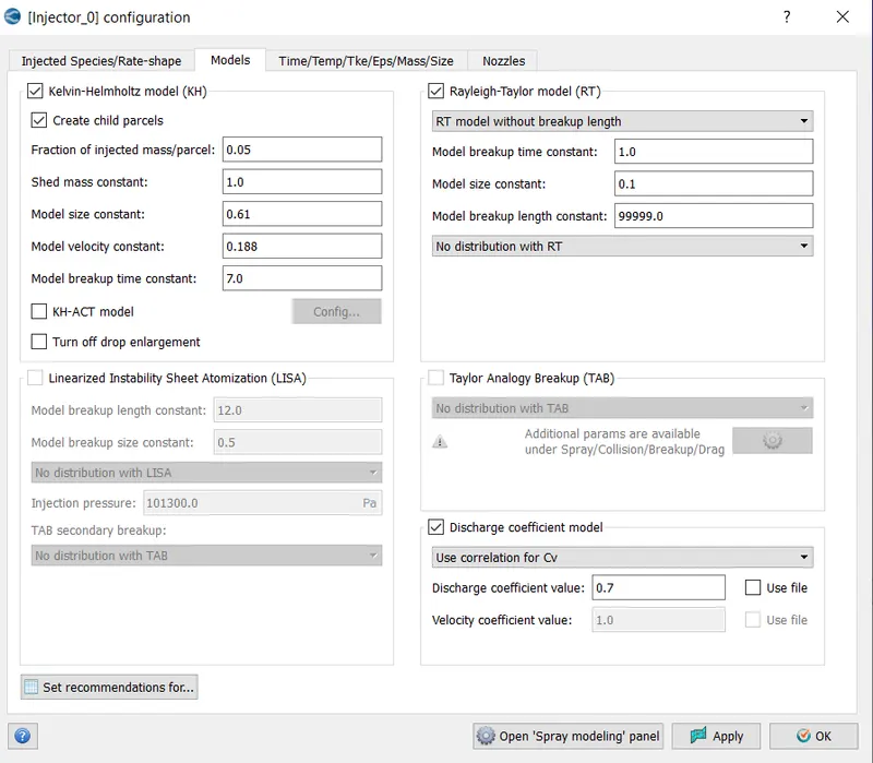
The Kelvin- Helmholtz and Rayleigh- Taylor models were chosen because they are the most commonly used models for solid cone sprays. The default constants have been kept. The discharge coefficient has been set to 0.8. The liquid particle breakup is controlled by the default constants. Although the stability equation governs the process, it does not capture the finer details. The constants control how long it takes for the droplets to break up and the size of the child droplets.
- INJECTOR CONFIGURATION:
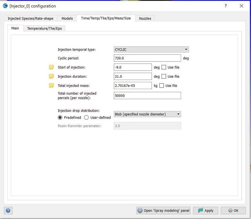
1) Temporal injection type - CYCLIC
2) Cycle time - 720 seconds
3) Injection Start = -9 degrees
4) Injection time = 21 degrees
5) 2.70167 e-05 kg total injected mass
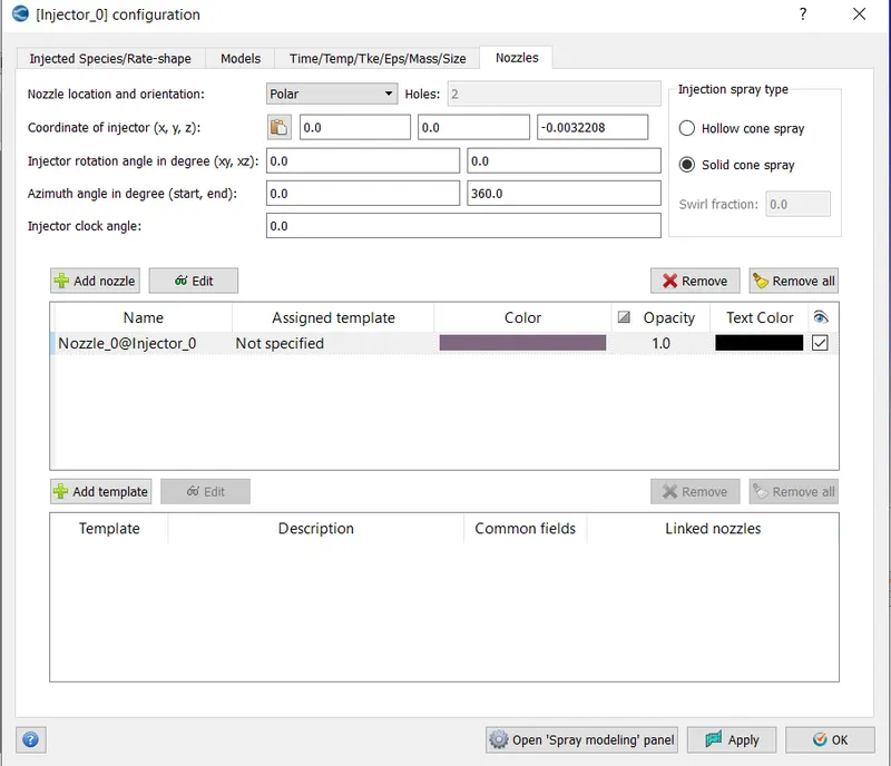
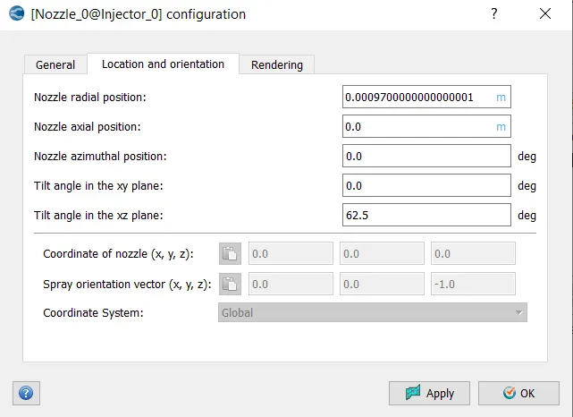
- NOZZLES:
i) Nozzle Location and orientation- Polar,
ii) Injection type - Solid cone spray,
ii) Coordinate of injectors shown as follows,
-
COMPUTATION OF MAXIMUM INJECTION PRESSURE:
-
Peak Injection Pressure = 1097 (bar),
-
Peak Injection Velocity New = 471.45 (m/s).
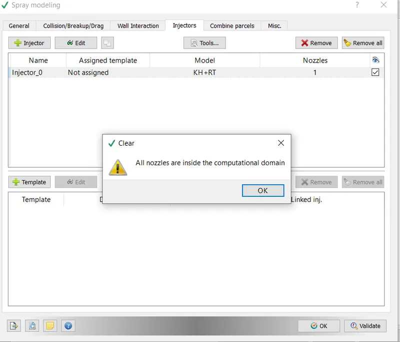
- Nozzle Location Validation To ensure that the newly created nozzles were within the computational domain, the Tools-Validate Nozzle location was chosen, and the following item was displayed.
- COMBUSTION MODELING:
- In an engine, combustion facilitates energy transfer. The SAGE detailed Chemistry Solver is the combustion model used for IC engines. The SAGE solver is the most accurate and predictive way to model combustion. It accurately models ignition and laminar flame propagation.
- Based on the principle of chemical kinetics, the SAGE model calculates reaction rates using local conditions. It determines kinetically limited phenomena such as engine knock and emissions by solving detailed chemical kinetics during combustion. It reads a CHEMKIN-format reaction model and solves ODEs to determine the reaction rate. It also uses the Arrhenius law to calculate the rate of change of species concentration. The Chemistry solver calculates new species mass fractions immediately before solving the transport equation at each time step. CODES were used to solve a system of elementary reactions.

- Solving SAGE equations is a time-consuming process. CONVERGE includes the following options to reduce computational time.
- Raise the minimum cell temperature and mole fraction of HC species to reduce the number of cells in which combustion calculations are performed.
- Use start and end times to constrain SAGE to specific time intervals.
- Restrict SAGE to specific geographic areas.
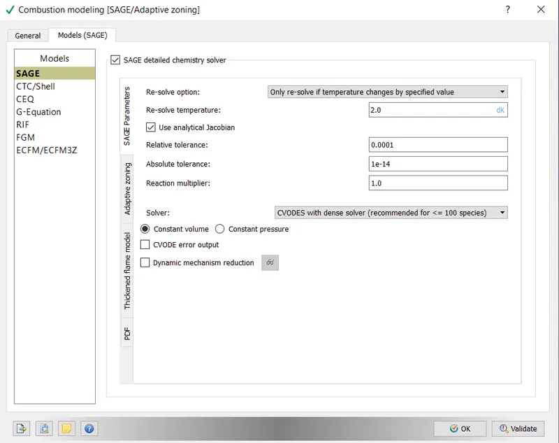
- Change the resolve option to Only resolve if the temperature changes by a certain amount.
- Pass analytically calculated Jacobian to the solver using analytical Jacobian.
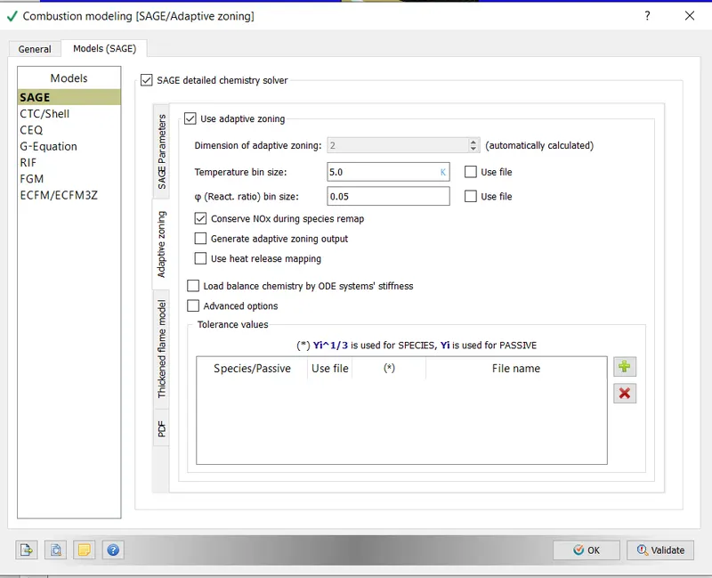
- Multizone models are employed to reduce the number of SAGE calculations.
- The case was set up as shown below for simulation purposes.
- The following parameters were entered into the SAGE detailed chemistry solver.
-
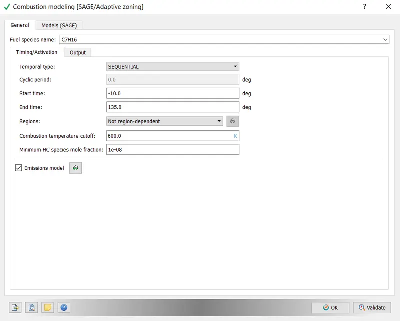
The General settings were configured as shown below. The ignition was programmed to start a few crank angles before ignition. The end time for combustion was determined by taking the opening of the exhaust valve into account.
- EMISSION MODELING:
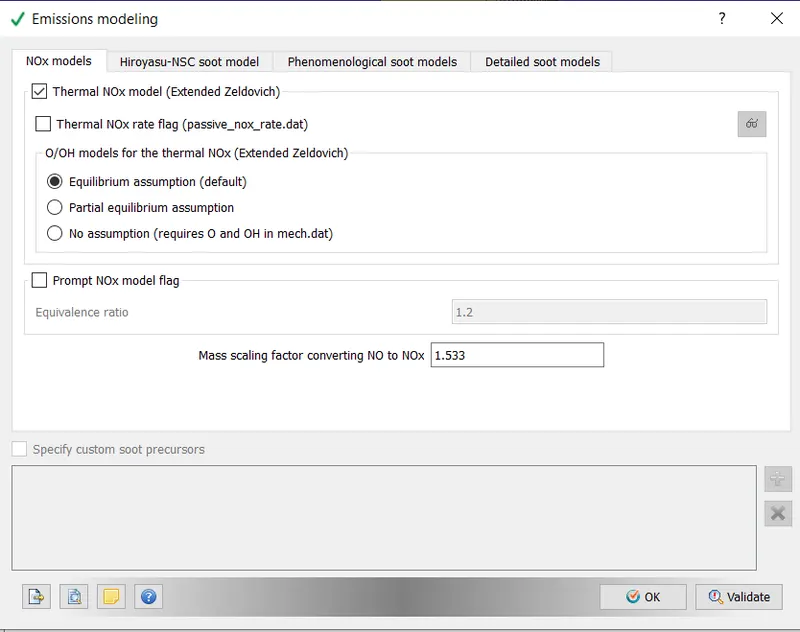
- NOx - Thermal NOx model (Extended Zeldovich chosen),
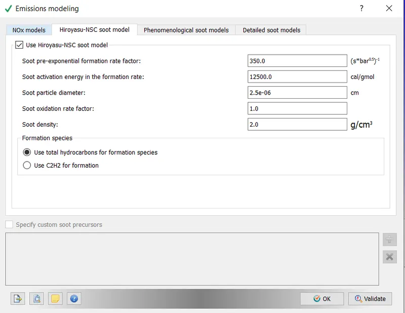
- Hiroyasu NSC soot Model: Values as provided,
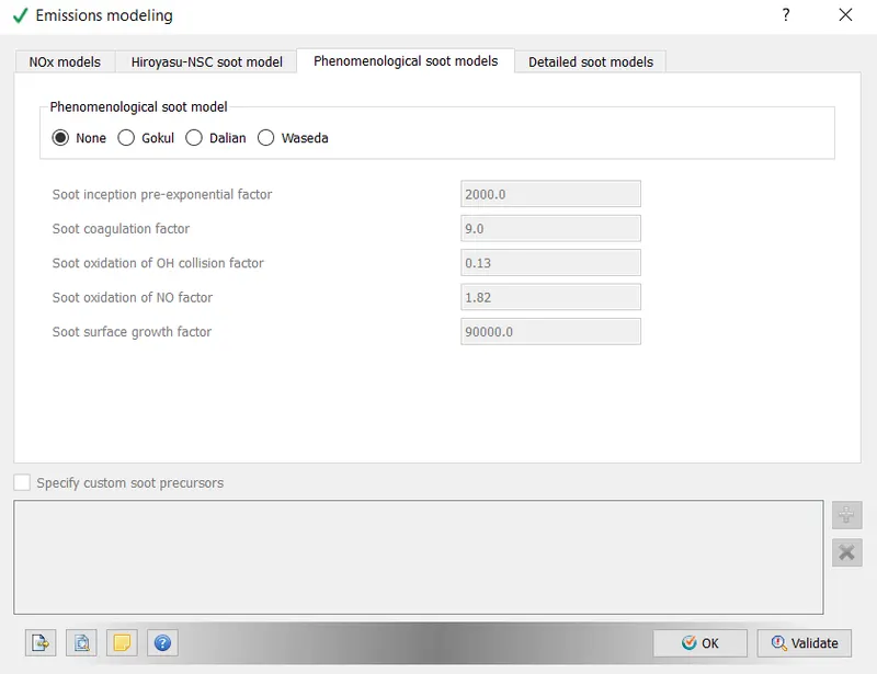
- Phenomenological Soot model,
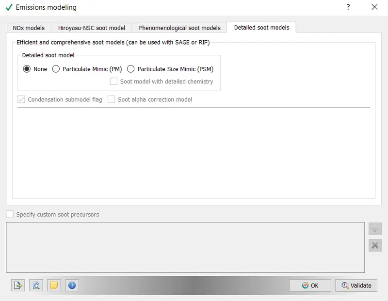
- Detailed Soot Model:
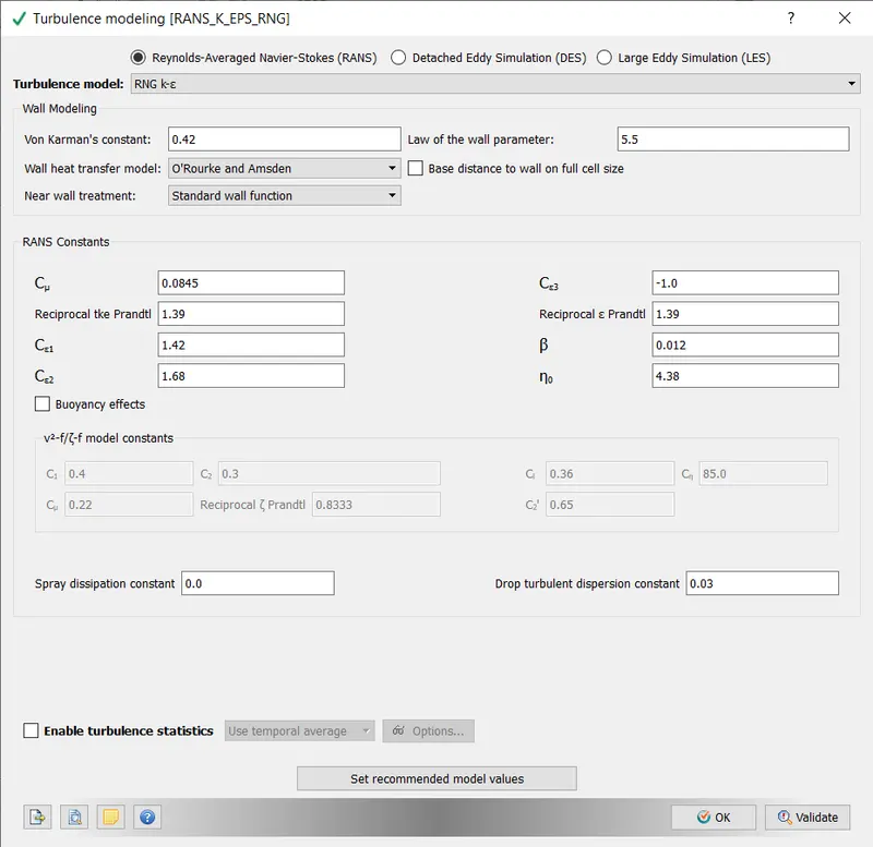
- TURBULENCE MODELLING:
7. GRID CONTROL:
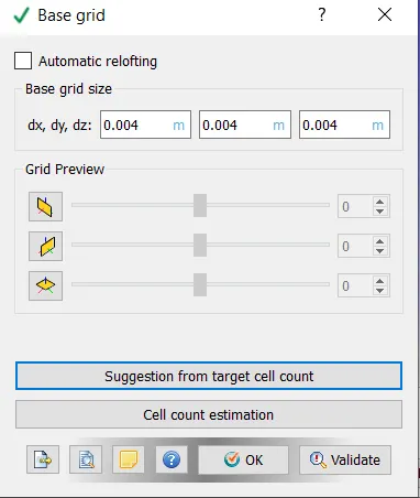
- CONVERGE employs a variety of tools to control grid size during a simulation. Fixed embedding refines a grid at specific times and locations. Grid scaling changes the size of the base grid. Adaptive Mesh Refinement changes the grid based on changing and fluctuating conditions.
- ADAPTIVE MESH REFINEMENT:
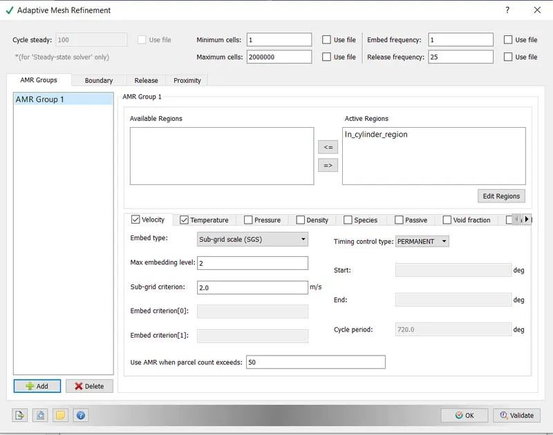
- Two types of AMR are used in the full hydro setup.
1. Velocity:
- The maximum number of embedding levels is 3.
- 1m/s is the SGS criterion.
- The regions would be automatically refined whenever the curvatures exceeded 1m/s.
- Permanent is the type of timing control.
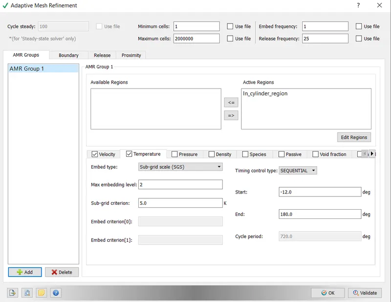
- The temperature.
- Level 3 maximum embedding
- 2.5 K SGS criterion
- The regions would be automatically refined if the curvatures exceeded 2.5K.
- Cyclic timing control type,
- FIXED EMBEDDING:
- Fixed embedding allows for local mesh refinement in domains where finer detail is critical to solution accuracy.
- An embedding scale specifies how CONVERGE will refine the grid in that location.
- dx embed = dx base/2(embed scale)
- Fixed embedding was used at the following location for the Full Hydro setup.
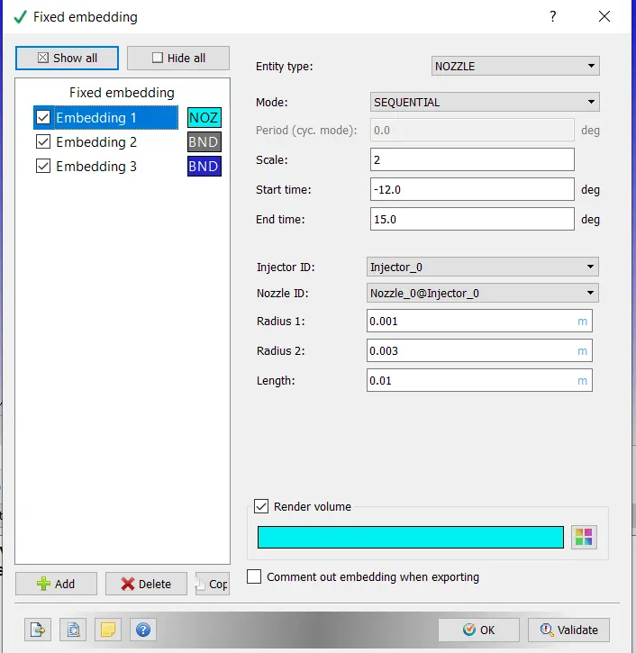
1. The nozzle:
- The nozzle is an entity type.
- Sequential mode
- The scale of Embed = 2
- Grid size at refined locations = 0.004 x 22 = 0.001
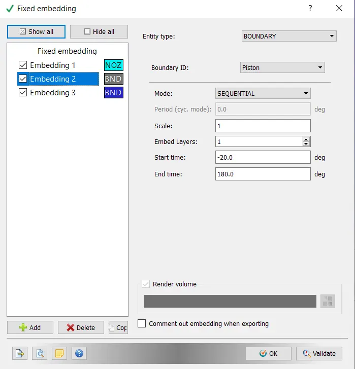
2. Exhaust Valve Angles:
- Boundary entity type
- Piston Boundary ID
- Sequential mode
- Scale of Embed = 1
- Grid size at refined locations = 0.004/2=0.002.
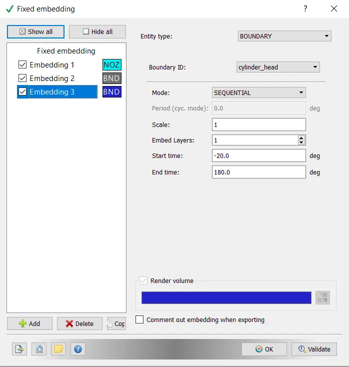
3. Cylinder Head;
- Entity type- Boundary ID
- Boundary ID- cylinder head
- Mode - Sequential
- Embed Scale = 1
- Grid size at refined locations = 0.004/2^1=0.002,
8. RESULTS:
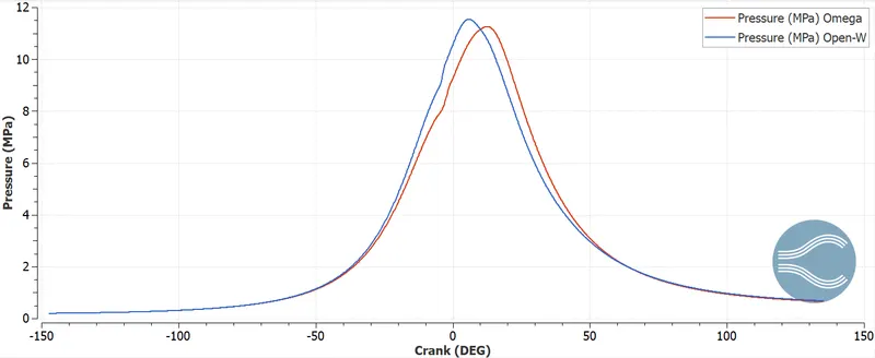
i) MAXIMUM PRESSURE:
- In the plot below, we can see that the omega piston has a slightly higher peak pressure value than the open W piston. This could be attributed to the omega piston's improved compression characteristics as a result of piston geometry.
- VELOCITY CONTOURS:
ii) MEAN TEMPERATURE:
- It is noted that the temperature of the omega piston is higher than that of the open w piston. When comparing the open w piston to the omega piston, a higher temperature can be attributed to more complete combustion in the cylinder.
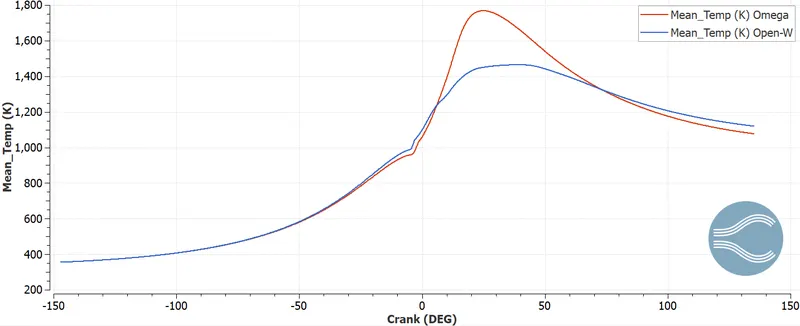
- Based on the above animations, the temperature surpassed in the omega piston is higher than in the open w piston. Because of the improved efficiency of flame spread, effective combustion occurs in the cylinder with an omega piston.
iii) HEAT RELEASE RATE:
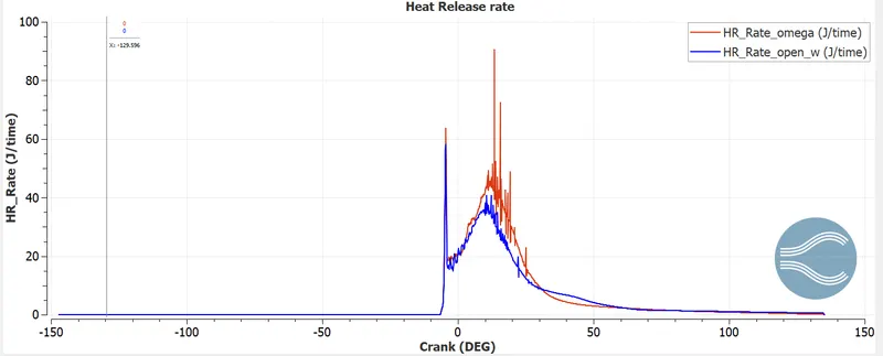
- The magnitude of the heat release rate in the piston with this configuration is marginally higher due to more complete combustion in the cylinder with the omega piston.
iv) INTEGRATED HEAT RELEASE RATE:
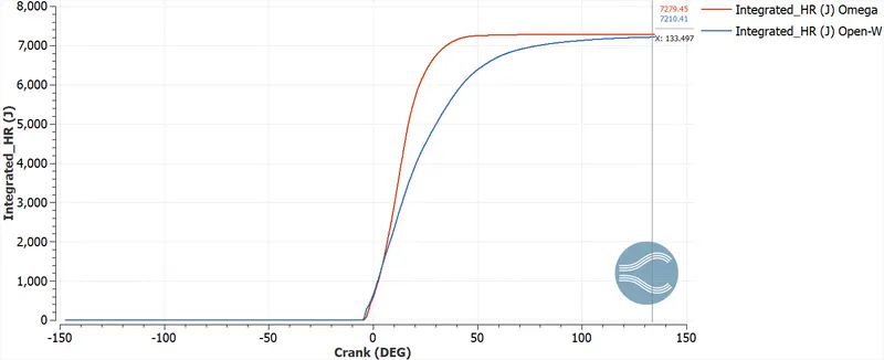
- This calculates the amount of heat generated per cycle throughout the volume This value is higher for pistons with omega configurations for the same reasons stated above.
- EMISSIONS:
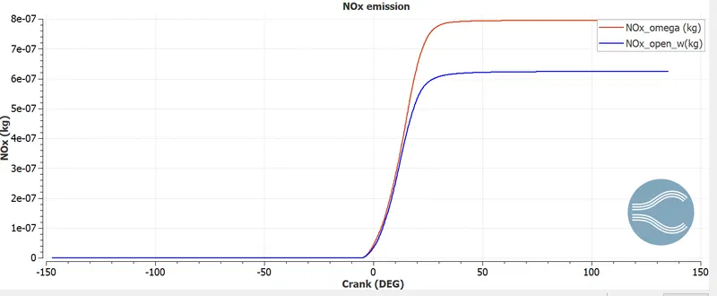
i) NOx - The amount of NOx emitted is greater due to the higher temperature in the omega piston.
ii) CO: - Higher for open_w piston.
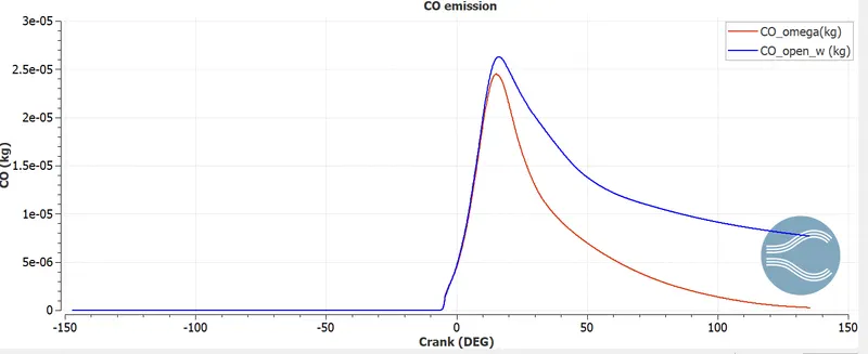
CONCLUSION:
-
In this study, two different Diesel engine piston profiles, the omega profile and the open w piston were compared. The findings are summarised below.
-
It was found that the omega piston produced more complete combustion than the open w piston. As a result, the temperature increased.
-
The unburnt hydrocarbons emitted by the cylinder with the omega configuration were lower than those emitted by the piston with the open w configuration.
-
NOx emissions were higher in the cylinder with the omega piston due to the higher temperature attained compared to the open w piston.
-
When compared to an open W piston, the Omega piston produced more power.