Emission characterization on a CAT 3410 engine and comparing performances of Open W piston and Omega piston using Converge CFD
Aim:-> Setting combustion simulation for diesel engine and comparing result between open W piston and omega piston.
Theory:-
The purpose of typical internal combustion engines is to produce work by converting chemical energy to mechanical energy. In internal combustion engines chemical energy in the fuel is converted by burning or oxidizing the fuel inside the engine. After the heat from combustion causes rapid pressurization of the gaseous combustion products in the combustion chamber, causing them to expand and drive a piston rapidly, which turns a crankshaft to produce mechanical energy.
A diesel engine is a type of an IC engine in which ignition of the diesel fuel is caused by the elevated temperature of the air inside the cylinder due to the mechanical compression and it results in conversion of chemical energy in diesel fuel to rotary mechanical energy. The diesel engine was named after its inventor, Rudolf Diesel who was born in Paris in 1958. Due to ignition method of mechanical compression these types of an engine are also known as compression ignition. The first diesel engine was prototyped in 1893 and originally designed to run on peanut oil. Diesel fuel was so named because it was used to run diesel engines, diesel engines were not named after the fuel, which at the time of the first diesel engine, was an useless byproduct of extracting paraffin and kerosene from crude oil. In 1894 this waste product was finally named "diesel".
 |
Diesel engines work by compressing only the air. This increases the air temperature inside the combustion chamber to such a high degree that atomized diesel fuel injected into the combustion chamber ignites spontaneously. With the fuel being injected into the air just before combustion, the dispersion of the fuel is uneven; this is called a heterogeneous air-fuel mixture. The torque a diesel engine produces is controlled by manipulating air fuel ratio, instead of throttling the intake air, the diesel engine relies on altering the amount of fuel that is injected, and the air-fuel ratio is usually high.
A four-stroke diesel engine resembles a gasoline engine as it works on the four-stroke cycle. The four strokes can be named as- suction, compression, power and exhaust stroke.
 |
When the piston gets down on the air suction stroke, the lower pressure in the cylinder allows a charge of air into the cylinder through the inlet valve which opens just before top dead center. Once the piston has passed the bottom dead center and is beginning to ascend, the inlet valve closes and the upward movement of the piston compresses the air charge in the cylinder causing a quick rise of temperature. Before the second stroke is over, the charge of fuel oil is gradually injected into the cylinder by an injector. The burning of the air-fuel charge makes the gases expand. They push the piston downwards and create the power stroke. Before the piston reached the bottom dead center, the exhaust valve opens and, as the piston goes up again, the burnt gases are forced out through the exhaust valve. Just before top dead center the inlet valve opens and the cycle begins again.
Combustion in the diesel engine differs fundamentally from combustion in the gasoline engine. In the gasoline engine, a more or less homogeneous mixture of air and fuel vapor is compressed and ignited by a spark shortly before TDC, then a flame develops and propagates across the cylinder. In the diesel engine, on the other hand, only air is compressed by the piston and the fuel is injected into the chamber towards the end of the compression stroke. At this point the temperature of the air is high enough to cause the fuel to ignite spontaneously. The time interval between the start of injection of the fuel and ignition of the first portion of the mixture is typically 1 ms; this represents 12° of crankshaft rotation for an engine running at a speed of 2000 RPM. During this time the fuel must enter the cylinder, break down into smaller droplets, vaporize and combine with the air to form a mixture which lies within the flammability limits and is at a sufficiently high temperature for self-ignition to occur. The mixing process between air and fuel is therefore of critical importance to combustion: this mixing is obviously dependent on the characteristics of the fuel spray. Only in large diesel engines is it possible to achieve adequate mixing by spraying fuel into stationary air: in most cases it is necessary to move the air past the fuel spray and under these circumstances the air motion is clearly important too. If the movements of fuel and air are not matched satisfactorily, then the efficiency of combustion will suffer, with a consequent deterioration in power output and fuel consumption and an increase in the levels of exhaust emissions, both particulate (smoke) and gaseous.
Spray modelling:
CFD modeling of spray injection and mixture formation in an IC engine is a multi-component multiphase problem which involves liquid fuel and the various species that participate in mixture formation. Generally, the gas phase is treated in an Eulerian fashion and liquid phase is treated in Lagrangian fashion. The interaction between the phases is accounted for by source terms in the Eulerian gas phase.
A well known and extensively used approach in spray modeling is the Discrete Droplet Method (DDM) which treat the spray in a Lagrangian framework. This method solves ODE’s for momentum, heat and mass transfer of a cluster of particles referred to as parcels. Each parcel is represented by a group of non-interacting droplets with identical properties. A large number of parcels combinedly defines spray behavior.
When fuel is injected through nozzle in intake manifold, it is in form of liquid spray (made of number of droplets) those droplets get interacts with the surrounding air (Air coming from inlet), a specific amount of drag force is generates on spray droplets. This action causes disturbances and due to propagation of such disturbances spray breaks up i.e., atomization happens. A liquid gets break down into small parcels which is termed as primary breakup and these small parcels again break up even further to tiny parcels is termed as secondary breakup.
 |
 |
When spherical parcels interact with air, their shapes get affected by flow velocity of air which results in varying speed of vaporization this effect is called as drop drag. And reduction in droplet size is described with evaporation of parcels. Experimentally it is seen that the evaporation of a droplet follows a d2 law which is as given follow.
`d^2 = d_0^2 - betat`
Where, `d_0 ="Initial drop diameter"`
`d="Diameter of drop after evaporation at time t"`
`beta="Coefficient of evaporation for fuel"`
The coefficient `beta` is function of temperature, pressure and chemical concentration of fuel.
O'Rourke model:
The model of O’Rourke considers binary collisions and collision can only occur if and only if the two parcels are situated in the same computational cell. The expected number of collisions is expressed by the following relation.
`barn = |U_(d1)-U_(d2)|pi(r_1+r_2)^2n_2/(V_"cell")Deltat`
Here larger parcel is denoted by index 2 which is also known as collector and smaller parcel denoted by index 1 is known as droplet. 'U' is relative drop velocity and 'r' is radii of drop. `n_2` is number of droplets in collector. `V_"cell"` is cell volume and `Delta t` is time step. For this model the probability of collision follows Poisson's distribution.
Sage combustion model:
Converge provides varieties of solvers to simulate the combustion phenomenon in an IC engine. Converge provides SAGE detailed chemistry solver to simulate combustion in detailed manner. It uses local conditions to calculate reaction rates based on the principles of chemical kinetics. This solver is fully coupled to the flow solver, but the chemistry and flow solvers parallelize independently of one another, which speeds up the simulation. With the appropriate mechanism, the SAGE solver can predict a wide range of cases e.g., premixed, non-premixed, partially premixed, multiple fuels, emissions modeling. Though the SAGE is detailed and time consuming, Converge included some features like ‘multizone’ to reduce computational cost and time.
Emissions in Diesel engine:
Climate change is being counted as a global environmental threat caused by people. It is seen as the second most serious issue that the world faces and has brought about results that affect life adversely. Diesel engines are considered as one of the largest contributors to environmental pollution caused by exhaust emissions, and they are responsible for several health problems as well. Many policies have been imposed worldwide in recent years to reduce negative effects of diesel engine emissions on human health and environment. Many researches have been carried out on both diesel exhaust pollutant emissions and aftertreatment emission control technologies. The four main pollutant emissions from diesel engines are carbon monoxide (CO), hydrocarbons (HC), particulate matter (PM), nitrogen oxides (NOx) and to control these emissions systems like diesel oxidation catalyst, diesel particulate filter and selective catalytic reduction are uses.
Pollutant emissions have a rate of less than 1 % in the diesel exhaust gas. NOx has the highest proportion of diesel pollutant emissions with a rate of more than 50 %. After it, PM has the second highest proportion in pollutant emissions. Because diesel engines are lean combustion engines, and the concentration of CO and HC is minimal. Besides, pollutant emissions include a modicum of SOx depending the specifications and quality of fuel. It is produced by the sulfates contained in diesel fuel. For the present, there is not any aftertreatment system like a catalytic converter to eliminate SOx. Nowadays, most of oil distributors and customers prefer ultra-low sulfur diesel (ULSD) for diesel engines to prevent harmful effect of SOx.
-
Carbon monoxide results from the incomplete combustion where the oxidation process does not occur completely. This concentration is largely dependent on air/fuel mixture and it is highest where the excess-air factor (λ) is less than 1.0 that is classified as rich mixture.
-
Hydrocarbon emissions are composed of unburned fuels as a result of insufficient temperature which occurs near the cylinder wall. At this point, the air–fuel mixture temperature is significantly less than the center of the cylinder.
-
Particulate matter emissions in the exhaust gas are resulted from combustion process. They may be originated from the agglomeration of very small particles of partly burned fuel, partly burned lube oil, ash content of fuel oil, and cylinder lube oil or sulfates and water.
-
High temperatures above 1,600 °C in the cylinders cause the nitrogen to react with oxygen and generate NOx emissions. So, it will not be wrong to say that the major influences of the formation of NOx are the temperature and concentration of oxygen in the combustion.
Problem setting:-
The below figure shows combustion chamber geometry which is in closed valve condition (both inlet and exhaust valve are closed).
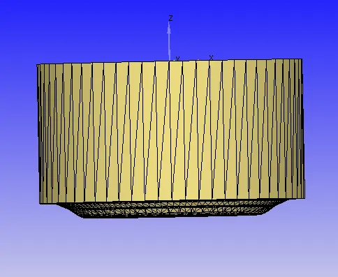
As in diesel engine there is one injector which is located centrally and 6 nozzles which are located at equal angle. (Hence the geometry can be considered as axisymmetric along central axis of injector) To run the simulation for entire 360degree, it will consume a lot of the computational time and also acquires a lot of memory. So, in order to save the time and memory we need to consider sector of the geometry which can be possible by using ‘Make engine sector surface’ tool in converge CFD.
Engine geometrical parameters:
- Bore =0.13716 m
- Stroke = 0.1651 m
- Connecting rod length = 0.263 m
- RPM = 1600
Open W type piston sector generation:
As we have complete 360 degree geometry of open W type of piston we need to convert it in sector form. So, in order to convert complete geometry in sector form we will use same tool of "Make engine sector surface" and in that tool choose option of "Extract profile from Surface.dat file". This will allow us extract surface files. We need to use correct surface data file, then after extracting we will get 3 to 4 different files which consists of geometry profile data of various parts in different files like bowl profile, head profile, etc.

Import bowl profile obtained previously from extracting surface profile. Also provide engine geometrical parameters. As we have considered number of nozzles are 6 which makes 360/6=60. Hence, use sector angle of 60. And created sector is shown as below.

Omega type piston sector generation:
Omega type piston is bit different from open W piston. Both of the open W piston and omega type of pistons have their own advantages and dis advantages. Now let us prepare omega piston. It is also can be prepared by using same tool of "Make engine surface".

As we have bowl profile for omega piston, let us import bowl profile of omega piston. Before importing bowl profile, we need to give engine geometric parameters like bore, crank length and stroke. As the engine is CI type of engine so provide high compression ratio with sector angle of 60 degree. The following figure shows sector of omega type of piston.

When we create sector using "Make engine surface" tool it will automatically create boundaries. We just need to rename boundaries as meaningful name to ease in problem setting and minimize confusion.

The above figure shows naming of boundary faces and its region.
Case setup process:-
- Select the application as crank angle base ic engine.
- Open crank angle based window from case setup tree.

User need to enter values of engine geometrical parameters and crank speed. Also need to specify reference part / surface IDs. Then click on compression ratio, it will open new window like following.

Here we need to provide target value of compression ratio, and as we are using engine sector so need to select engine sector option.
Material:
- Open gas simulation window under material in case setup tree. Then click on "Gas thermodynamic data" which will allows us to import species thermodynamic property file which is in form of "therm.dat" file.
- Enable parcel simulation. And open simulation window.

Use predefined liquid and select Diesel 2 from option and validate it.
- Then validate global transport parameters.
- Then open reaction mechanism window and import mechanism file named as "mech.dat".

After importing mechanism file check properties and validate it.
- As we have already imported species so we need to only add parcel material. So open species window and open parcel tab.

Add parcels species as Diesel by adding it from query available list and validate it.
Simulation parameter:
- Open run parameter window. In current case use full hydro simulation which includes solving of Navier Stokes equation.

Also use solver as transient without fail. And then set simulation time parameters as follow.

Use initial time step of 5e-7 Seconds for simulation. Keep maximum diffusion CFL number as 5, then validate these values. And then open solver parameter window to edit.

Use density based solver.
Region and initial conditions:
- Prepare user defined region with following properties which is considered as combustion chamber region of and IC engine.
Temperature = 355 (k)
Pressure (Static) = 197000 (Pa)
Turbulent Kinetic energy = 62.0271 `(m^2 / s^2)`
Turbulent Dissipation = 17183.4 `(m^2/s^2)`

Need to add species. Combustion chemical equation is given as-
`C_7H_16+11(O_2+3.76N_2)<=>7CO_2+8H_2O+41.36N_2`
And add passive species as per above figure.
Boundary conditions:
- Now let us start with boundary condition definition.

Use region as in-cylinder region which was defined by us previously.
- Piston:
- Boundary type - Wall
- Motion type - Translating
- Extra info - Piston motion
- Front face:
- Boundary type - Periodic
- Periodic type – Stationary
- Periodic shape - Rotational
- Angle of Sector - 60 degree
- Matching boundary – Rear_face
- Rear face:
- Boundary type - Periodic
- Periodic type – Matched boundary
- Matching boundary – Front_face
- Cylinder wall:
- Boundary type – Wall
- Wall motion – Stationary
- Temperature - 433 k
- Temperature wall boundary - Law of wall
- Cylinder head:
- Boundary type – Wall
- Wall motion – Stationary
- Temperature - 523 k
- Temperature wall boundary - Law of wall
Physical modeling:
- Now open physical models then include combustion modelling and spray modelling by selecting check box.
Spray modelling:
- Now start with spray modelling.
- Provide general settings of spray modelling as per following figure.

Choose parcel distribution in nozzle, for current condition it is set to 'Even parcel distribution throughout the cone'. Also Set turbulent dispersion model to 'O'Rourke model'. Under drop evaporation model, provide evaporation source as given in above figure and give source as `C_7H_16`. One can use temperature discretization for parcels which definitely increase simulation accuracy. In our case to as computation cost is major constraint so we have set very high radius value for drop which results the problem remains unsolved for temperature discretization.
- Now open 'Collision/Breakup/Drag' tab under spray modelling. Set Collision model as 'NTC collision' and ask for 'post collision outcomes'. Uncheck collision meshing and use 'Dynamic drop drag' as drop drag model.

And then in wall interaction tab use spray wall interaction model as "Rebound / slide". The reason behind choosing rebound model is in current case we are considering sector of engine.
- Then open injector tab and add injector.
- Then start editing injector properties. Add Parcel species as "Diesel 2" and import file named as 'rate shape.in' which provide profile for injector rate as follows.

Here we are providing trapezoidal rate shape. It is cyclic and came in action at time of injection.
- Then open up model tab for injector. Check on 'Kelvin Helmholtz model' and 'Ryleigh Taylor model'. Also turn on 'Discharge coefficient model' with discharge coefficient value of 0.7. Then click on set recommendation for and select 'Diesel' which provide reference constant values of above model for Diesel.

All of the above model consists of constants which control the parcels breakup. A particular equation known as the Dispersion Relation predicts time required for a particular parcel to become unstable. Size constants occur are also important criteria because manipulating it may increase or decrease the time taken for the break-up of drop and also increase or decrease the size of the child droplets.
- Provide values for injection time as per above injection parameters.

After injector let us set nozzle.

Add nozzle and edit settings of nozzle.
 |
 |
Validate spray modelling and check for any errors if there are any eliminate those.
- Under the spray modelling there are some tools. Select tool "Validate nozzle location" which will show user that nozzles are inside computational domain or not.
- Choose another tool named as "Spray rate preview", so we will get-
Initial data setup from 'Injector_0'
DIESEL2: interpolated density for 341 (K) is 848 (kg/m^3)
********************************
Inj dur_inject = 21 (CA)
Inj dur_inject = 2.1875 (ms)
Peak Injection Pressure = 1097.05 (bar)
Peak Injection Velocity Old = 356.064 (m/s)
Peak Injection Velocity New = 471.45 (m/s)
It is visible that we obtain peak pressure and velocity for injection at provided injection parameters.
Combustion and emission modelling:
- Choose combustion model as SAGE model. Cause a chemical reaction mechanism in combustion is a set of elementary reactions that describe an overall combustion. For the different fuels, mechanism can be changed to model complete combustion. SAGE model in converge calculates the reaction rates for each elementary reaction and CFD solver will solves the transport equations. So, SAGE model can be prepared as-

And then select fuel species as `C_7H_16` and provide combustion timing parameters as-

And enable emission model.
 |
 |
Validate modelling and check for any errors if there are any eliminate those.
Turbulence modelling:
- Use RNG K-epsilon as turbulence model.
Grid control:
- Use base grid of 0.004m in all X, Y and Z direction.
- Provide velocity and temperature AMR.

Pick subgrid criteria of 2 and maximum embedding level of 2 for velocity AMR and keep it permanent.

It is visible in cell count plot that after some time the cell count is increasing, the reason behind it is AMR. Adaptive Mesh Refinement (AMR) automatically adjusts the grid at each time-step. By refining the grid only when and where it is needed, CONVERGE minimizes the cell count while accurately capturing important flow phenomena. Due to AMR embedding of 2, the cell again split in half dimension. Like here We have restricted till 2 layers only so at first layer the mesh size would be 0.8/2 = 0.4m and again it will divide into half for next layer i.e., second layer. The size for second layer will be 0.4/2 = 0.2m.

Pick subgrid criteria of 5 and maximum embedding level of 2 for velocity AMR and keep it cyclic from -12 degree to 180 degree.
- Also provide fixed embedding at required zones as-
 |
 |
 |
Thus, by providing fixed embedding as shown in above figure we get smooth contours which is seen in animation.
Output and postprocessing:
- Select post variables for post processing.
- Update output files and writing intervals.

Time map:
 |
- Then validate case setup to check problems in setup, if find any resolve those problems.
- Then solve it using command line such as Cygwin.
- When simulation get over convert result files in to Parview VTK binary format to postprocess result data using Paraview.
Result:-
 |
 |
From the above mesh elements data it is seen that how number of cells are varying with respect to movement of piston. As embedding and adaptive mesh refinement is provided, it results in smooth contour of result and also reduces numerical smearing.
 |
 |
 |
 |
As we know that work done is calculated graphically by using P-V diagram, the area under P-V diagram is considered as work done. From observing above PV diagram, we can seen that area under PV curve of omega piston is more than area under PV curve of open W piston which indicates higher work done of omega piston engine than open W piston engine. This can be cross checked in engine performance calculator.
From the above plot of volume, it is clear that for both of the piston engines the volume is similar. And from the mean in-cylinder pressure plot it is seen that for the omega piston the pressure is minimum than open W piston.
 |
 |
 |
 |
From the above plots and animation, it is visualize that how incylinder temperature is varying with crank angle i.e., position of piston. The peak temperature point shows that the start of ignition inside combustion chamber of engine. For the omega type of piston mean temperature is more than open W type of piston. The maximum temperature of omega piston result in high heat rate and also High NOx emission than open W piston which can be observed in heat rate plot and NOx emission plot. Also fuel mass plot shows mass of fuel injected inside combustion chamber.
 |
 |
 |
 |
 |
The above plots shows that variation of emission particle's weight with respect to crank angle. The comparison can be visualize in above plots for open W piston type and omega piston type. Soot is one of the most hazardous emission which is in black color. Soot particles forms during incomplete combustion from precursor molecules such as acetylene. It consists of agglomerated nanoparticles with diameters between 6 and 30 nm. For the open W piston soot emission are more than omega piston. From another plot of NOx emission it is seen that using omega piston emits more NOx than open W piston. NOx is produced from the reaction of nitrogen and oxygen gases in the air during combustion at high temperatures. From the plot of HC emissions, it is seen that the HC emissions are much higher in case of open W piston than the omega piston. The analysis in some research paper shows that there are two main sources of HC in diesel engines. One is due to the volume of fuel in the sac and holes of the injection nozzle and the other is from fuel premixed to leaner than lean limit conditions. CO results from incomplete combustion of the fuel due to local areas with shortage of air supply. In a normal compression ignition engine, the excess air ratio is larger than 1 and thus the CO emissions are generally low. The CO emissions for the open W piston are higher than the omega piston and the emissions are dropped immediately after the raise.
Engine rotations are 1600RPM, to convert it into RPS,
`RPS=(RPM)/60`
`:.1600/60=26.6667" RPS"`
So, when 1 revolution takes place, it covers 360 degrees.
Hence, for 26.6667 rotations-
`26.6667xx360=9600`
Which means in 1 second 9600 Degrees are covered.
Let us compute time need to travel 1 Degree.
`:.1/9600=1.04167e^-4`
Hence to cover 1 degree we need 0.104167 milliseconds.
For open W piston:
 |
| Fig: Engine performance for open W piston |
Gross work = 3028.53 Nm
Duration in degree = 270.156,
As we know, for 1 degrees we need 0.104167 milliseconds,
Then for 270.156 degrees we need to calculate time as.
Hence, `270.156xx1.04167xx10^(-4)`
`:.0.02814125Sec`
So power can be calculate as-
`Power="Work"/"Time"=3028.53/0.02814125`
`Power=107618.887J=107.619KJ`
`Power = (2piNT)/60`
`:.T=(107.619xx60)/(2pixx1600)=642.3030Nm`
For omega piston:
 |
| Fig: Engine performance for omega piston |
Gross work = 3409.28 Nm
Duration in degree = 270.171,
As we know, for 1 degrees we need 0.104167 milliseconds,
Then for 270.171 degrees we need to calculate time as.
Hence, `270.171xx1.04167xx10^(-4)`
`:.0.0281428125 Sec`
So power can be calculate as-
`Power="Work"/"Time"=3409.28/0.0281428125`
`Power=121142.1211J=121.142KJ`
`Power = (2piNT)/60`
`:.T=(121.142xx60)/(2pixx1600)=723.0138Nm`
| Sr. no. | Engine performance parameters | Units | Open W Type piston | Omega type piston |
| 1 | Gross work | (N-m) | 3028.53 | 3409.28 |
| 2 | Indicated mean effective pressure | (MPa) | 1.24076 | 1.39675 |
| 3 | Peak firing pressure | (MPa) | 11.5373 | 11.2583 |
| 4 | Peak firing pressure crank angle | (Deg) | 5.90962 | 12.6081 |
| 5 | Heat release rate | (J/Deg) | 217.947 | 329.543 |
| 6 | Crank angle at 10% fuel get burnt | (Deg) | 0.70348 | 1.00833 |
| 7 | Crank angle at 50% fuel get burnt | (Deg) | 17.8347 | 12.5019 |
| 8 | Crank angle at 90% fuel get burnt | (Deg) | 53.0275 | 27.5283 |
| 9 | Duration | (Deg) | 270.156 | 270.171 |
| 10 | Power | (KJ) | 107.619 | 121.142 |
| 11 | Torque | (Nm) | 642.3030 | 723.0138 |
The above tabulated data shows comparison of engine performance parameters for open W type of piston engine and omega type of piston engine.
Conclusion:-
Hence from above all plots, tables and post processed data it can be concluded that omega type piston engine is providing more performance than open W type piston engine.
Reference:-
- The pollutant emissions from diesel-engine vehicles and exhaust aftertreatment systems.
- Wikipedia
- Britannica encyclopedia
- Lagrangian CFD Modeling of Impinging Diesel Sprays
- https://convergecfd.com/