Simulation of fluid flow over backward facing step using OpenFoam
Objective:-> To simulate the flow of fluid through backward facing step using icoFoam solver.
Mesh specification:
- Number of cells along the x direction (longer dimension) = 200
- Number of cells along the y direction = 10
- Number of cells along the z direction = 1
Boundary condition specification:
Geometry dimensions needed to create in openfoam are given in following figure.
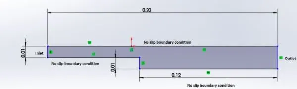
Let us divide above geometry into blocks as follow so that it makes task easy to create blockmesh.
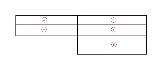
Assumptions:-
- Fluid is Newtonian fluid
- Fluid is incompressible
- Reynold number for flow is 2200
- Fluid is at 20 Degree celcius and at atm pressure.
As we know, `R_e=(rho*V*D)/mu`
where, `R_e` is Reynolds number
`rho` density of fluid in 'Kg/`m^3`'
`V` is velocity of fluid in 'm/s'
`D` is charecteristic length(diameter) in 'm'
`mu` is dynamic viscocity in 'N.s/`m^2`'
Consider fluid as a water,
Hence, above formula becomes-
`2200=(1000*V*0.01)/(1.002xx10^(-3))`
`V=0.22042" (m/s)"`
Boundary layer:
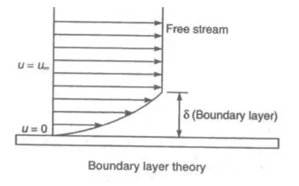
When fluid flow over a solid body, the velocity of fluid at boundary is zero. As we move away from boundary in perpendicular direction the velocity of fluid increases to free stream velocity. Thisis happens because when the fluid flows over object, the molecules right next to the surface stick to the surface due to viscocity. The molecules just above the surface are slowed down as collision happens with the previous layer's molecules. And similarly goes on with further layers as shown in above figure. And at some point the flow velocity reaches at free stream velocity.
Commands used during project:
- cd to change directory
- cd .. to return in previous directory.
- gedit to edit (text document) file.
- cp -r to copy whole directory.
- ls to show list of contents (files, directories) inside directory.
- run to open OpenFoam's run directory.
- cd $FOAM_TUTORIALS to open inbuilt OpenFoam's tutorial directory.
- blockMesh to start meshing.
- icoFoam to start simulation using icofoam solver.
- paraFoam to post-process data using paraview.
Simulation steps
- Open the Terminal in Ubuntu operating system.
- Type ‘cd $FOAM_TUTORIALS’ and it will take you into inbuilt tutorial directory of the OpenFoam software.
- By typing ‘cd incompressible’ go to the incompressible directory inside tutorials.
- Again type ‘cd icoFoam’ this will take you to icofoam directory.
- Again, change the directory to cavity by typing ‘cd cavity’.
- Now copy directory file of cavity to run directory by using ‘cp -r cavity/$FOAM_RUN’ command.
- Now type ‘run’ which will take you directly to run folder.
- Change the directory to system by using ‘cd cavity/system’ command. And type ‘ls’ to list out the files in system directory
- In ‘system-directory’ we can see four files i.e. blockMeshDict, controlDict, fvSchemes and fvSolution.
- Type ‘gedit blockMeshDict’ to edit the file, this file gives shape to our problem. We have to assume number to respective point for ease of shape creation.
- Similarly edit controlDict file by using ‘gedit controlDict’ command, this file controls our simulation by providing time limit, this file includes start time, end time, number of time intervals and Deltat.
- Always remember that the Courant number (CFL condition) should be less than 1 (CFL < 1) for stable solution, so choose Deltat & `nu` values accordingly.
- Return to the cavity directory by using command ‘cd ..’.
- To provide initial conditions change directory “0”. Edit the “P” and “U” files which are respectively includes initial pressure and initial velocity conditions. Edit these files by using ‘gedit’ command.
- Now return to cavity directory after editing all above files as per problem data.
- Type ‘blockMesh’ command and hit enter. Blockmesh command give us well structured mesh. If there has any error occurs while running file then check blockmeshDict file and try to create mesh again. If meshing done properly without error then type ‘icoFoam’ command to start solving simulation by using icoFoam solver.
- After completion of all above steps without error, let’s start for post processing by typing ‘paraFoam’ command.
OpenFoam has feature of grading factor (cell expansion) for each direction in the block. This function enables mesh creation to be graded or refined in specified direction. The ratio of the width of the last cell along one edge of a block to the width of the first cell along that same edge is called cell expansion ratio.
i.e. `"Grading factor"="Grading size of final cell"/"Grading size of first cell"`
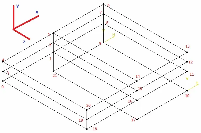
Above figure is used to define vertex of blocks in blockMeshDict file.
blockMeshDict file:
/*--------------------------------*- C++ -*----------------------------------*\
  =========                 |
  \\      /  F ield         | OpenFOAM: The Open Source CFD Toolbox
   \\    /   O peration     | Website:  https://openfoam.org
    \\  /    A nd           | Version:  8
     \\/     M anipulation  |
\*---------------------------------------------------------------------------*/
FoamFile
{
    version     2.0;
    format      ascii;
    class       dictionary;
    object      blockMeshDict;
}
// * * * * * * * * * * * * * * * * * * * * * * * * * * * * * * * * * * * * * //

convertToMeters 0.01;

vertices
(
    (0 0 0) //0
    (8 0 0) //1
    (8 0.5 0) //2
    (0 0.5 0) //3
    (0 1 0) //4
    (8 1 0) //5
    (20 1 0) //6
    (20 0.5 0) //7
    (20 0 0) //8
    (20 -1 0) //9
    (20 -1 0.1) //10
    (20 0 0.1) //11
    (20 0.5 0.1) //12
    (20 1 0.1) //13
    (8 1 0.1) //14
    (8 0.5 0.1) //15
    (8 0 0.1) //16
    (8 -1 0.1) //17
    (0 0 0.1) //18
    (0 0.5 0.1) //19
    (0 1 0.1) //20
    (8 -1 0) //21
);

blocks
(
    hex (0 1 2 3 18 16 15 19) (200 10 1) simpleGrading (1 1 1)
    hex (3 2 5 4 19 15 14 20) (200 10 1) simpleGrading (1 1 1)
    hex (2 7 6 5 15 12 13 14) (200 10 1) simpleGrading (1 1 1)
    hex (1 8 7 2 16 11 12 15) (200 10 1) simpleGrading (1 1 1)
    hex (21 9 8 1 17 10 11 16) (200 10 1) simpleGrading (1 1 1)
);
edges
(
);

boundary
(
    inlet
    {
        type patch;
        faces
        (
            (0 18 19 3)
            (3 19 20 4)
        );
    }

    outlet
    {
        type patch;
        faces
        (
            (12 7 6 13)
            (11 8 7 12)
            (10 9 8 11)
        );
    }

    front
    {
        type empty;
        faces
        (
            (1 0 3 2)
            (2 3 4 5)
            (7 2 5 6)
            (8 1 2 7)
            (9 21 1 8)
        );
    }

    back
    {
        type empty;
        faces
        (
            (18 16 15 19)
            (19 15 14 20)
            (15 12 13 14)
            (16 11 12 15)
            (17 10 11 16)
        );
    }

    top
    {
        type wall;
        faces
        (
            (4 20 14 5)
            (5 14 13 6)
        );
    }

    bottom
    {
        type wall;
        faces
        (
            (18 0 1 16)
            (17 21 9 10)
        );
    }

    step
    {
        type wall;
        faces
        (
            (21 17 16 1)
        );
    }
);

mergePatchPairs
(
);

// ************************************************************************* //
controlDict file:
/*--------------------------------*- C++ -*----------------------------------*\
  =========                 |
  \\      /  F ield         | OpenFOAM: The Open Source CFD Toolbox
   \\    /   O peration     | Website:  https://openfoam.org
    \\  /    A nd           | Version:  8
     \\/     M anipulation  |
\*---------------------------------------------------------------------------*/
FoamFile
{
    version     2.0;
    format      ascii;
    class       dictionary;
    location    "system";
    object      controlDict;
}
// * * * * * * * * * * * * * * * * * * * * * * * * * * * * * * * * * * * * * //

application     icoFoam;

startFrom       startTime;

startTime       0;

stopAt          endTime;

endTime         2.5;

deltaT          0.001;

writeControl    timeStep;

writeInterval   25;

purgeWrite      0;

writeFormat     ascii;

writePrecision  6;

writeCompression off;

timeFormat      general;

timePrecision   6;

runTimeModifiable true;


// ************************************************************************* //
Initial boundary condition of velocity:
/*--------------------------------*- C++ -*----------------------------------*\
  =========                 |
  \\      /  F ield         | OpenFOAM: The Open Source CFD Toolbox
   \\    /   O peration     | Website:  https://openfoam.org
    \\  /    A nd           | Version:  8
     \\/     M anipulation  |
\*---------------------------------------------------------------------------*/
FoamFile
{
    version     2.0;
    format      ascii;
    class       volVectorField;
    object      U;
}
// * * * * * * * * * * * * * * * * * * * * * * * * * * * * * * * * * * * * * //

dimensions      [0 1 -1 0 0 0 0];

internalField   uniform (0 0 0);

boundaryField
{
    inlet
    {
        type            fixedValue;
        value           uniform (0.22042 0 0);
    }

    outlet
    {
        type            zeroGradient;
    }

    front
    {
        type            empty;
    }

    back
    {
        type            empty;
    }

    top
    {
        type            noSlip;
    }

    bottom
    {
        type            noSlip;
    }

    step
    {
        type            noSlip;
    }
}

// ************************************************************************* //
Initial boundary condition of pressure:
/*--------------------------------*- C++ -*----------------------------------*\
  =========                 |
  \\      /  F ield         | OpenFOAM: The Open Source CFD Toolbox
   \\    /   O peration     | Website:  https://openfoam.org
    \\  /    A nd           | Version:  8
     \\/     M anipulation  |
\*---------------------------------------------------------------------------*/
FoamFile
{
    version     2.0;
    format      ascii;
    class       volScalarField;
    object      p;
}
// * * * * * * * * * * * * * * * * * * * * * * * * * * * * * * * * * * * * * //

dimensions      [0 2 -2 0 0 0 0];

internalField   uniform 0;

boundaryField
{
    inlet
    {
        type            zeroGradient;
    }

    outlet
    {
        type            fixedValue;
        value           uniform 0;
    }

    front
    {
        type            empty;
    }

    back
    {
        type            empty;
    }

    top
    {
        type            zeroGradient;
    }

    bottom
    {
        type            zeroGradient;
    }

    step
    {
        type            zeroGradient;
    }
}

// ************************************************************************* //
Velocity flow animation:
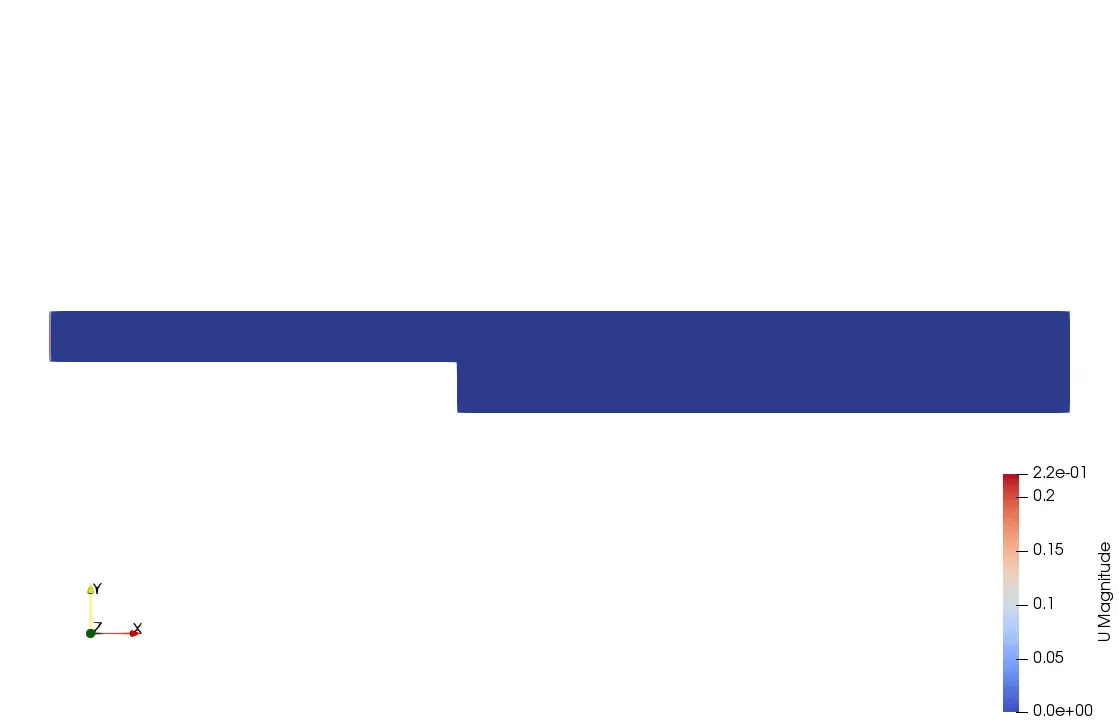
Animation shows velocity flow of fluid over backward facing step. Above animation simply shows how vortex is created at step.
Condition for kinematic viscocity:
/*--------------------------------*- C++ -*----------------------------------*\
  =========                 |
  \\      /  F ield         | OpenFOAM: The Open Source CFD Toolbox
   \\    /   O peration     | Website:  https://openfoam.org
    \\  /    A nd           | Version:  8
     \\/     M anipulation  |
\*---------------------------------------------------------------------------*/
FoamFile
{
    version     2.0;
    format      ascii;
    class       dictionary;
    location    "constant";
    object      transportProperties;
}
// * * * * * * * * * * * * * * * * * * * * * * * * * * * * * * * * * * * * * //

nu              [0 2 -1 0 0 0 0] 1.004e-6;


// ************************************************************************* //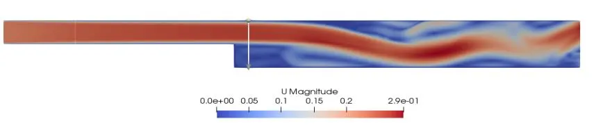
Above figure shows flow of velocity at grading factor of 1.
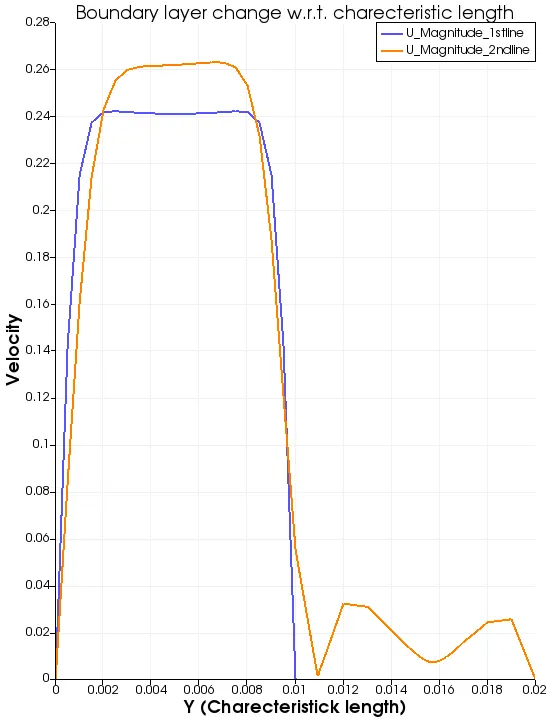
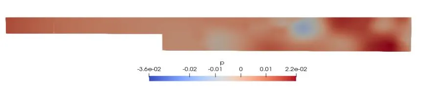
Above graph plotted is velocity v/s Characteristics length along Y-axis. It also shows that how baundary layer seperation happens along characteristic length. Line 1 is drawn at X=0.025m and line 2 is drawn at 0.085m to obtained above plot. This plot is obtained for flow at grading factor 1.
Block defination for 0.2 grading factor:
blocks
(
    hex (0 1 2 3 18 16 15 19) (200 10 1) simpleGrading (0.2 1.2 1)
    hex (3 2 5 4 19 15 14 20) (200 10 1) simpleGrading (0.2 0.2 1)
    hex (2 7 6 5 15 12 13 14) (200 10 1) simpleGrading (1.2 0.2 1)
    hex (1 8 7 2 16 11 12 15) (200 10 1) simpleGrading (1.2 1 1)
    hex (21 9 8 1 17 10 11 16) (200 10 1) simpleGrading (1.2 1.2 1)
);
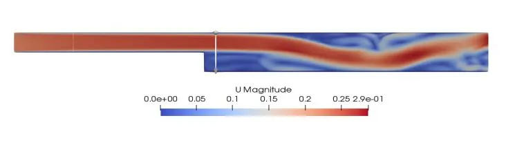
Above figure shows flow of velocity at grading factor of 0.2.
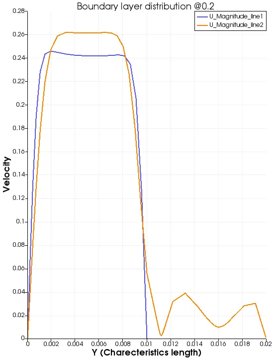
Above graph plotted is velocity v/s Characteristics length along Y-axis. It also shows that how baundary layer seperation happens along characteristic length. Line 1 is drawn at X=0.025m and line 2 is drawn at 0.085m to obtained above plot. This plot is obtained for flow at grading factor 0.2.
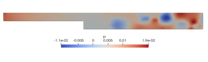
Block defination for 0.5 grading factor:
blocks
(
    hex (0 1 2 3 18 16 15 19) (200 10 1) simpleGrading (0.5 1.5 1)
    hex (3 2 5 4 19 15 14 20) (200 10 1) simpleGrading (0.5 0.5 1)
    hex (2 7 6 5 15 12 13 14) (200 10 1) simpleGrading (1.5 0.5 1)
    hex (1 8 7 2 16 11 12 15) (200 10 1) simpleGrading (1.5 1.5 1)
    hex (21 9 8 1 17 10 11 16) (200 10 1) simpleGrading (1.5 1.5 1)
);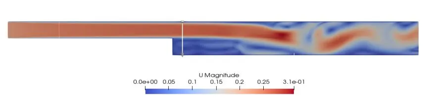
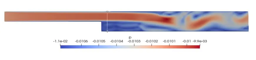
Above figure shows flow of velocity at grading factor of 0.5.
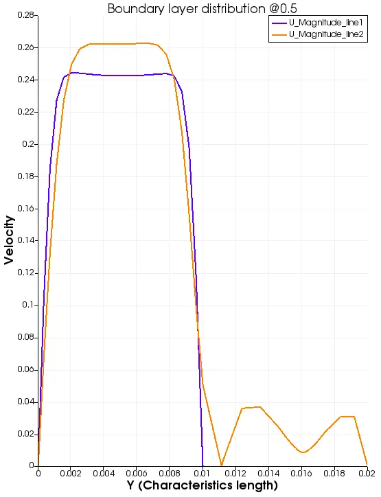
Above graph plotted is velocity v/s Characteristics length along Y-axis. It also shows that how baundary layer seperation happens along characteristic length. Line 1 is drawn at X=0.025m and line 2 is drawn at 0.085m to obtained above plot. This plot is obtained for flow at grading factor 0.5.
Block defination for 0.8 grading factor:
blocks
(
    hex (0 1 2 3 18 16 15 19) (200 10 1) simpleGrading (0.8 1.8 1)
    hex (3 2 5 4 19 15 14 20) (200 10 1) simpleGrading (0.8 0.8 1)
    hex (2 7 6 5 15 12 13 14) (200 10 1) simpleGrading (1.8 0.8 1)
    hex (1 8 7 2 16 11 12 15) (200 10 1) simpleGrading (1.8 1.8 1)
    hex (21 9 8 1 17 10 11 16) (200 10 1) simpleGrading (1.8 1.8 1)
);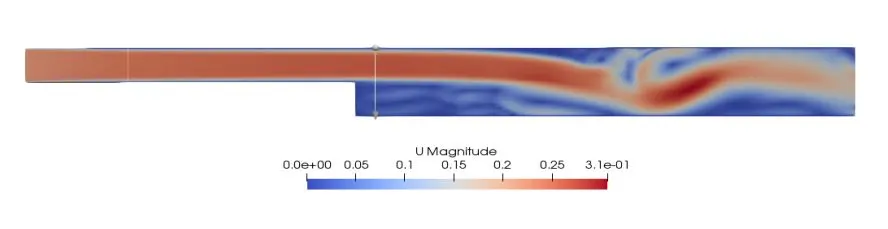
Above figure shows flow of velocity at grading factor of 0.8.
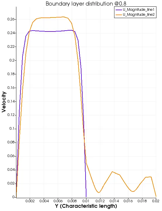
Above graph plotted is velocity v/s Characteristics length along Y-axis. It also shows that how baundary layer seperation happens along characteristic length. Line 1 is drawn at X=0.025m and line 2 is drawn at 0.085m to obtained above plot. This plot is obtained for flow at grading factor 0.8.
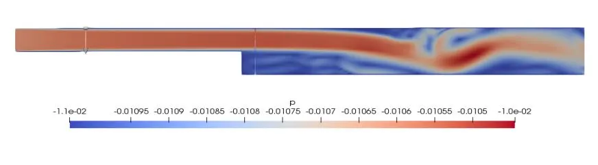
Conclusion:-
Above velocity plots obtained for every grading factor are nearely similar, but if studied deeply it is seen that for lower grading factor at walls the solution is more accurate.
For lower values of grading factor at the walls the fluid attains free stream velocity more quickly.