week-11 Joint creation and Demonstration
Objective:
Using the manual (*CONSTRAINED_JOINT keyword) demonstrate spherical, revolute, cylindrical, and translational joints between two rigid bodies and two deformable bodies.
To understand the process, follow the guidelines below:
A joint is created using an even number of nodes, out of which every pair has the same position (XYZ coordinate). These nodes should belong to the bodies between which the joint operates.
So, for example, for a revolute joint, we will have four nodes and their coordinates can be
NID X Y Z
1 100 120 350
2 100 120 350
3 100 150 350
4 100 150 350
Nodes (1, 3) belong to body1 and (2,4) belong to body2. Since the line from node 1 to 3 or node 2 to 4 is the axis of rotation.
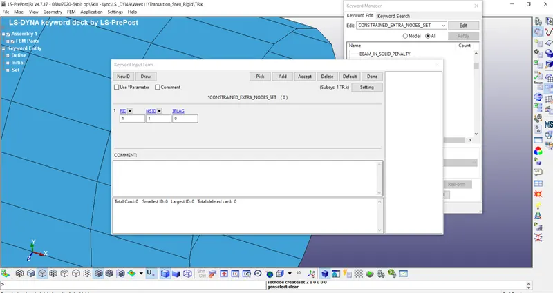
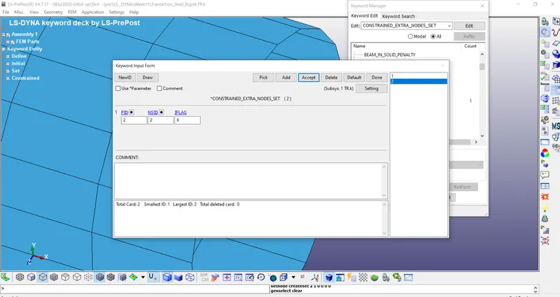
We use *CONSTRAINED_EXTRA_NODES and *CONSTRAINED_NODAL_RIGID_BODY to create joints between rigid and deformable bodies respectively.
Rigid Body: Once you create the nodes at the required location, use *CONSTRAINED_EXTRA_NODES to include those nodes to the respective rigid bodies.
Deformable Body: The nodes should be part of a *CONSTRAINED_NODAL_RIGID_BODY which has some shared nodes with the deformable body.
An illustration is shown below on how to demonstrate the joints. However, more creative efforts to show linkages, etc. are welcome. To demonstrate the joints' working, rotation and translatory motions should be shown. The final submission should include input files for each of the joints and animations showing their results. This assignment tests a student's ability to go through the manual, understand the topic, and apply it to their model since this topic is not extensively covered in the course.
Procedure:
- Spherical Joint – Rigid
Create the Sphere and hemisphere using shape mesher of sphere shell – Parts (hemisphere & sphere)
Assign Mat (Rigid) & Sec Shell for the parts accordingly

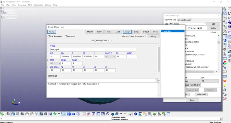
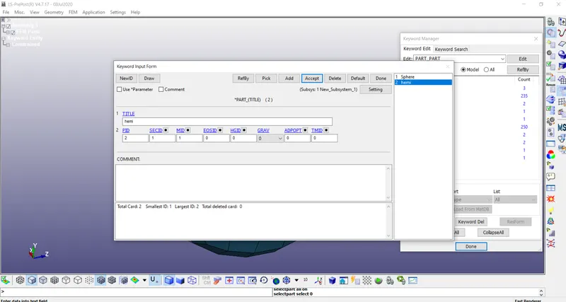
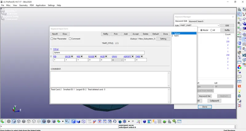
Create two nodes at the center of the sphere at the same location. Assign the nodes to each part
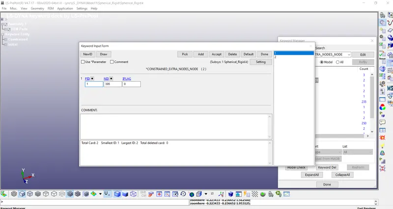
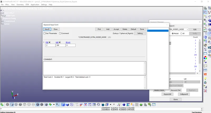
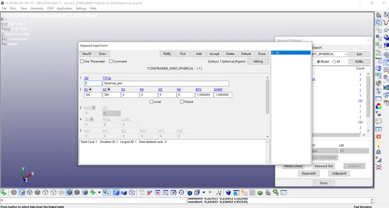
Create a Spherical joint and add the two nodes.
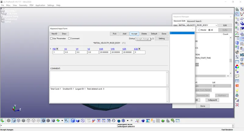
Create Initial Velocity to the inner sphere
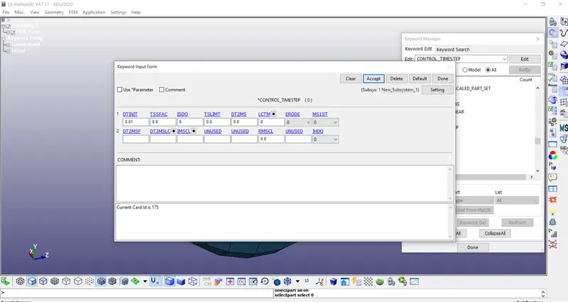
Add Control time cards – common for all joints
Control Timestep
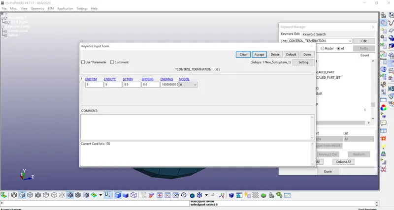
Control Termination
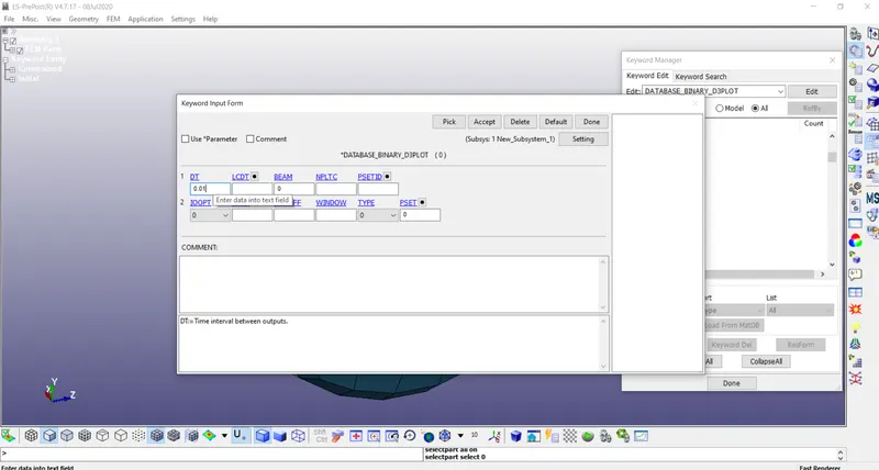
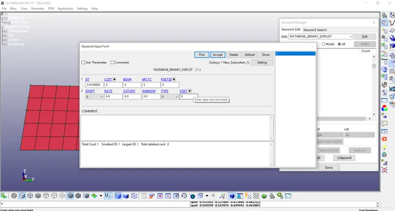
Database Binary D3 plot
Save the file and run it in LS run
- Spherical Joint – Deform – Do changes from the Rigid as follows
Assign Mat (Elastic) & Sec Shell for the parts accordingly
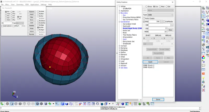
Create the CNRB for both the parts to the node.
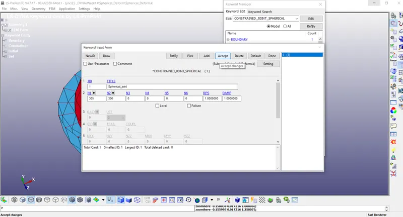
Create a Spherical joint and add the two nodes.
Assign Velocity to the inner sphere
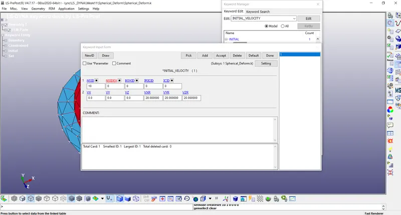
Save the file and run it in LS run
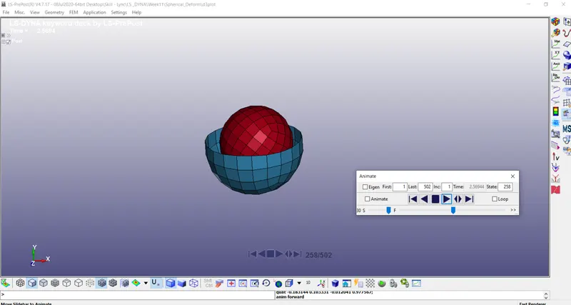
3. Revolute Joint – Rigid
Create two rectangles using Shape Mesher of 4N shell – Parts (Part1 & Part2)
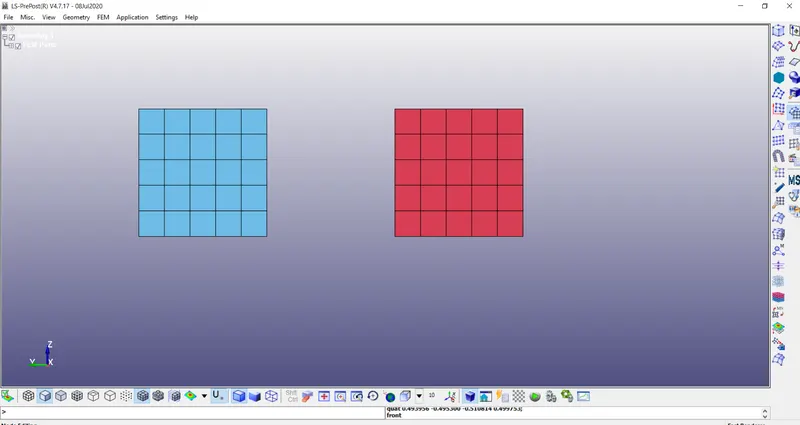
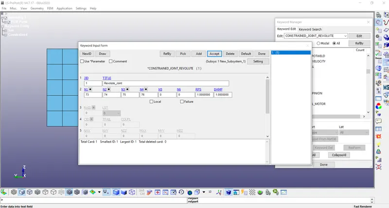
Create four nodes 73 74 75 76 at two places coincident 73 & 74, 75 & 76 – one set to part A 73&75, one set to part B 74&76
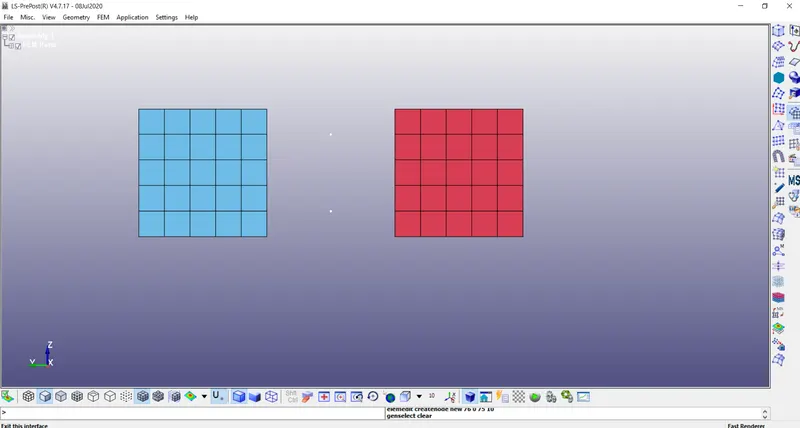
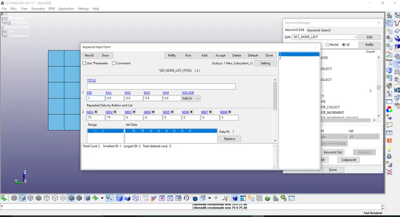
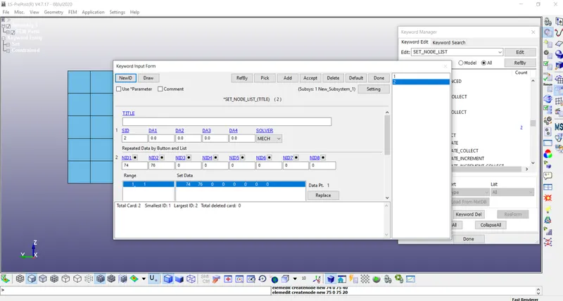
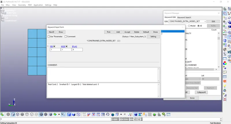
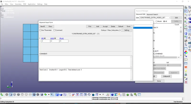
Assign Mat (Rigid) & Sec Shell for the parts accordingly
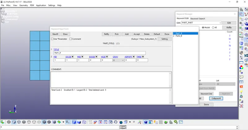
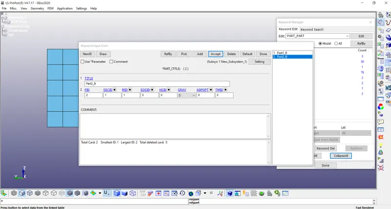
Create a Revolute joint and add the four nodes.
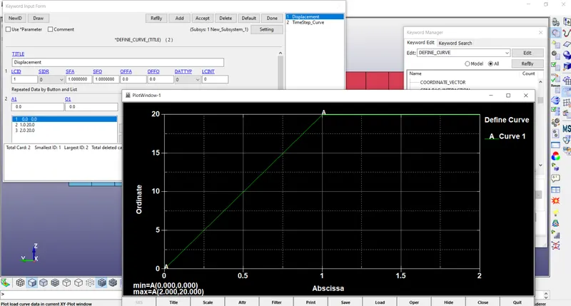
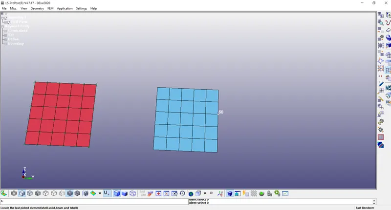
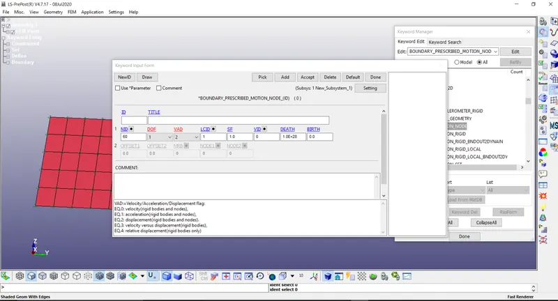
Create an Initial Displacement curve and assign to one of the nodes to Part 2
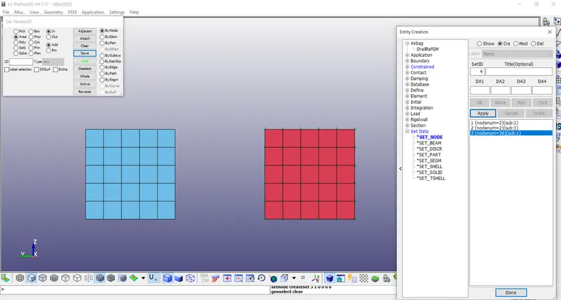
Constraint all the nodes of Part 1
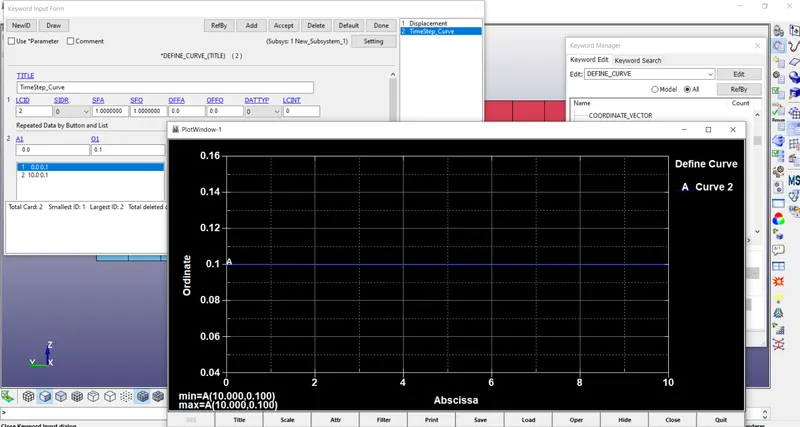
Create a time step curve and assign it to control timestep
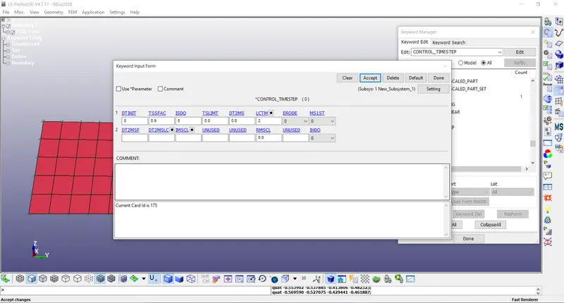
Add Control time cards and database d3 plot– common for all joints
Save the file and run it in LS run
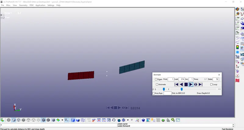
- Revolute Joint – Deform – Do changes from the Rigid as follows
Assign Mat (Elastic) & Sec Shell for the parts accordingly
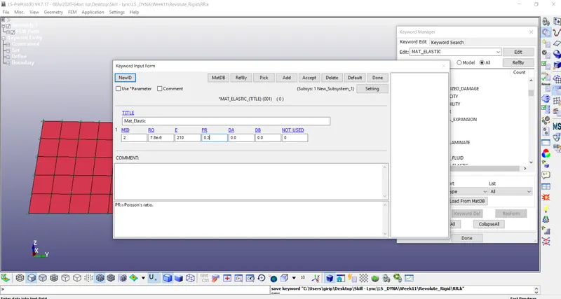
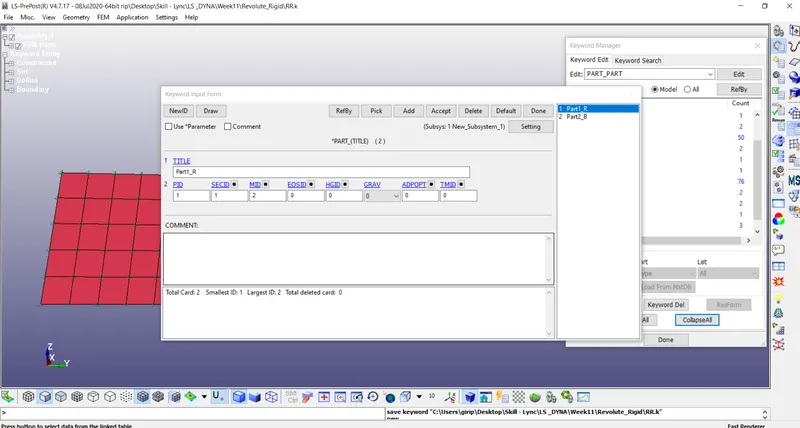
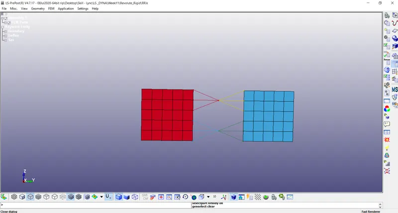
Create the CNRB for both the parts to the nodes.
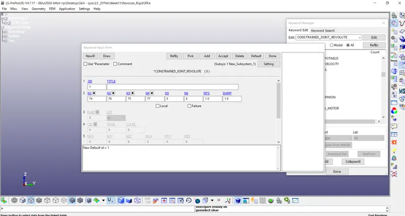
Create a Revolute joint and add the four nodes.
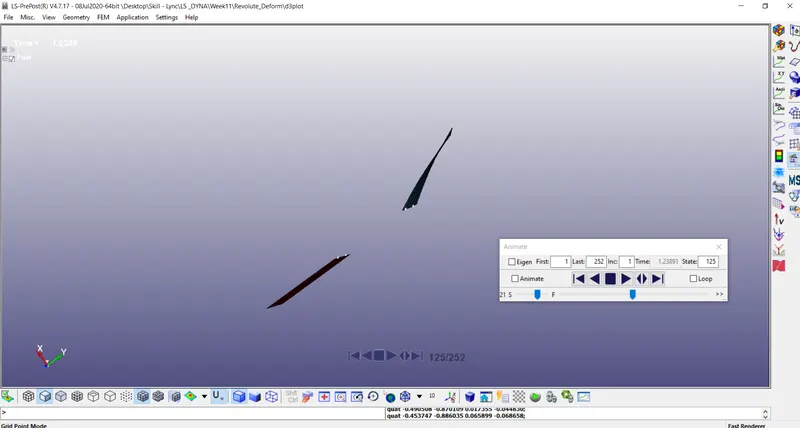
Save the file and run it in LS run
- Translation Joint – Rigid
Create two box shells using Shape Mesher of Box shell – Parts (Part1 & Part2)
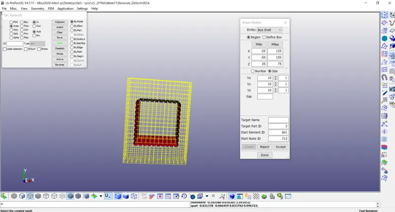
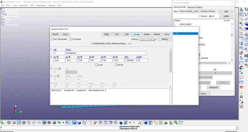
Create six nodes 1744 1745 1746 1747 1748 1749 at three places coincident (two collinear and third one middle away from the two) 1744 &1745 1746 &1747 1748& 1749 – three set to part A 1744 1746 1748, one set to part B 1745 1747 1749
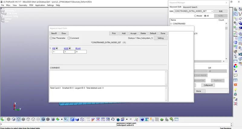
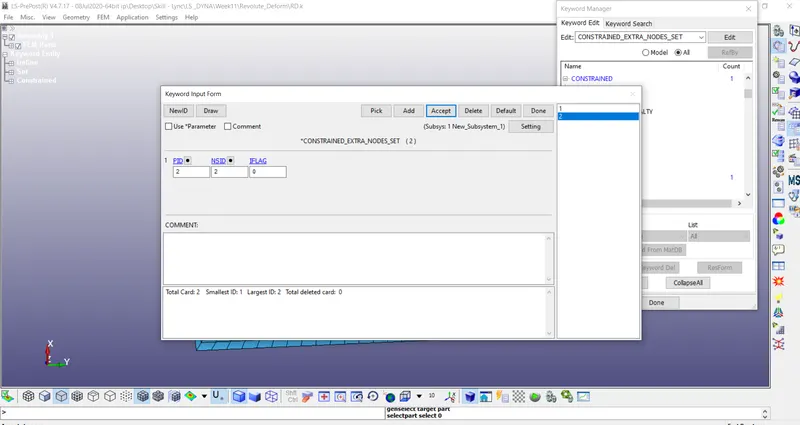
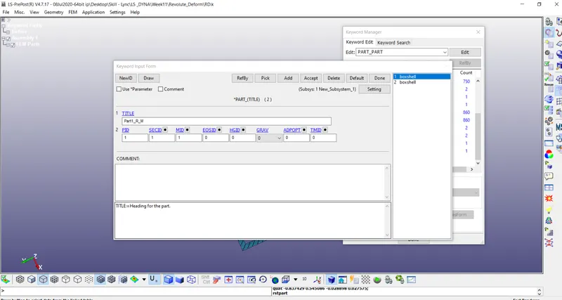
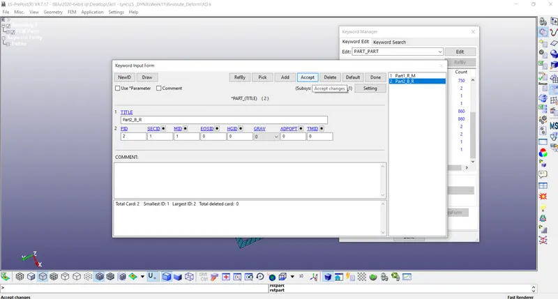
Assign Mat (Rigid) & Sec Shell for the parts accordingly
Create a Translate joint and add the six nodes.
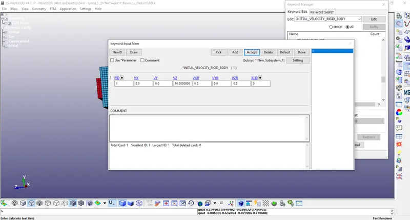
Create Initial Velocity Rigid to the inner box shell
Constraint all the nodes of the outer box shell
Add Control time cards and database d3 plot– common for all joints
Save the file and run it in LS run
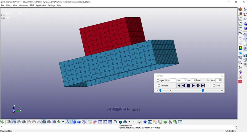
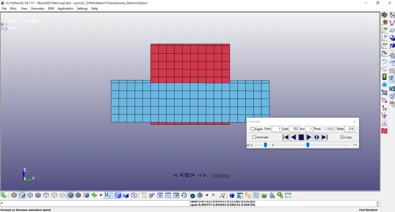
- Translate Joint – Deform – Do changes from the Rigid as follows
Assign Mat (Elastic) & Sec Shell for the parts accordingly
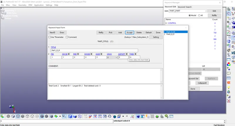
Create the CNRB for both the parts to the nodes.
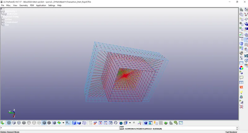
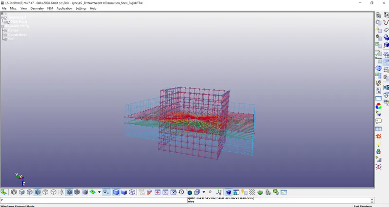
Create a Translate joint and add the six nodes.
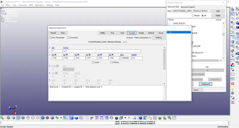
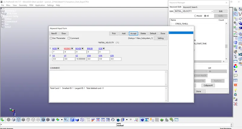
Create Initial Velocity to the inner box shell – creating node-set
Save the file and run it in LS run
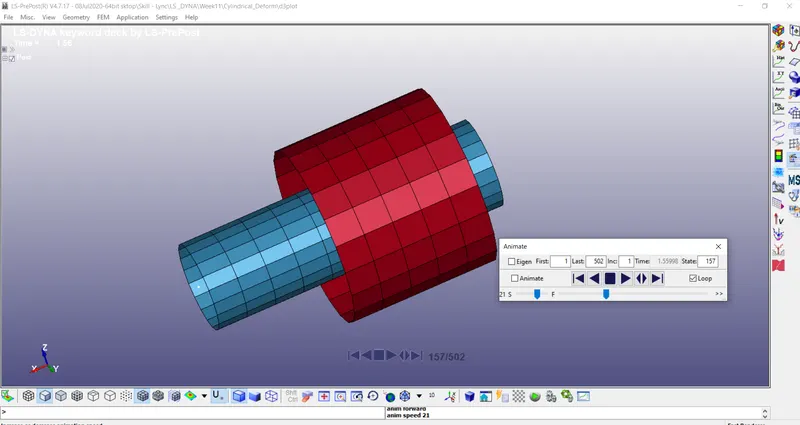
- Cylindrical Joint – Rigid
Create two-cylinder shells using Shape Mesher of cylinder shell – Parts (Part1 & Part2)
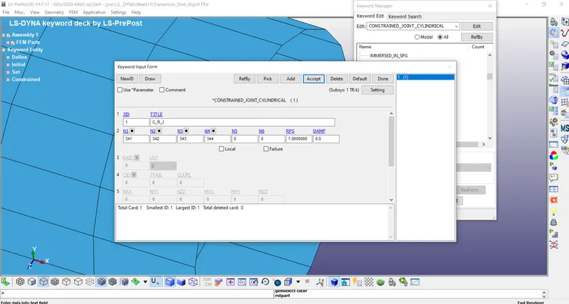
Create four nodes 341 342 343 344 at two places coincident 341&342 343&344 – one set to part A 341 & 343, one set to part B 342&344
Assign Mat (Rigid) & Sec Shell for the parts accordingly
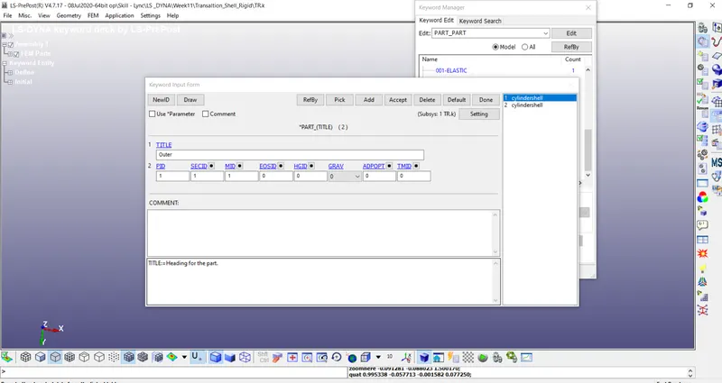
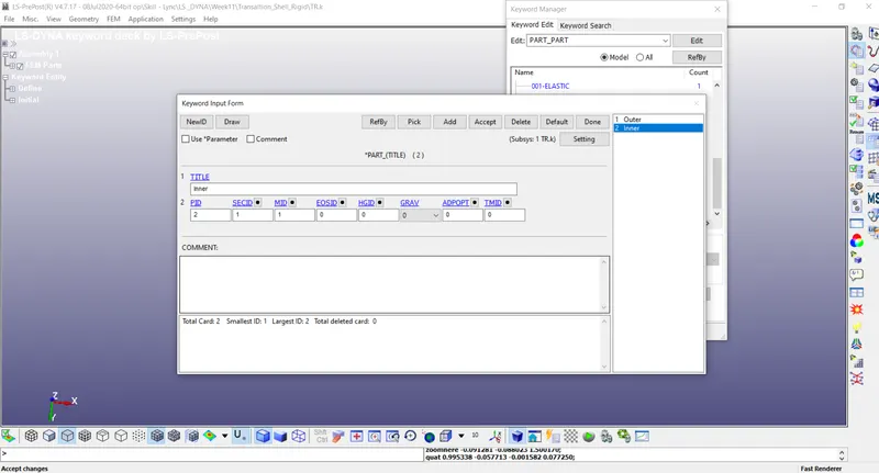
Create a Cylindrical joint and add the four nodes.
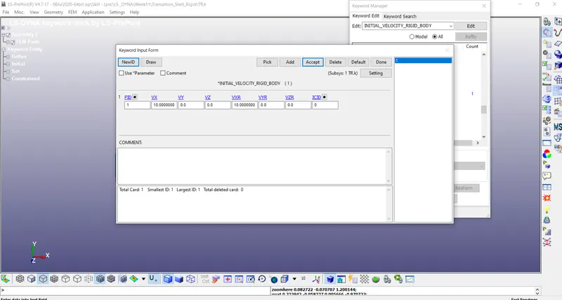
Create Initial Velocity Rigid to the inner cylinder shell
Constraint all the nodes of the outer cylinder shell
Add Control time cards and database d3 plot– common for all joints
Save the file and run it in LS run
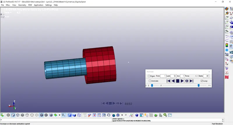
- Cylindrical Joint – Deform – Do changes from the Rigid as follows
Assign Mat (Elastic) & Sec Shell for the parts accordingly
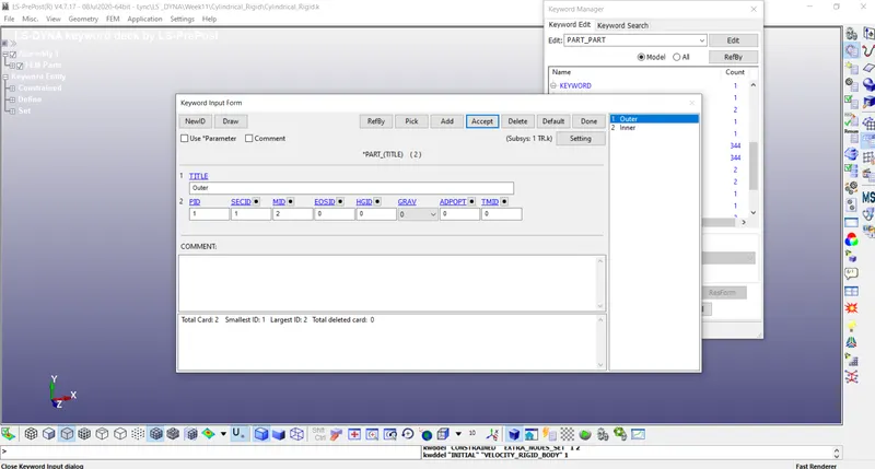
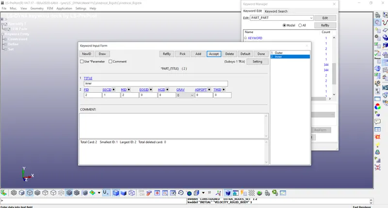
Create the CNRB for both the parts to the nodes.
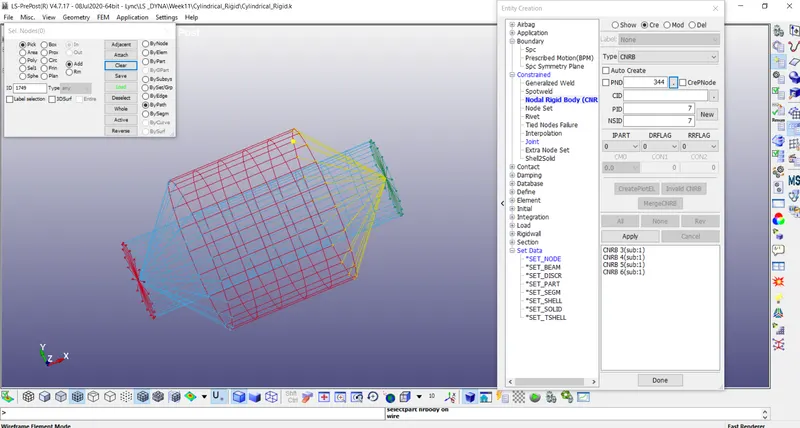
Create a Cylindrical joint and add the four nodes.
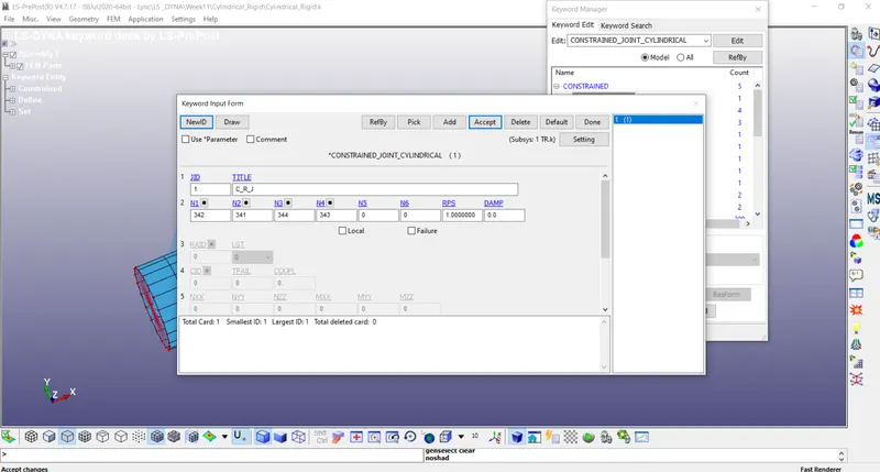
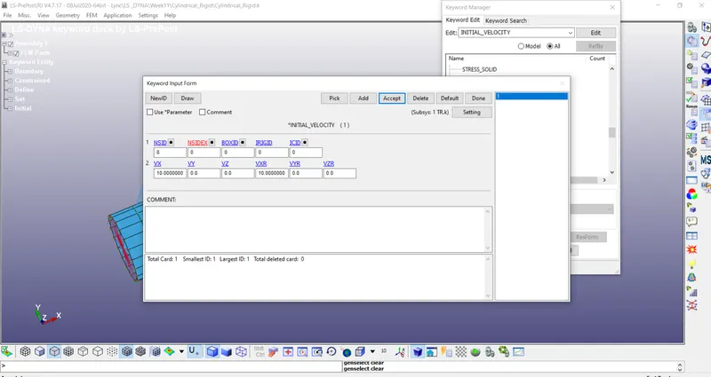
Create Initial Velocity to the inner cylinder shell – creating node-set
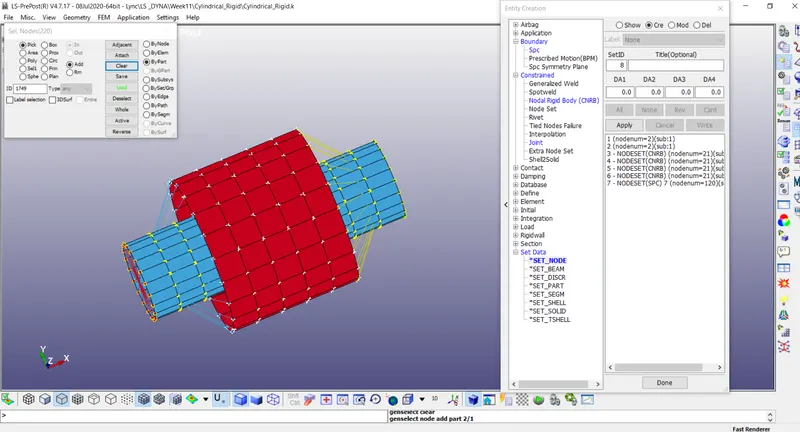
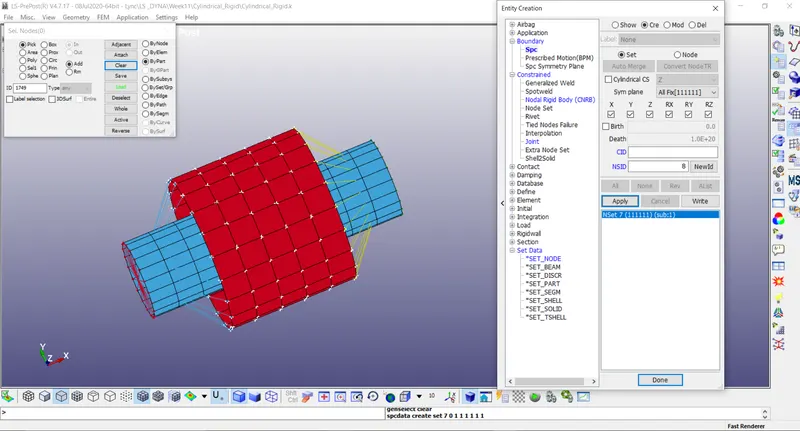
Constraint all the nodes of the outer cylinder shell
Save the file and run it in LS run
Conclusion
All the joints are created and simulated in LS Dyna