Joint creation using Ls-Dyna
OBJECTIVE
- To build different joint like spherical, revolute, translational and cylindrical in Ls-Dyna.
- Explore Extra nodes for rigid bodies and constrained nodal rigid body for deformable bodies to build these joints.
- Build geometry suitable for each joint type.
THEORY
- Different joints can be built in Ls-Dyna using extra nodes and constrained nodal rigid body.
- Each joints require the rigid body nodes to create the joints
- Extra nodes are required to build joints for rigid bodies whereas for deformable bodies we require to get a constrained nodal rigid body for these joints.
- Spherical joints have only rotational degrees of freedom (DOF) whereas translational motion is constrained. These joints require only one pair of common nodes for joint creation.
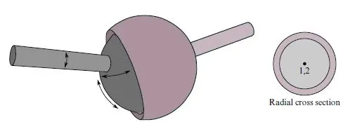
- Revolute joints: Formed of pair of two sets of coinciding nodes in between. The rotational motion is only allowed along the axis formed by two pair of coinciding nodes.
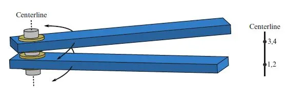
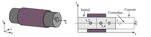
- Cylindrical Joints: Formed of two sets of coinciding nodes on the centre axis of 2 bodies. This joint is derived from the rotational joint by relaxing the constraints along the centreline. This joint admits relative rotation and translation along the centreline.
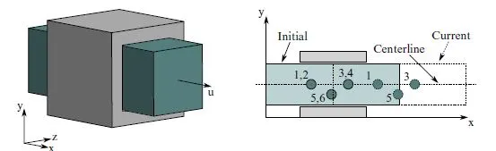
- Translational Joints: Formed of 3 sets of coinciding nodes. This is a cylindrical joint with a third pair of off centreline nodes which restrict rotation. Aside from translation along the centreline, the two rigid bodies are stuck together
PROCEDURE
- For all different cases there are few common keyword used like Control_Termination, Control_timestep, Database binary_D3plot.
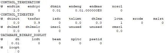
- Also the geometry is created using Mesh->Shape mesher option unless specified otherwise.
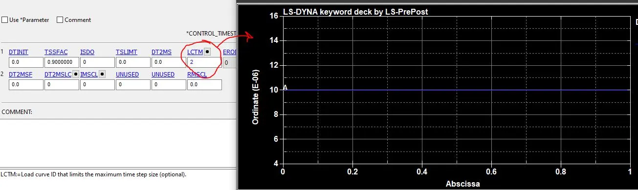
NOTE: Since the geometries in the exercise is self created, the mesh size being large there may be some instability in the simulation due to larger time step generated by the solver. So in order to overcome that, smaller time step of the order of 1e-5 or smaller is defined using lctm option in control_timestep card.
Method 1: Using Extra Nodes
The material formulation in each cases remains same and is explained in detail in Spherical joint.
Spherical Joint
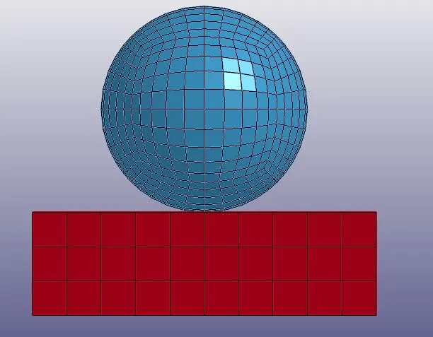
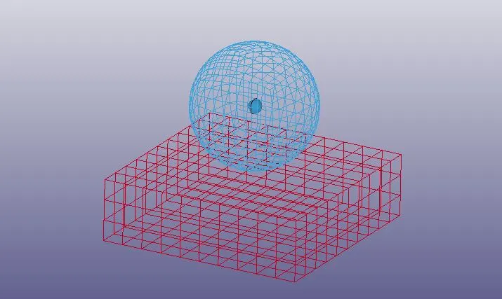
- One of the basic example to understand the spherical joint is the plate and sphere specimen as shown in the figure below. This is built using box solid and solid sphere option in shape mesher.
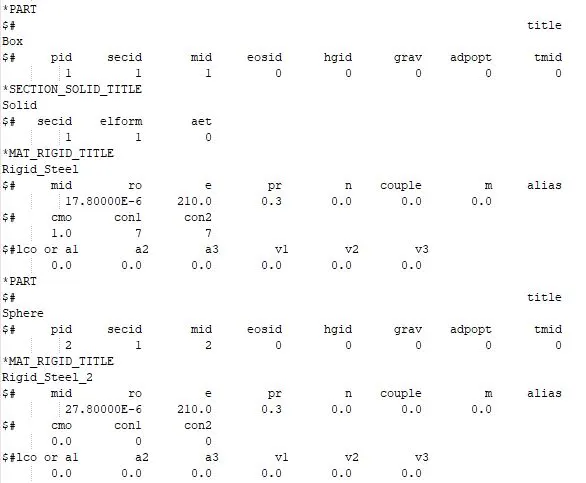
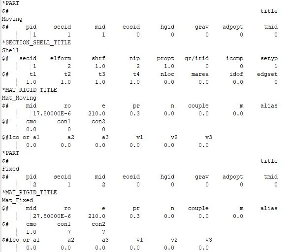
- Both plate and Sphere are rigid bodies. Section is selected and MAT20 Rigid body material card is called. In material card there are two option CON1 and CON2 which dictates the movements of the parts. Both translational and rotational movements can be controlled using these two option. Restrict all the movement for base plate and keep movements free for the sphere.
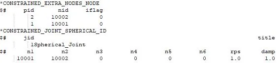
- After geometry, construct two coinciding nodes. Assign them to their respective rigid bodies using Constrained_Extra_Nodes
- Now create a spherical joint using Constrained_joint_Spherical and enter the node no. of extra nodes.
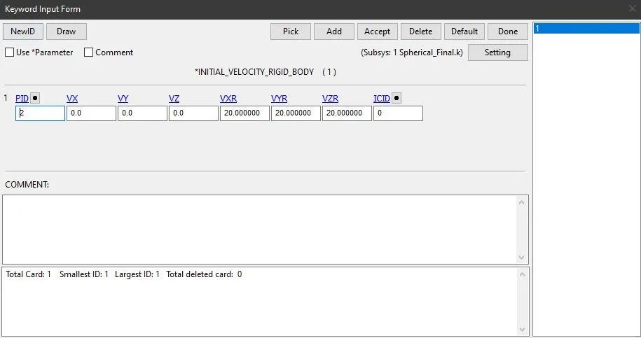
- The motion is assigned using initial_velocity_RigidBody card as shown below.
- The working spherical joint can be seen below.

Revolute joint
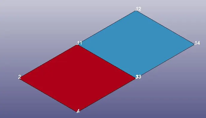
- Two different coplanar 4N shells are constructed with node 1-2-3-4 and 11-12-13-14. Here coincident node pair is 1-11 and 3-13. Alternatively if the node of the body are not coincident, then additional pair of nodes can be constructed and the procedure discussed above can be followed
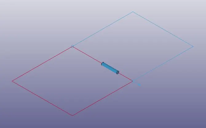
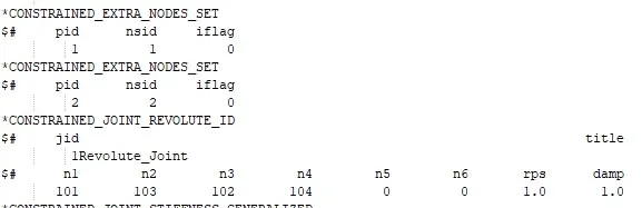
- Create a revolute joint using Constrained_Joint_Revolute and enter the node no. Here NSID 1 = node 101 and 102, NSID2 = node 103 and 104. These are assigned to rigid bodies using extra nodes card
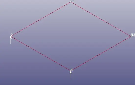
- Motion assigned is in the form of load point on node 2 and 4 using Load_Node_Point The load curve is as follows

Working Revolute Joint is as follows
Cylindrical Joint
- Two concentric hollow cylindrical shells are constructed using curve and extrude options and meshed using auto mesher. Outer one is fixed and inner one is moving
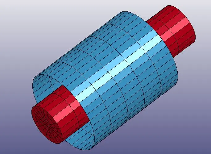
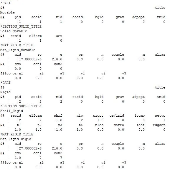
- We require two coincident node pairs along the centre axis of the body. This can be done using extra nodes card. NSID 1 = nodes 10001 and 10002, NSID 2 = 10003 and 10004.
- Create cylindrical joint using Constrained_Joint_Cylindrical and enter the node no.
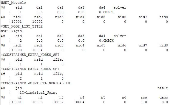
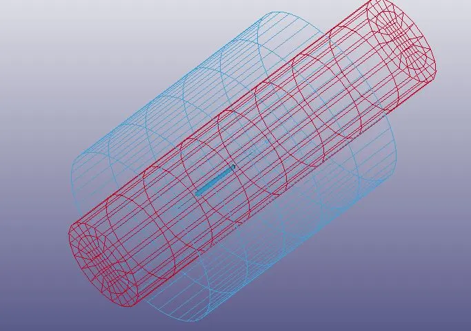
- The motion here is assigned using initial_velocity_rigidbody

Working Cylindrical joint

Translational Joint
- Translational Joint follows the same procedure as cylindrical joint with additional pair of coincident nodes to restrict rotation. The geometry is created using curve and extrude options and meshed using auto mesher.
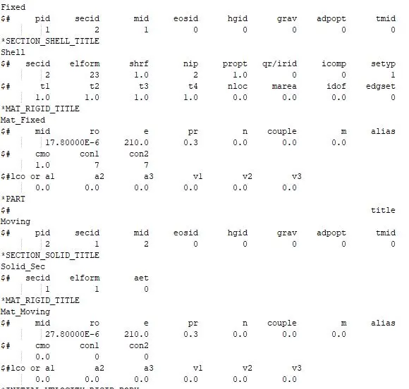
- Constrained_Joint_Translational is used to create this type of joint. Here NSID 1 = nodes 50001, 50002 and 50003, NSID 2 = 50004, 50005, 50006. Extra nodes card is used to assign these nodes to their rigid body.
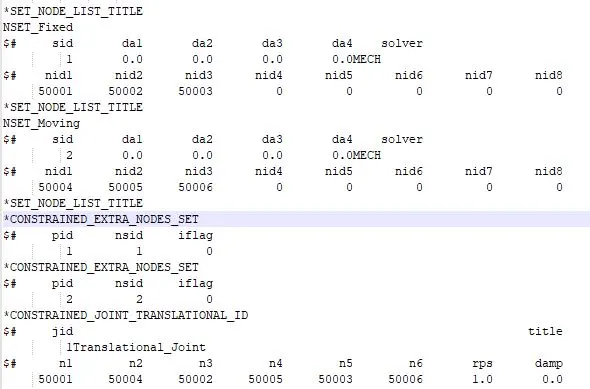
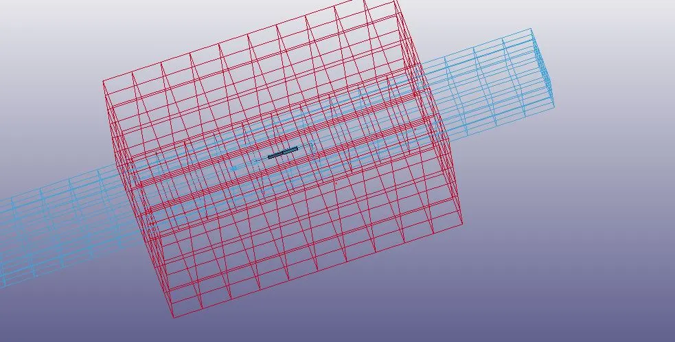
- The motion here is assigned using initial_velocity_rigidbody
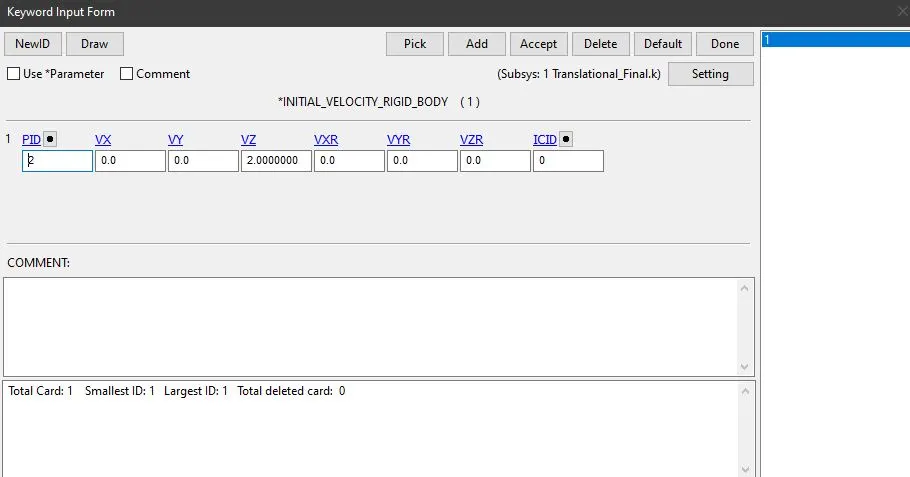
Working Translational Joint
METHOD 2: Using Constrained Nodal Rigid bodies (CNRB)
- The procedure of making joints remain exactly the same. The difference is the there is no need of extra nodes, instead we create coinciding CNRB using the nodes of existing deformable body.
- The material for the bodies is taken as elastic using MAT01 card.
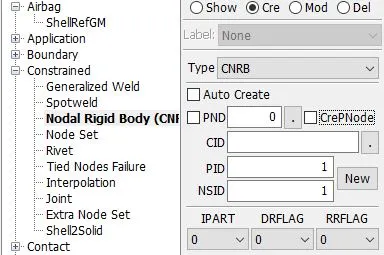
- To construct CNRB, go to create entity-> constrained-> nodal rigid body (CNRB) -> select the nodes on deformable bodies -> create (this creates a master node for CNRB). Now there are two options for master node i.e. PND and CrePnode as shown below. PND allows us to assign on of the existing nodes as a master node whereas CrePNode creates an additional node in the centre of the selected node.
- Also the allowable motion of CNRB can be controlled using RRFLAG and DRFLAG card.
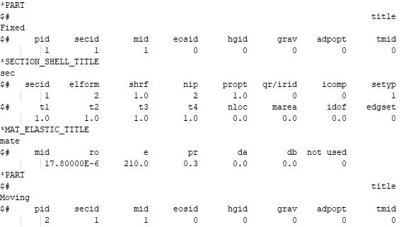
- All the joints follow the same procedure for material, section and part and is discussed in detail in spherical joints
Spherical Joint
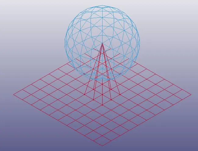
- This is built using box shell and shell sphere option in shape mesher. Both plate and Sphere are deformable elastic bodies. Shell Section is selected and MAT01 elastic material card is called.
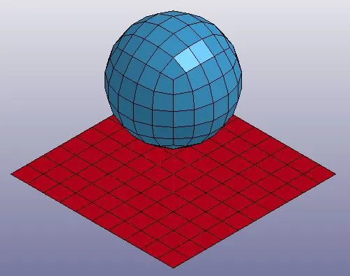
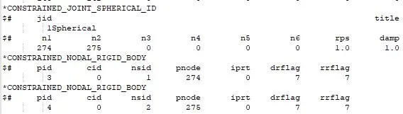
- Now create two coincident CNRB for each part. Creat a spherical joint using Constrained_joint_Spherical and enter the node no. of coincident master nodes (274-275).
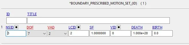
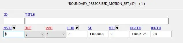
- The motion is assigned to sets of nodes of the sphere in the form of prescribed boundary motion set.
Working SPherical Joint
Revolute Joint
- Two different coplanar 4N shells are constructed using Shape mesher option.
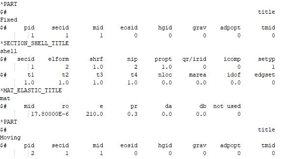
- Now create two pair of coincident CNRB using create entity option. Create revolute joint using Constrained_joint_Revolute and enter the node no. of coincident master nodes. (137-138, 139-140).
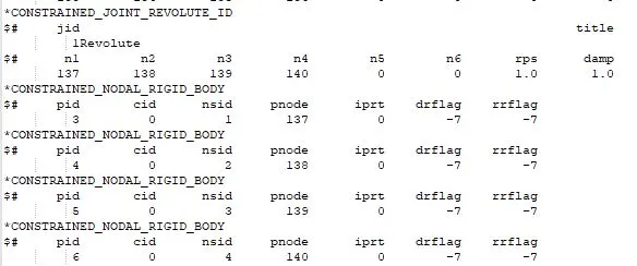
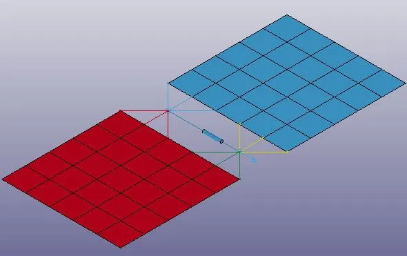
- The motion is assigned to sets of nodes on outer edge of the moving shell in the form of prescribed boundary motion set.
Working Revolute Joint
Cylindrical Joint
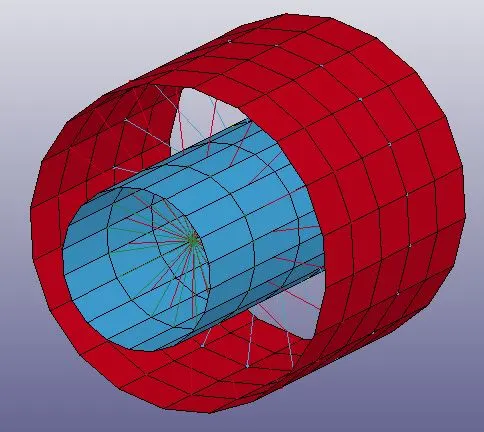
- Two concentric hollow cylindrical shells are constructed using curve and extrude options and meshed using auto mesher. Outer one is fixed and inner one is moving.
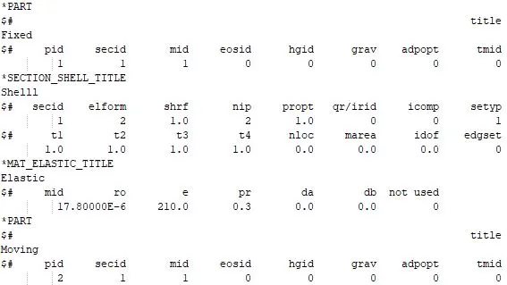
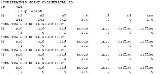
- Create two CNRB on inner and outer cylinder each using all the nodes in circumferential direction. The master nodes must lie on the centre axis of the cylinders. Create cylindrical joint using Constrained_Joint_Cylindrical using these pair of coincident master nodes(241-243, 242-244).
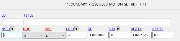
- The motion is assigned to sets of nodes of the moving shell in the form of prescribed boundary motion set
Working Cylindrical Joint
Translational Joint
- Translational Joint follows the same procedure as cylindrical joint with additional pair of coincident nodes to restrict rotation. The geometry is created using curve and extrude options and meshed using auto mesher.
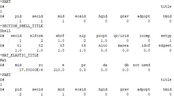
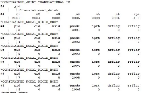
- Create three CNRB on inner and outer shell each using all the nodes in circumferential direction. The master nodes must lie on the centre axis of the cylinders. Create cylindrical joint using Constrained_Joint_Translational using these pair of coincident master nodes (2001-2004, 2002-2005, 2003-2006).
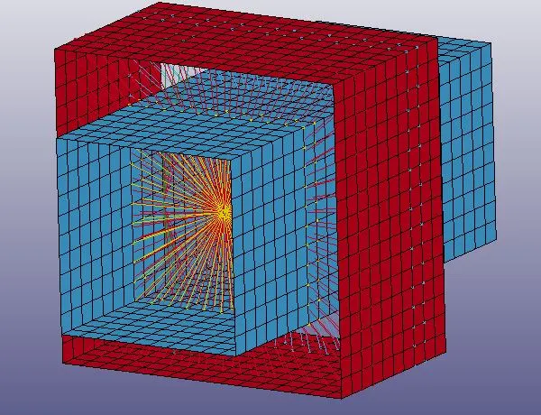
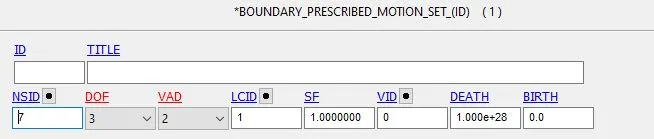
- The motion is assigned to sets of nodes of the moving shell in the form of prescribed boundary motion set
Working Translational joint
CONCLUSION
The above exercise helps us understand the procedure of creating 4 different types of joint for both rigid bodies and deformable bodies using Constrained_Extra_Nodes and CNRBs respectively. Other types of joints can also be explored using the method of extra nodes and CNRB
Link:
https://drive.google.com/drive/folders/1AJsFgxvIz2ue1qv17ji1KnFClqPnGCpR?usp=sharing