week-11 Joint creation and Demonstration
Aim: To Create Cylindrical,Translational,Revolute & Spherical Joints between two rigid and deformable bodies using LS dyna solver
Procedure:
- Here we need to create four joints ie Translational,Revolute,Cylindrical and Spherical joints
- The joints are to be created between two rigid bodies and two deformable bodies seperately ie the case here
Common cards for set up
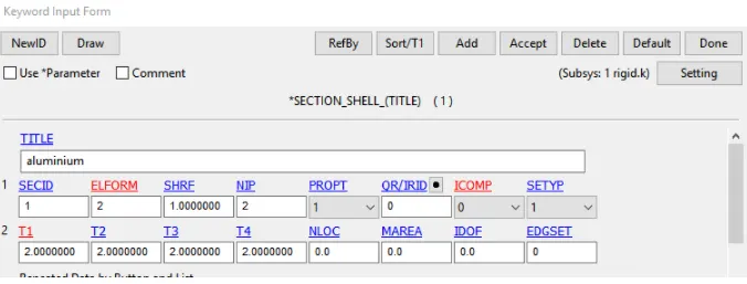
The section card with elform 2 and thickness 2mm was used throughout all the cases
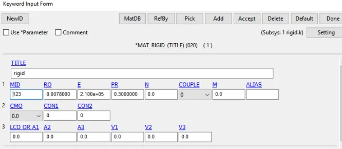
The mat 20 Was used for rigid cases
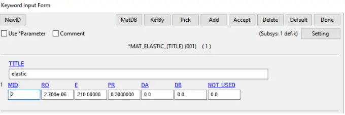
The Mat_01 was used for deformable cases
Control Card
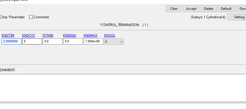
The termination card with 2.0 ms was used for the 4 cases
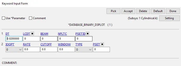
The database binary D3 plot with 0.02 ms time step was used for all cases
Procedure:
Revolute Joint
Case1:Rigids
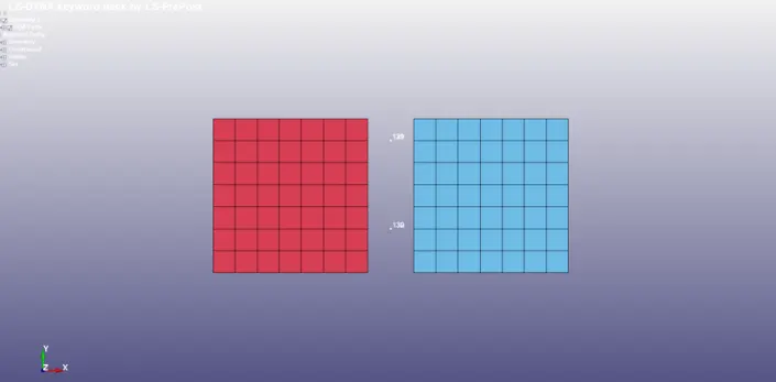
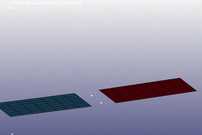
1.The two four noded shells is created using mesh option with 2 part ID's
2. Four noded shells with 2 pair of co incident nodes were created at the centre between two shell element parts is created
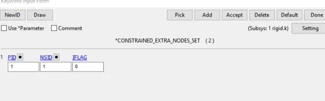
3.The nodes created between two parts were asssigned to part's using Constrained extra node set keyword
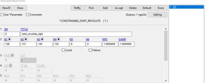
4.The Constrained Joint Revolute was created using the Extra nodes
5.After this velocity rigid was assigned to part 2 and Part 1 was fixed using SPC
Case 2:Deformable
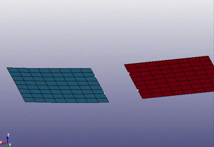
For deformable case we need to create CNRN in place of Extra nodes set
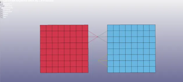
In this case the MAt card was changed from Rigid to elastic
Also the velocity card was cahnged from rigid to Initial as we are not using any rigid here
Spherical Joints
Case1:rigid
1.Two Spherical Shells is created using Mesh option with two part ID's
2.Two nodes are created at the centre of the shpere coinciding each other
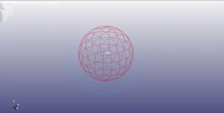
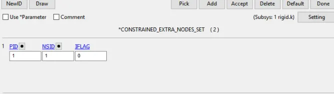
3.To assigning the nodes to their part we first need to create Node sets for the extra Nodes and then after they are assigned to Part using Constrained Extra Nodes set
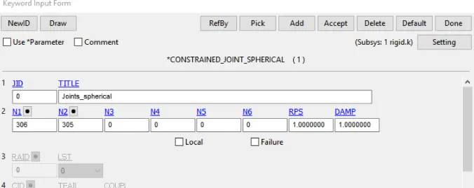
4.The extra nodes are entered in Key word Joint Spherical.
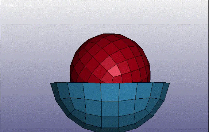
5.After rotational velocity is assigned to part 1 and part 2 is fixed using SPC
Case 2: deformable
1.For deformable case we need to create CNRB in place of extra nodes set
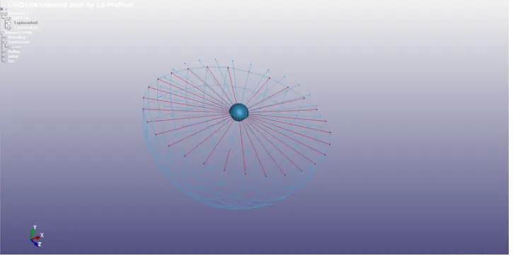
2.Also material card was cahnged from MAT rigid to Mat Elas
3.Also the velocity card is changed from Velocity rigid to initial Velocity
4.All other cards are similar to above
Cylindrical joints
Case 1: Rigids
1.Two cylindrical Shell is created using mesh option with two part ID's
2.Four nodes should be cretaed two pair of coincident nodes at the centre of the axis of the two shell elements
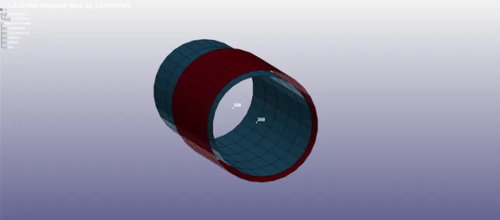
3.Similarly the extra nodes were assigned to parts using Constrained extra nodes set keyword
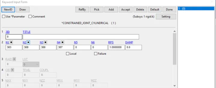
After this velocity is assigned to part 1 while part 2 is fixed using SPC
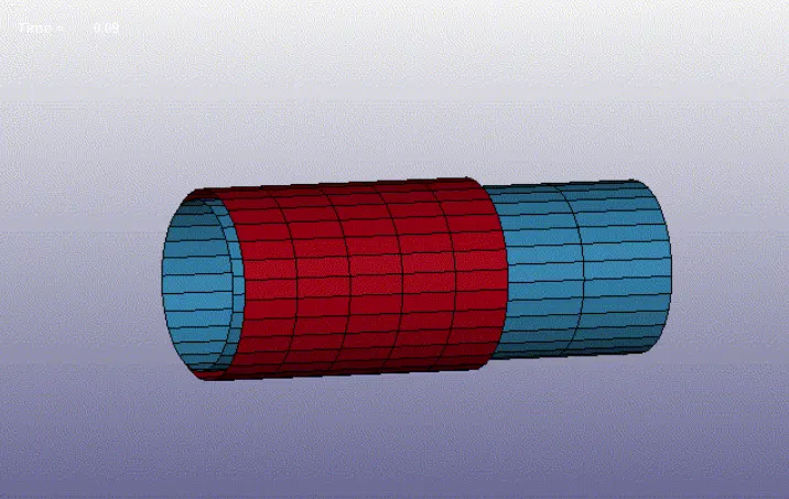
Case 2: Deformable
1.For deformable case we need to create CNRB's in place of extra nodes set
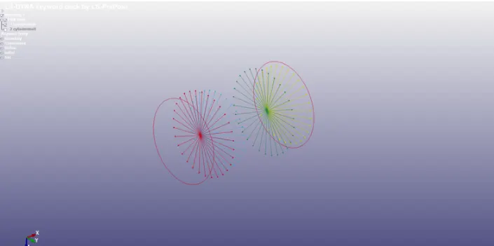
2.As the mat card is changed from rigid to elas
3.Also the velocity card is changed from rigid to intial
4.All other cards are similar to above
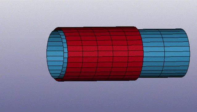
Translational Joints
Case 1: rigids
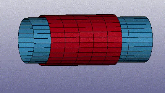
1.Two cylindrical Shell is created using mesh option with two part ID's.
2.Six nodes should be created with three pair of coincident nodes at the centre of axis of the two shells elements parts which is created
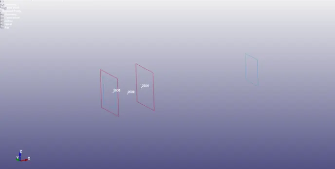
3.Similarly the extra nodes were assigned to parts using Constrained extra nodes set keyword
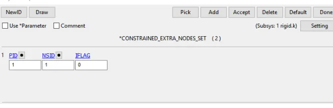
4.The coincident nodes are entered in Constrained Joint Translational
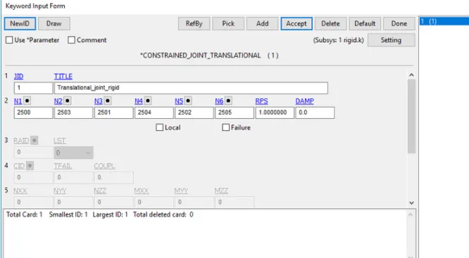
After this velocity is assigned to part 1 and part 2 is fixed using SPC
Case 2: deformable
1.For deformable case we need to create CNRB's in place of extra nodes set
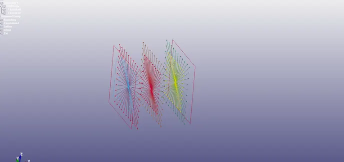
2.As the mat card is changed from rigid to elas
3.Also the velocity card is changed from rigid to intial
4.All other cards are similar to above
Conclusion : Hence created joints using the LS dyna keyword and came to know about diffferent joints in the solver