week-11 Joint creation and Demonstration
OBJECTIVE :
Using the manual (*CONSTRAINED_JOINT keyword) to demonstrate spherical, revolute, cylindrical, and translational joints between two rigid bodies and two deformable bodies.
PROCEDURE :
Between two rigid bodies
(1) Revolute joint
* Using the mesh option two parts are created as shown in below images.
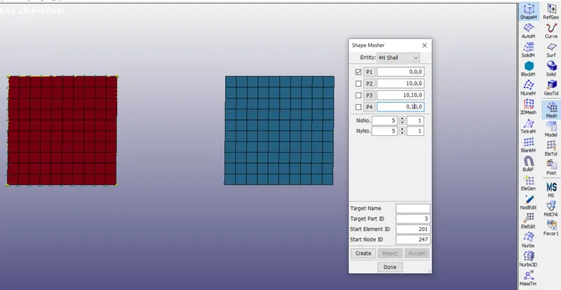
* MAT rigid is used to create the material and section of 1.5mm is created
* Material and section is assigned to the part.
* Two pair of extra nodes is created which is coincident and collinear using the option constrained_extra_nodes as shown in below image.
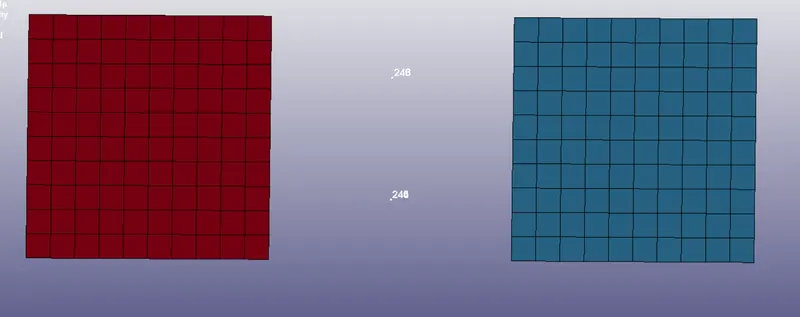
* Each pair is separately made the group using the set node option and that sets are assigned in the constrained extra node set option
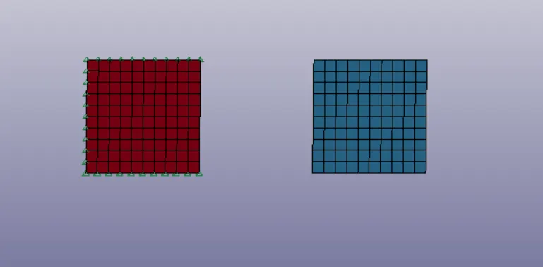
* Using the Boundary_spc_set, the highlighted set of nodes, as shown in below image are arrested in all DOF’s.
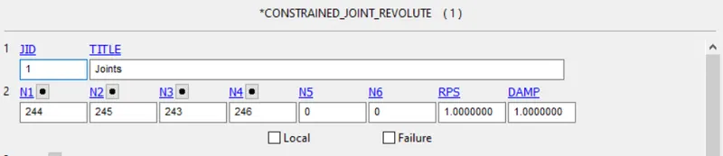
* The revolute joint is defined using the Constrained_revolute_joint and N1 and N3 are of rigid body 1 and N2 and N4 are of rigid body 2.
* Using the boundary_prescribed_motion displacement is defined and using the define_curve the load curve is defined and assigned in the boundary keyword.

* Control termination with 3 as ENDTIME and control timestep of 0.1e-7 dtint is defined.
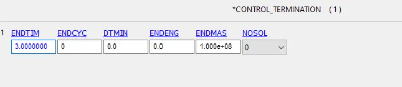
* Using the binary d3plot the output time step is defined.
(2) Spherical joint
* Procedure is same as revolute joint with some minor changes.
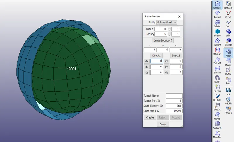
* Instead of 4 nodes Only 2 coincident nodes are created at the centre of the spherical object.
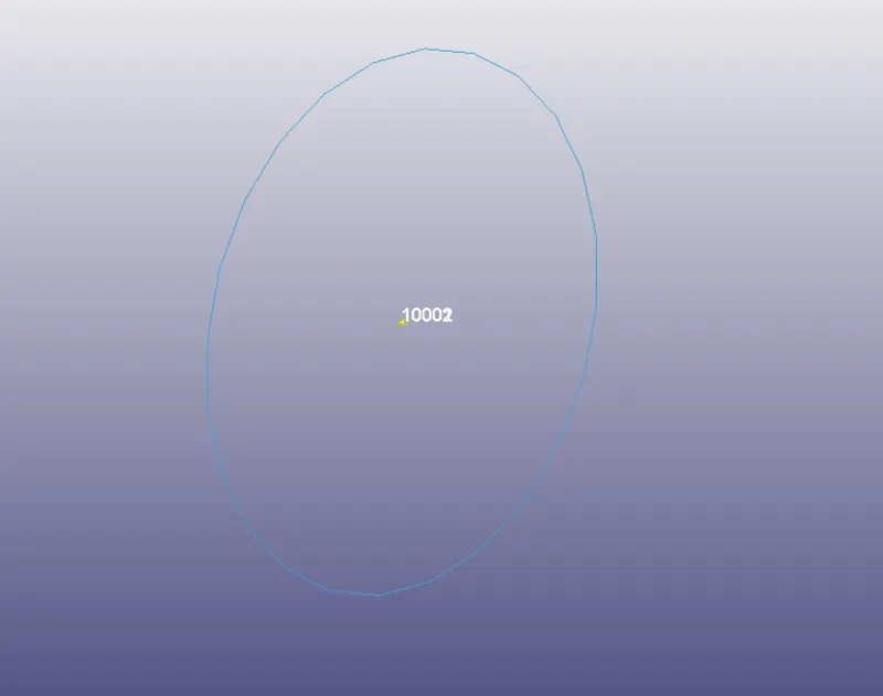
* Using the constrained extra nodes node option both nodes are constrained with different pid.
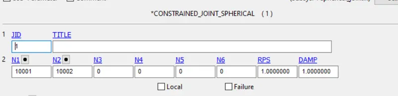
* Using the constrained joint spherical the two nodes N1 and N2 are defined of rigid body 1 and 2 respectively.
* Using the initial velocity rigid body the movement of the inside sphere is defined as shown in below image.
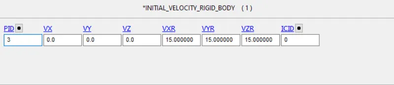
And all other steps are same as revolute joint.
(3) Cylindrical joint
* Procedure is same as revolute joint with some minor changes.
* Two set of nodes passing through centre line of cylinder is created as shown in below image.
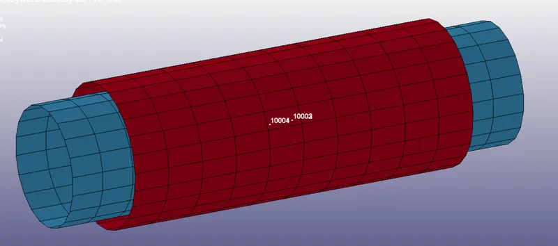
* Constrained joint cylindrical keyword is used to define the joint as shown in below image.
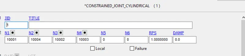
* Initial velocity rigid body is used to define the cylindrical movement as shown in below image.

* All other steps are same as revolute joint.
(4) Translational joint
* Procedure is same as revolute joint with some minor changes.
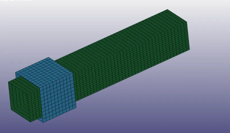
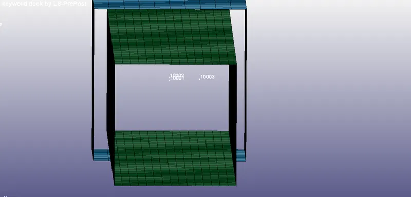
* Three pair of node set is created, where two node set are coincident and collinear and one other set is slightly displaced from the axis of the other pair of nodes as shown in below image.
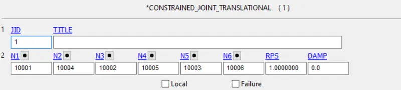
* Constrained joint translational keyword is used to define the joint as shown in below image.
* Initial velocity rigid body is used to define the movement as shown in below image.

* All other steps are same as revolute joint.
Between two deformable bodies
(1) Revolute joint
* Procedure is same as between two deformable bodies with some chenges.
* Changes are replacing the material card i.e, mat rigid to mat elastic.

* Another change is instead of constrained extra nodes the constrained nodal rigid body card is used which as some shared nodes with deformable body.
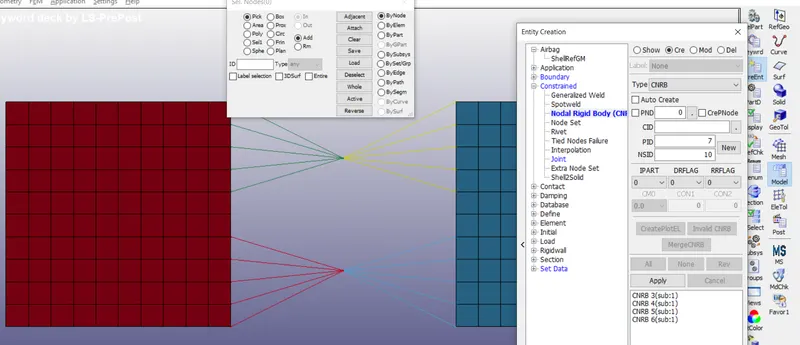
* All other steps are similar to what as done before between the two rigid bodies.
(2) Spherical joint
* Procedure is same as between two rigid bodies with some chenges.
* Changes are replacing the material card i.e, mat rigid to mat elastic.
* Another change is instead of constrained extra nodes the constrained nodal rigid body card is used which as some shared nodes with deformable body.
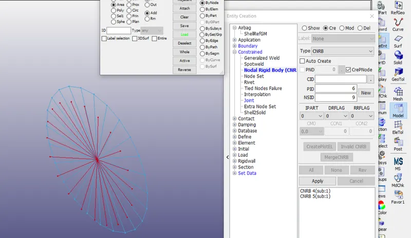
* All other steps are similar to what as done before between the two rigid bodies.
(3) Cylindrical joint
* Procedure is same as between two rigid bodies with some chenges.
* Changes are replacing the material card i.e, mat rigid to mat elastic.
* Another change is instead of constrained extra nodes the constrained nodal rigid body card is used which as some shared nodes with deformable body.
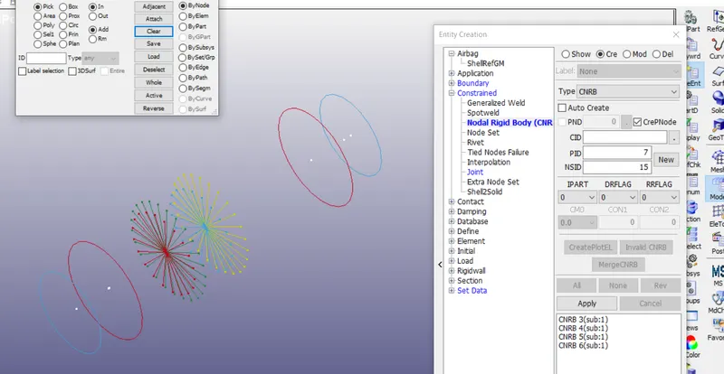
* All other steps are similar to what as done before between the two rigid bodies.
(4) Translational joint
* Procedure is same as between two rigid bodies with some chenges.
* Changes are replacing the material card i.e, mat rigid to mat elastic.
* Another change is instead of constrained extra nodes the constrained nodal rigid body card is used which as some shared nodes with deformable body.
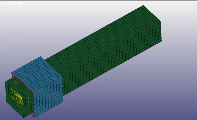
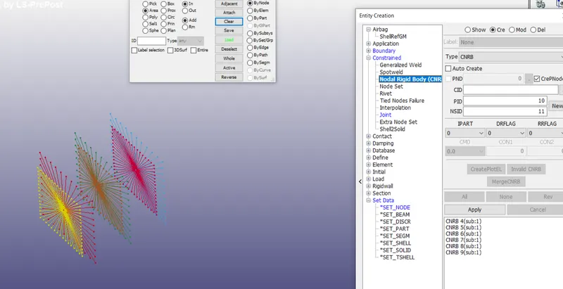
* All other steps are similar to what as done before between the two rigid bodies.
Results:
https://drive.google.com/drive/folders/1JrhRklIRvcGgjfOl2BNzQ9G5y82Td76M?usp=sharing
Note: All the joint demonstration GIF file is attached in the google drive, link is attached in the result
Conclusion:
As per the objective the spherical, revolute, cylindrical, and translational joints between two rigid bodies and two deformable bodies is built on the software and demonstartion is carried out.