week-11 Joint creation and Demonstration
JOINTS: There are different number of joints that are using in the industry. They are
- Revolute Joint.
- Spherical Joint.
- Cylindrical Joint.
- Translational Joint.
AIM: To create the Different joints in LS_DYNA and simulate them and show the animations of the joints with Rigid bodies and Deformable bodies.
PROCEDURE:
REVOLUTE JOINT USING RIGID BODIES:
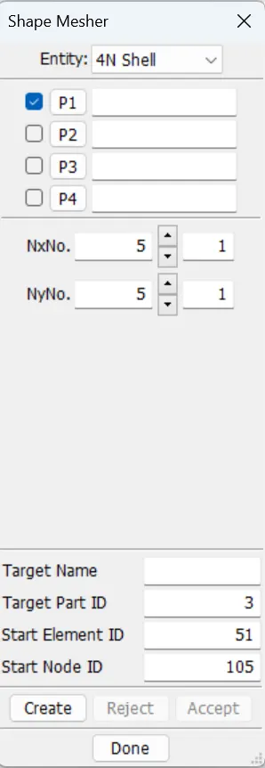
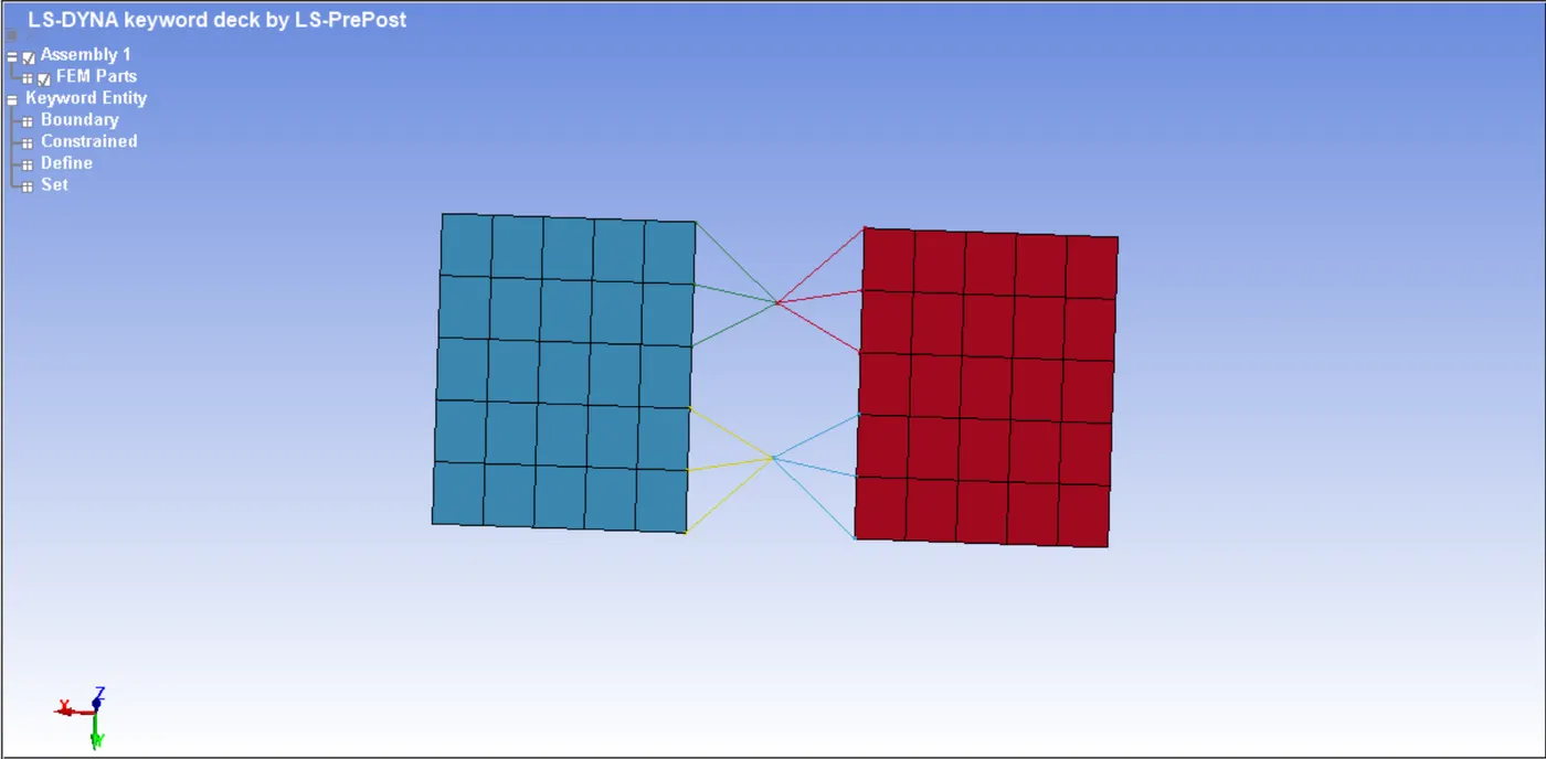
- First using the shape mesher using Elements and tools, create 2 rectangular plates using 4N shell with dimensions 75x100 by leaving a gap of 50 in x-direction.
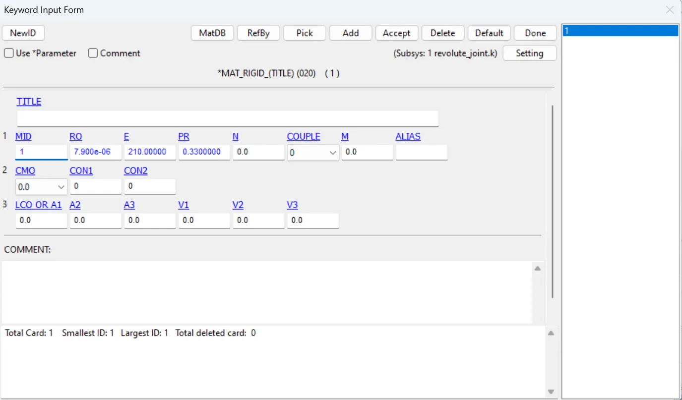
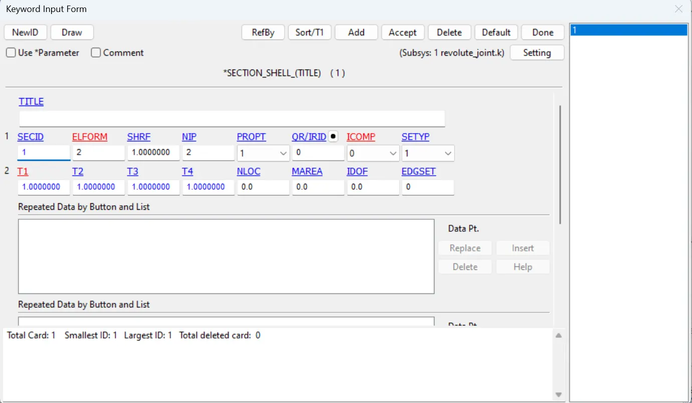
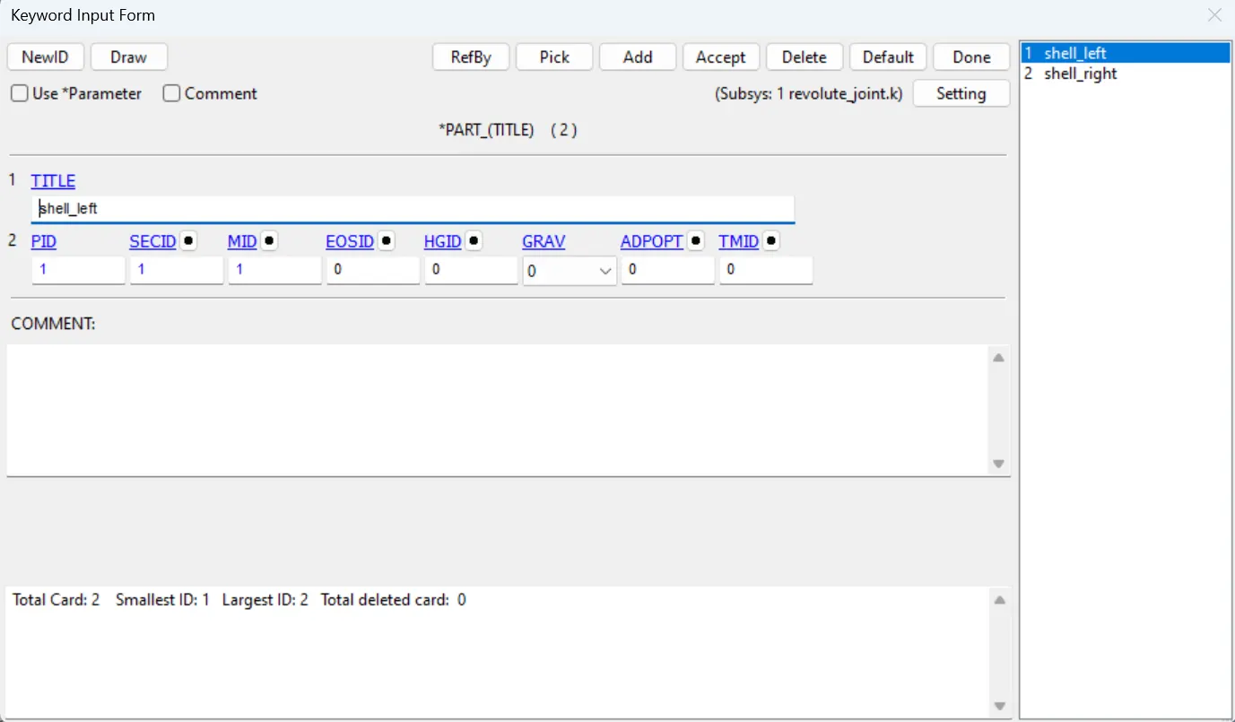
- Then create the Mat_rigid material and Section with thickness 1mm and assign the material and section to their respective parts.
- Using the Elements and Mesh> node editing create the nodes in between the two plates 2 for each plate.
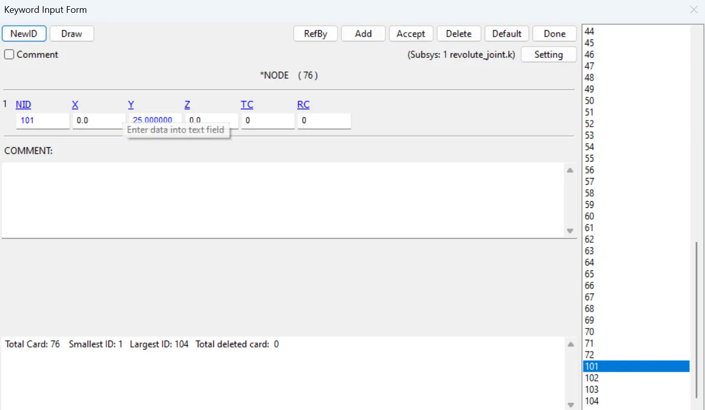
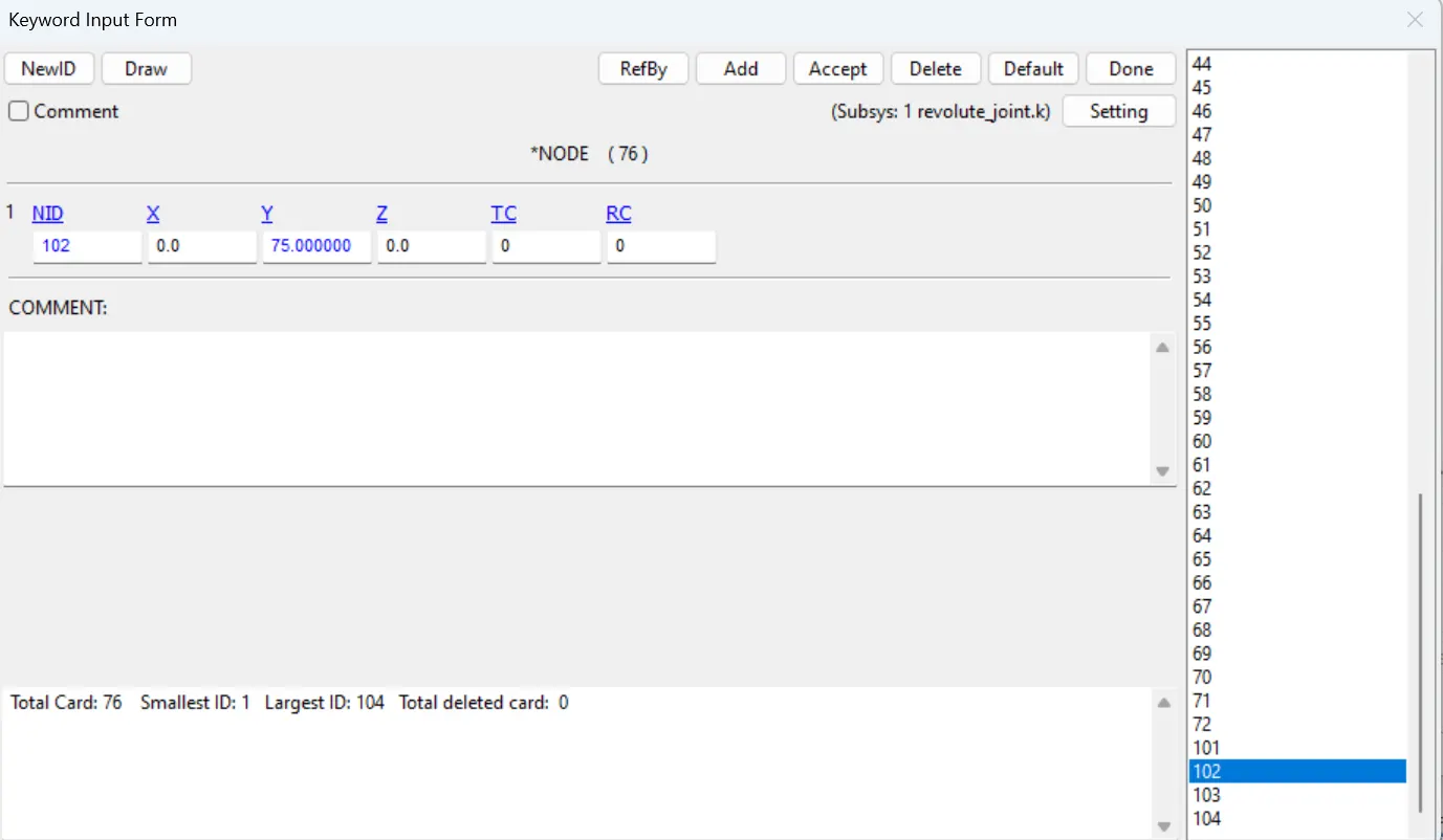
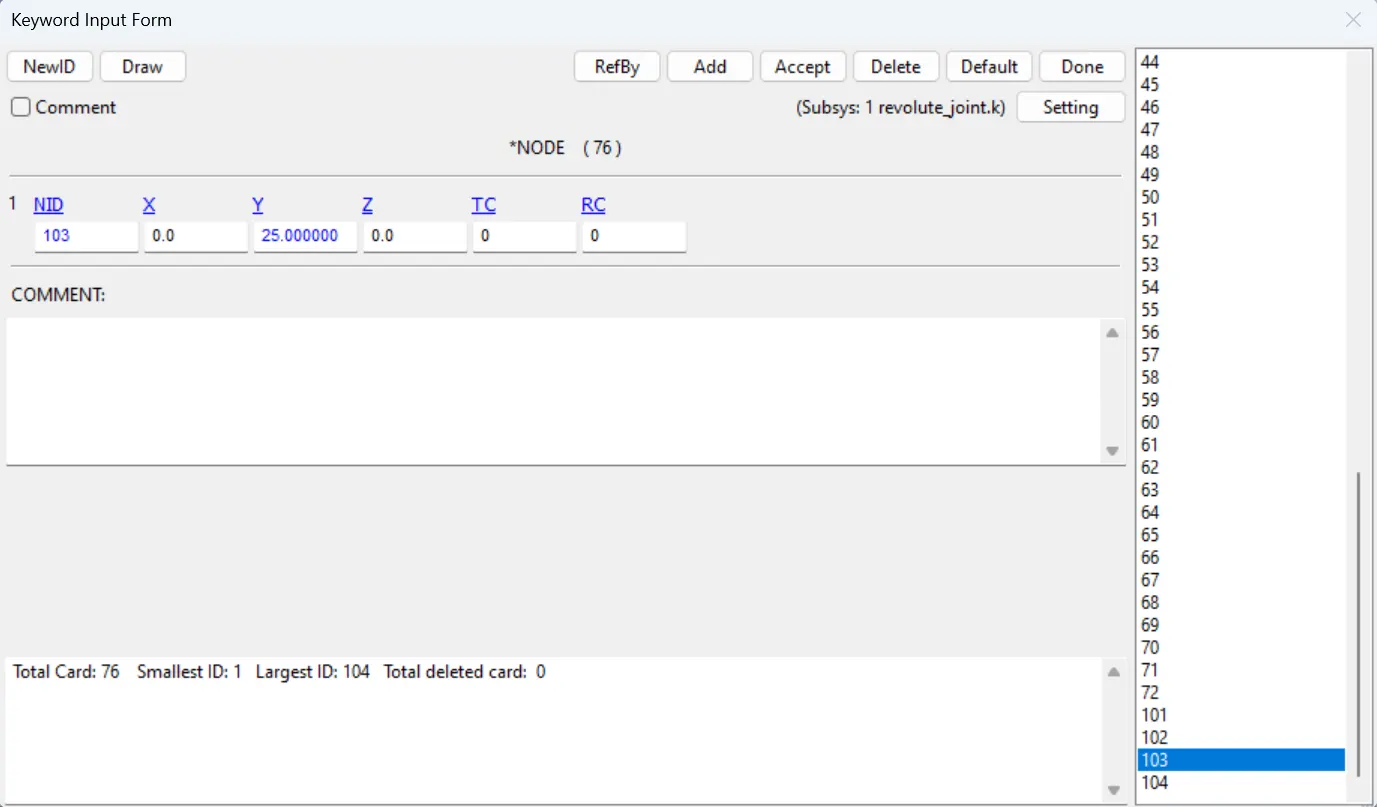
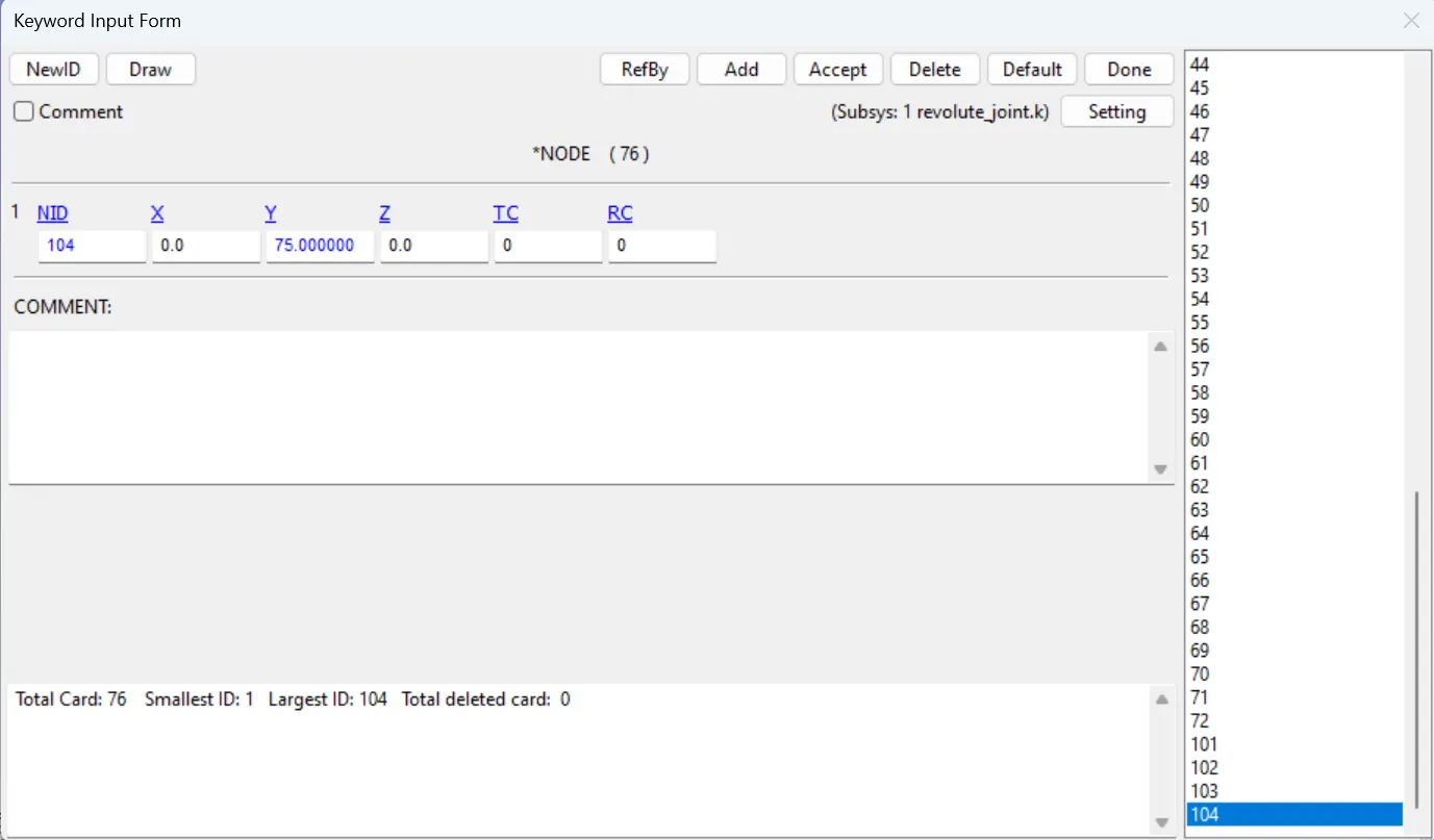
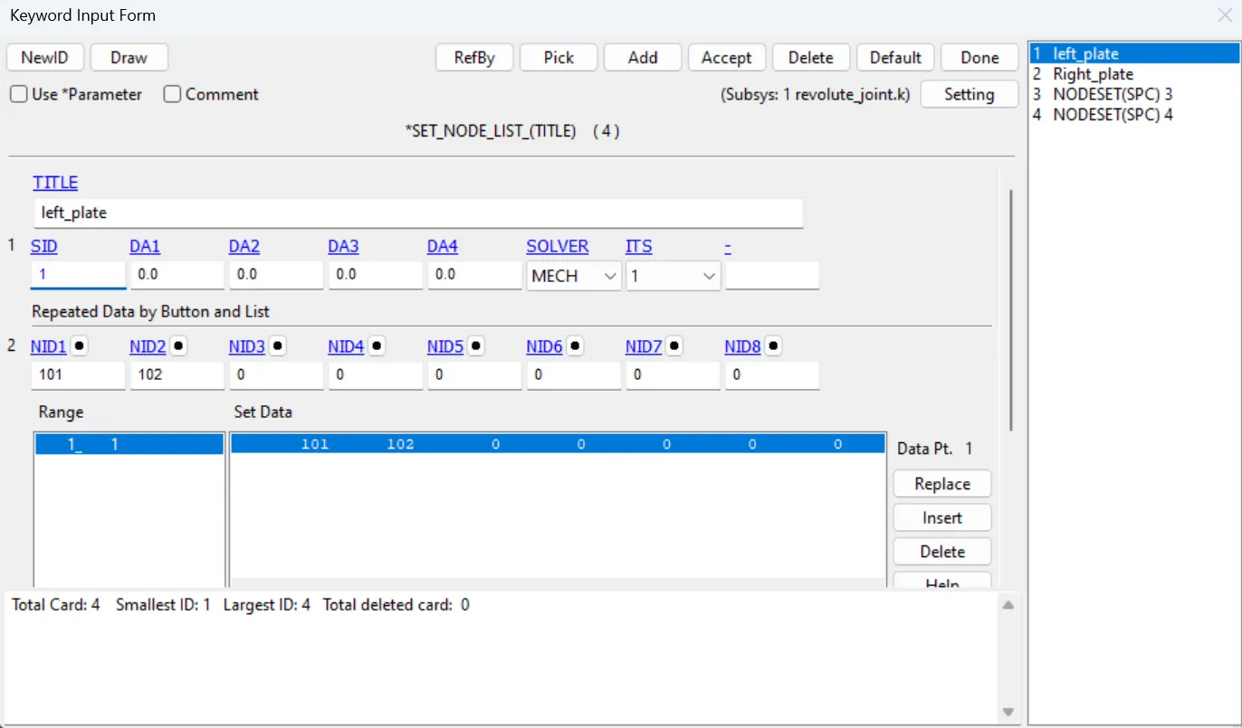
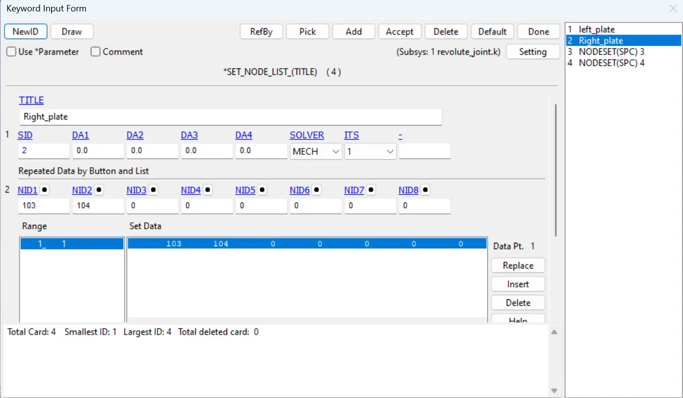
- Create two node sets by using the model & keywords> create entity> set_node using the nodes created above, 101 and 102 one node set and 103 and 104 second node set.
- Assign the node set1 to part 1 and node set 2 to part 2 using the constrained_extra_nodeset card in model&keywords> all> constrained.
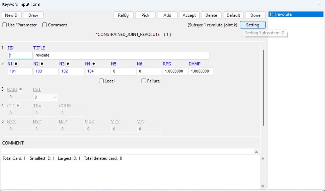
- Use constrained_joint_revolute card in Model&keywords> all> constrained, assign the N1,N3 for part 1 and N2, N4 for Part 2.
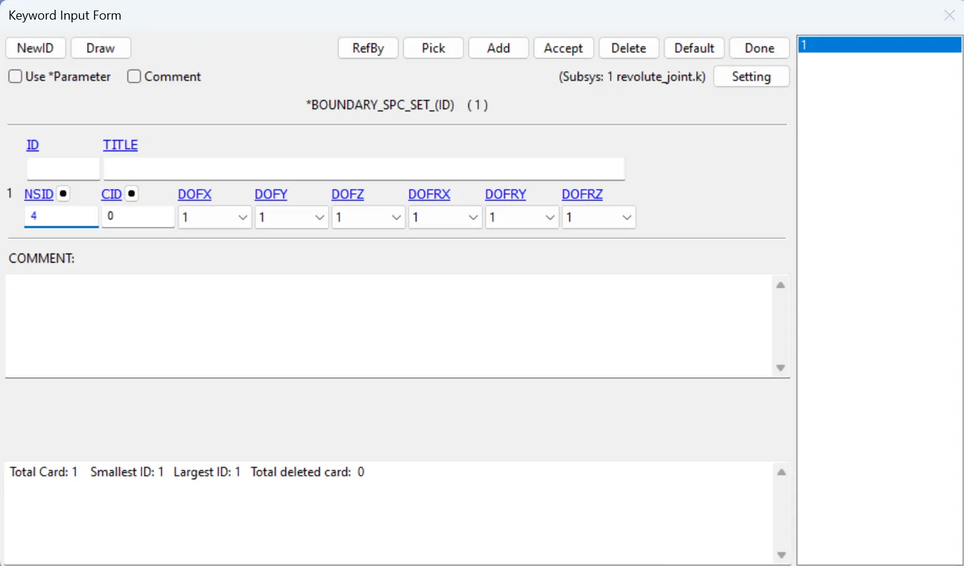
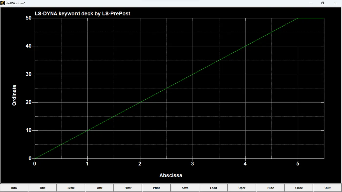
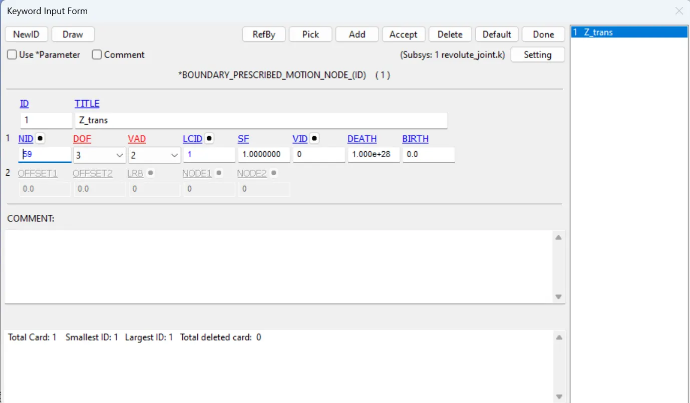
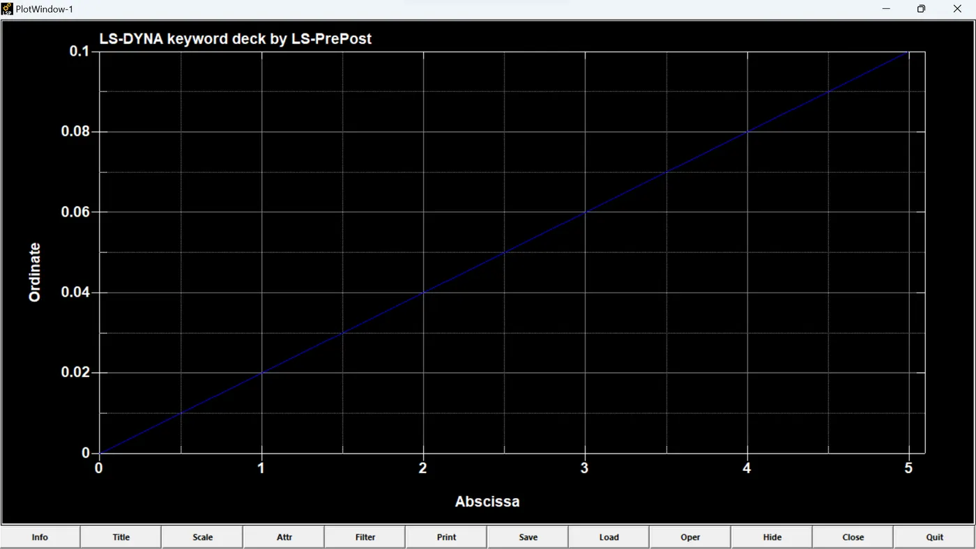
- After creating the joint we need to create the boundary conditions by fixing the edges of the left plate except the edge near the joint and a node is selected on the second part and assign the displacement as curve shown in the figure.
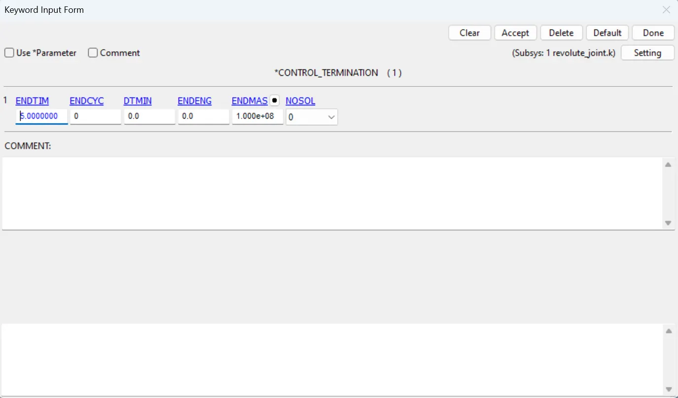
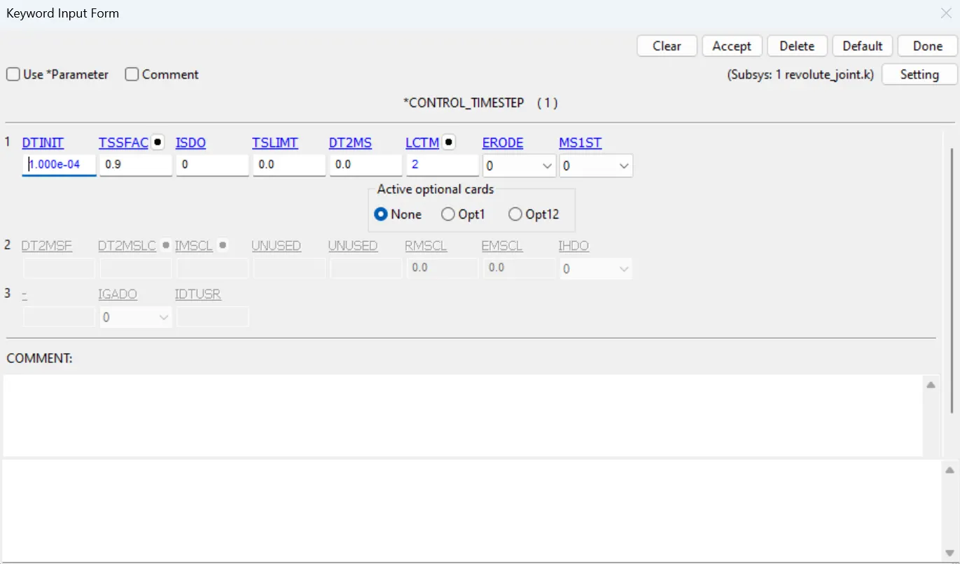
- Lastly we need to create the control termination card with time step with endtime as 5ms and control timestep card to control the time step with the curve as shown in figure.
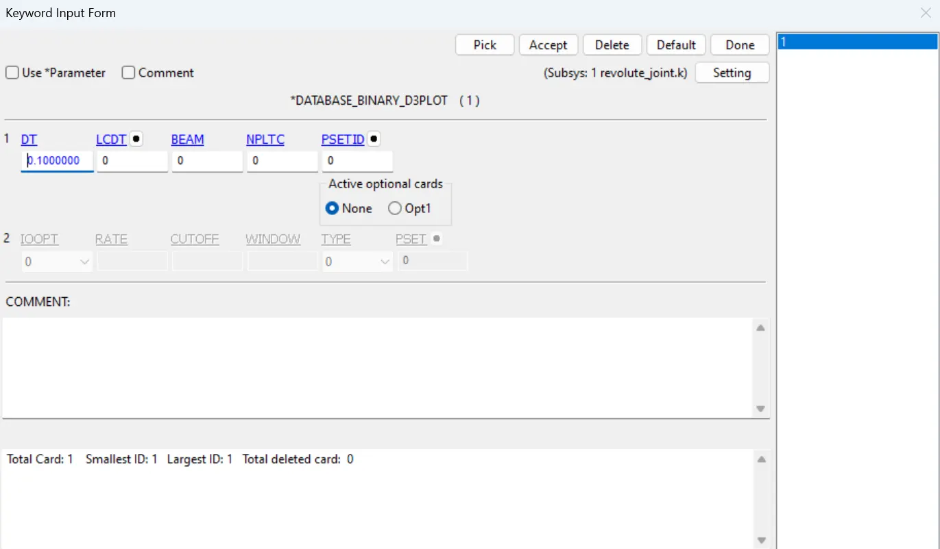
- Give the database d3plot with dt as 0.1 seconds.
REVOLUTE JOINT DEFORMABLE:
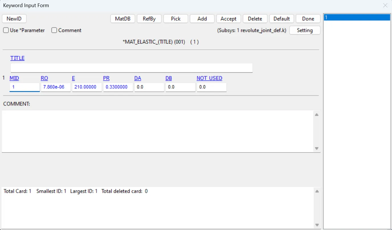
- Here all the steps are similar except the material is changed from the Mat_Rigid to Mat_Elastic.
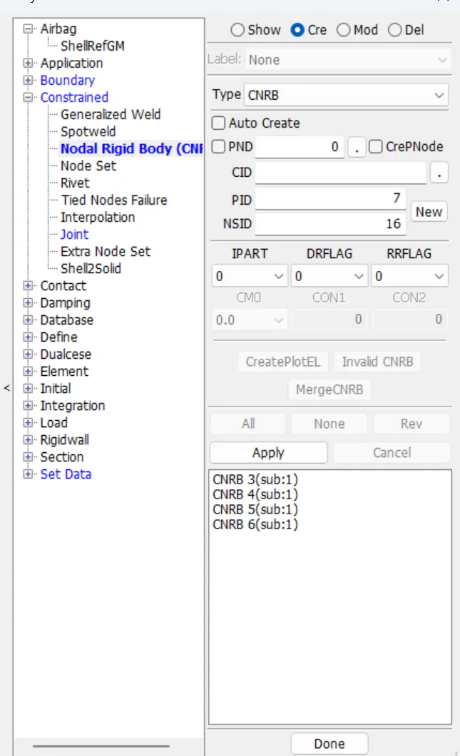
- For the deformable bodies the we need to create the Constrained_Nodal_Rigid_bodies(CNRB) card which is in Model&keywords> create entity> Constarined. First uncheck the Pnode and then select the 101 node and select the nodes which are nearer to that point repeat the same procedure for the remaining 102,103,104. After creating the CNRBs we need to create the joint using the those 4 nodes.
SPHERICAL JOINT RIGID:
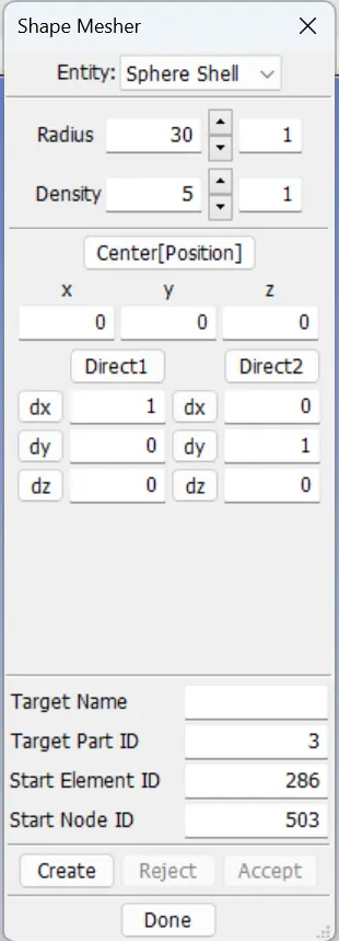
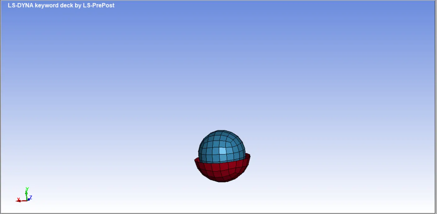
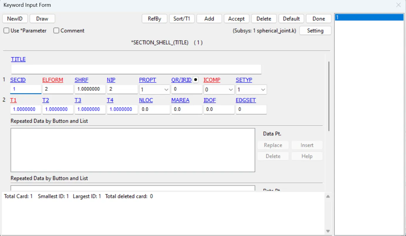
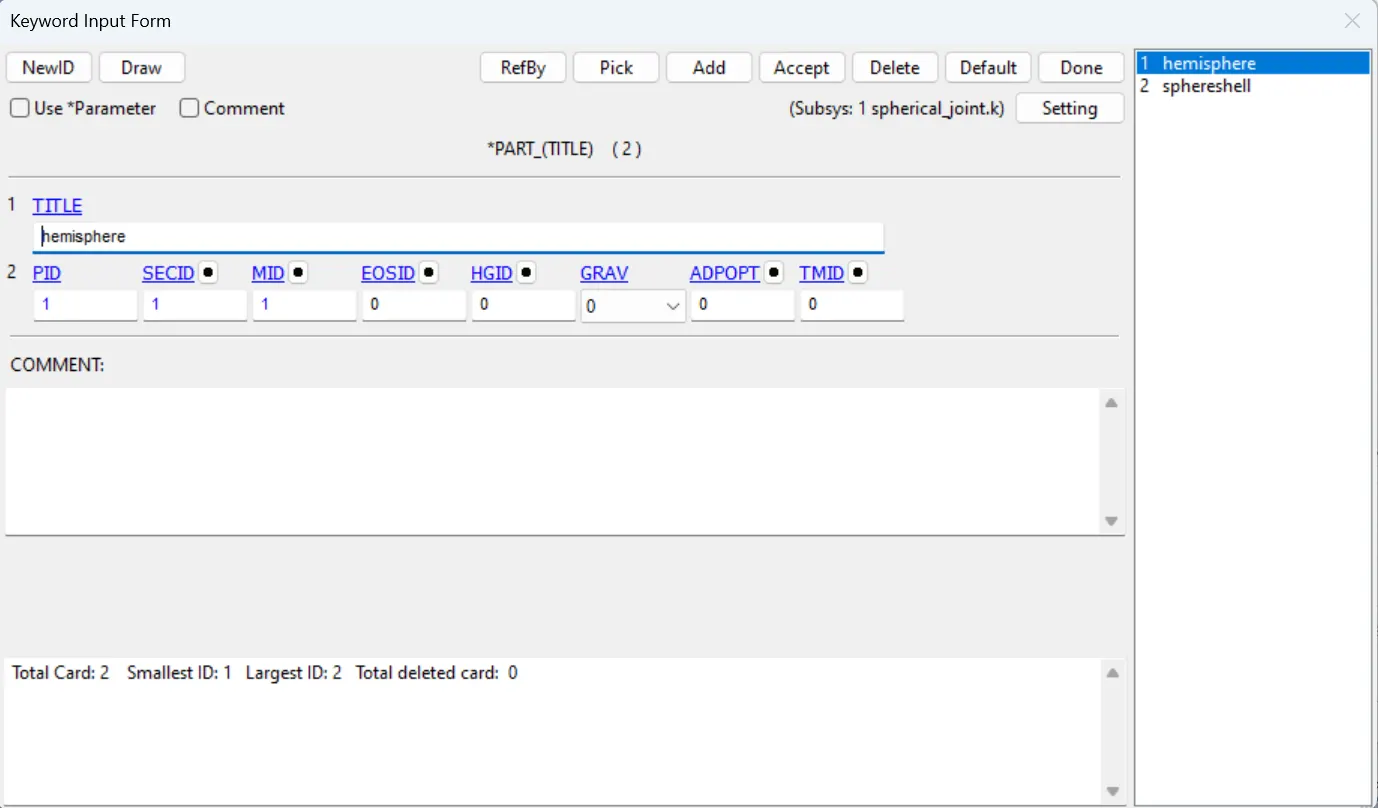
- First using the shape mesher using Elements and tools, create 2 spheres using spherical shell with dimensions 30,25 radius and 5 density. By using the Element Editing in Elements and tools delete the elements which are in the upper half of the bigger sphere which creates the Hemisphere.
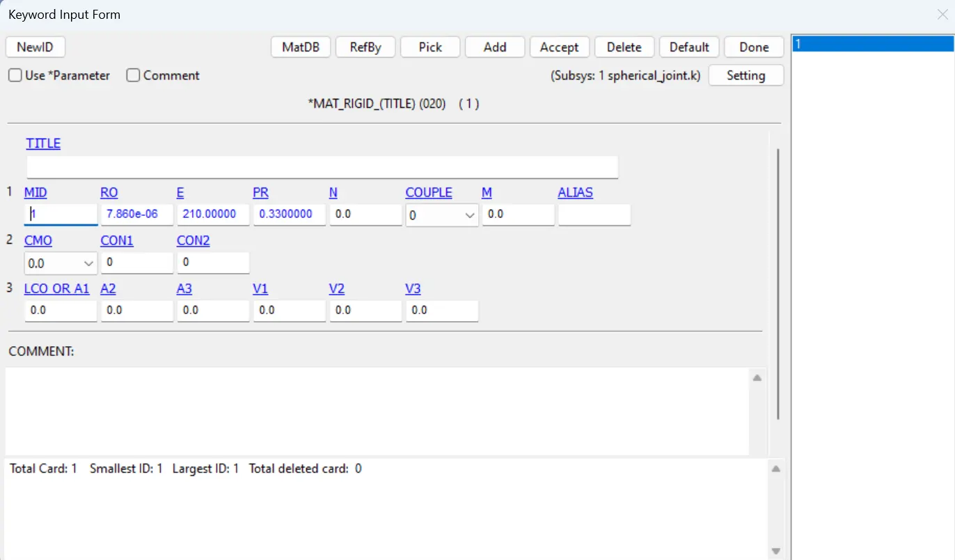
- Then create the Mat_rigid material and Section with thickness 1mm and assign the material and section to their respective parts.
- Using the Elements and Mesh> node editing create the nodes at the center of two spheres, 1 for each plate.
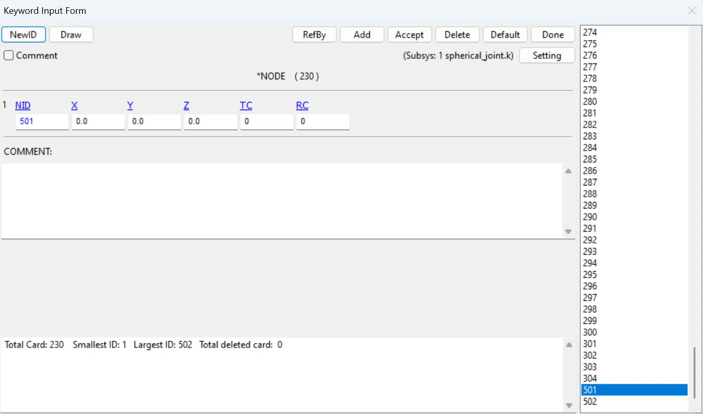
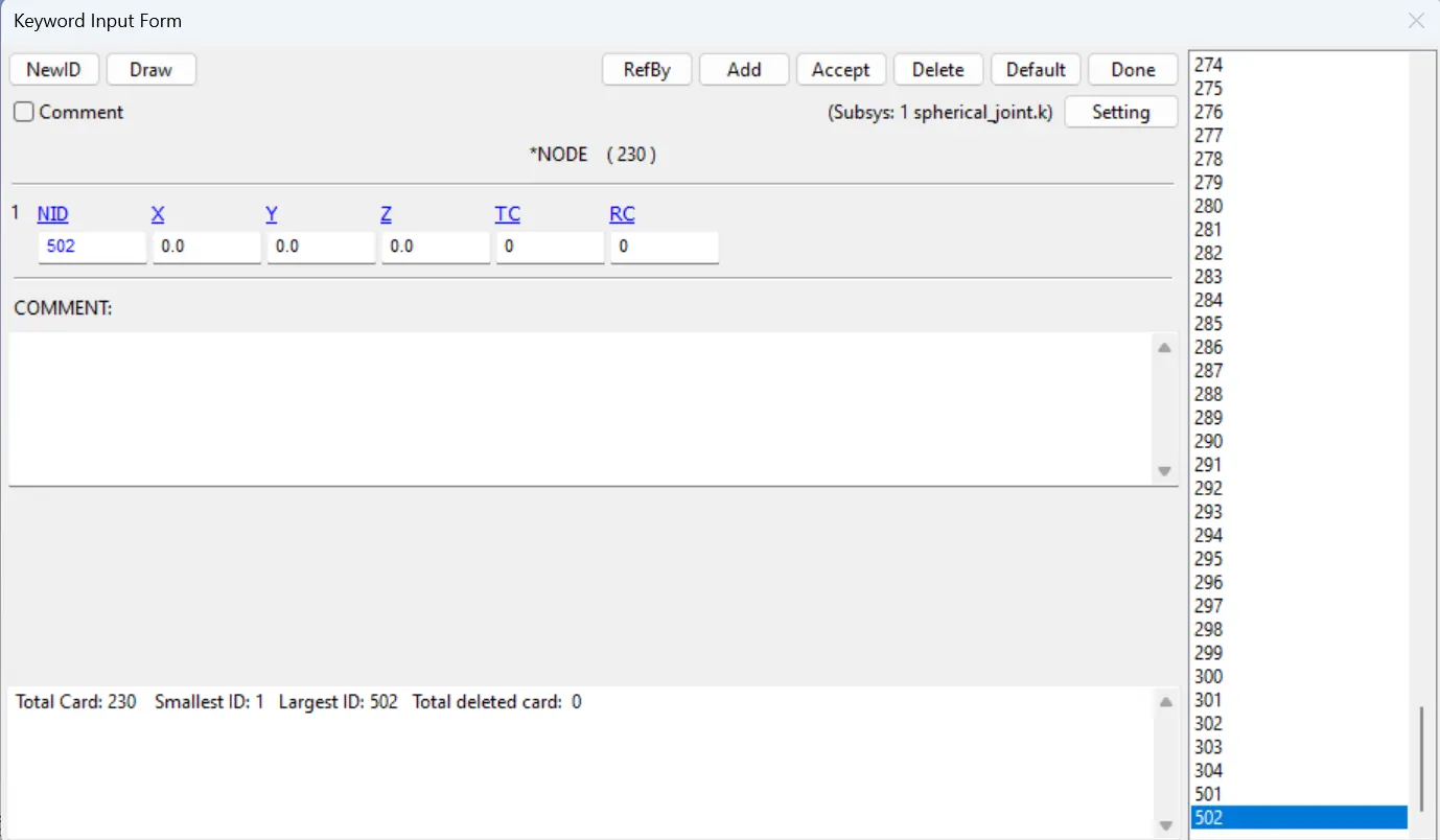
- Assign the node 501 to part 1 and node 502 to part 2 using the constrained_extra_nodeset card in model&keywords> all> constrained.
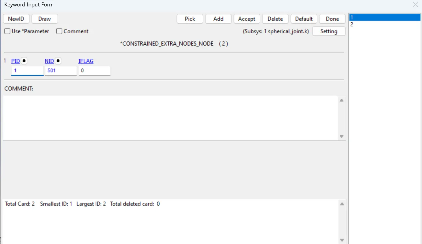
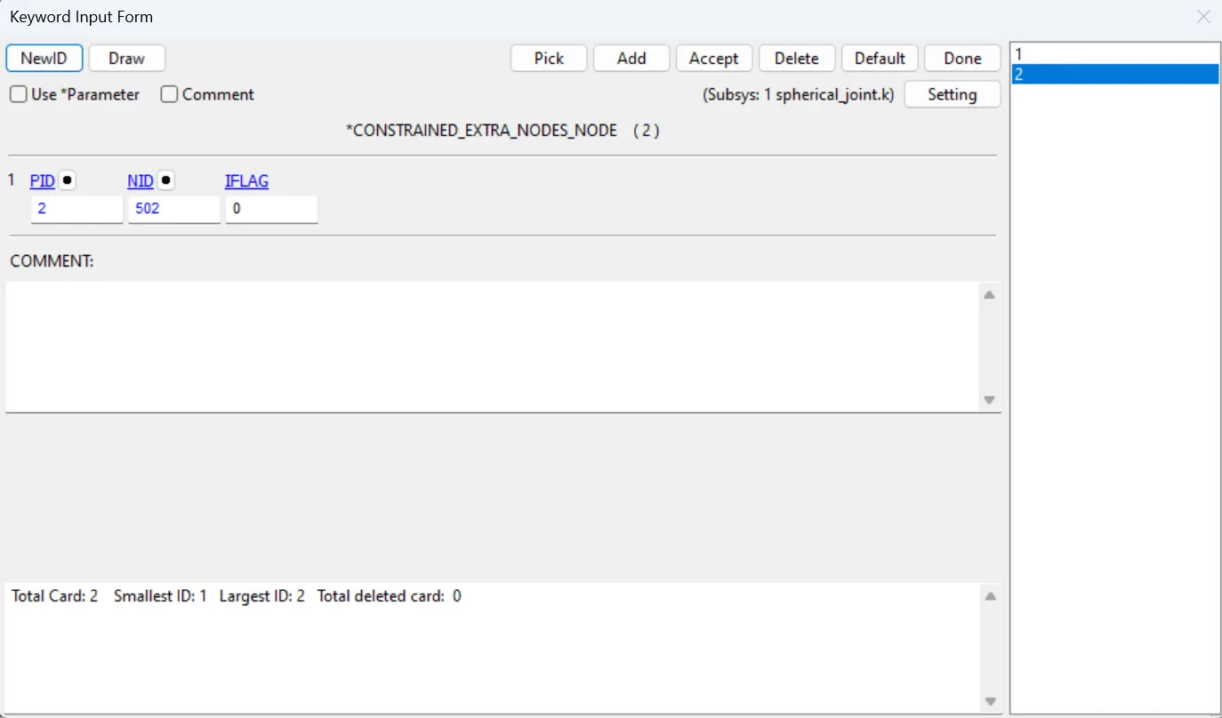
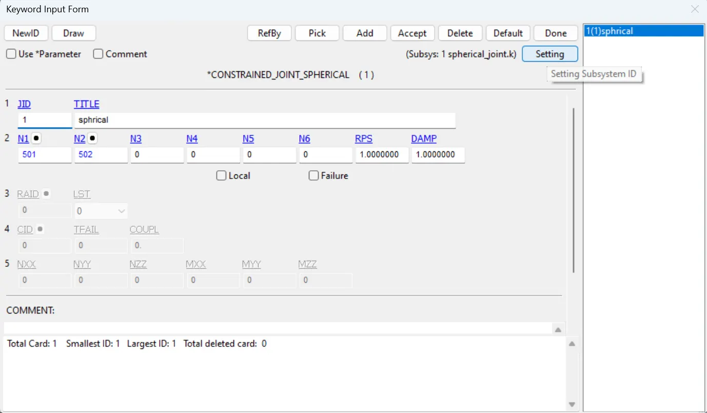
- Use constrained_joint_spherical card in Model&keywords> all> constrained, assign the N1 for part 1 and N2 for Part 2.
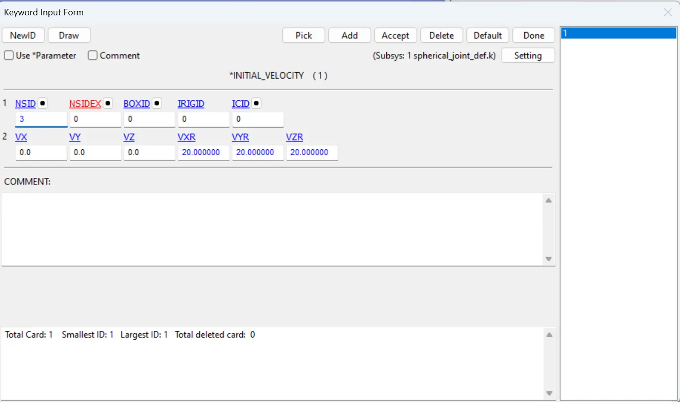
- After creating the joint we need to create the Initial velocity card for rigid bodies with angular velocity as 20,20,20mm/ms
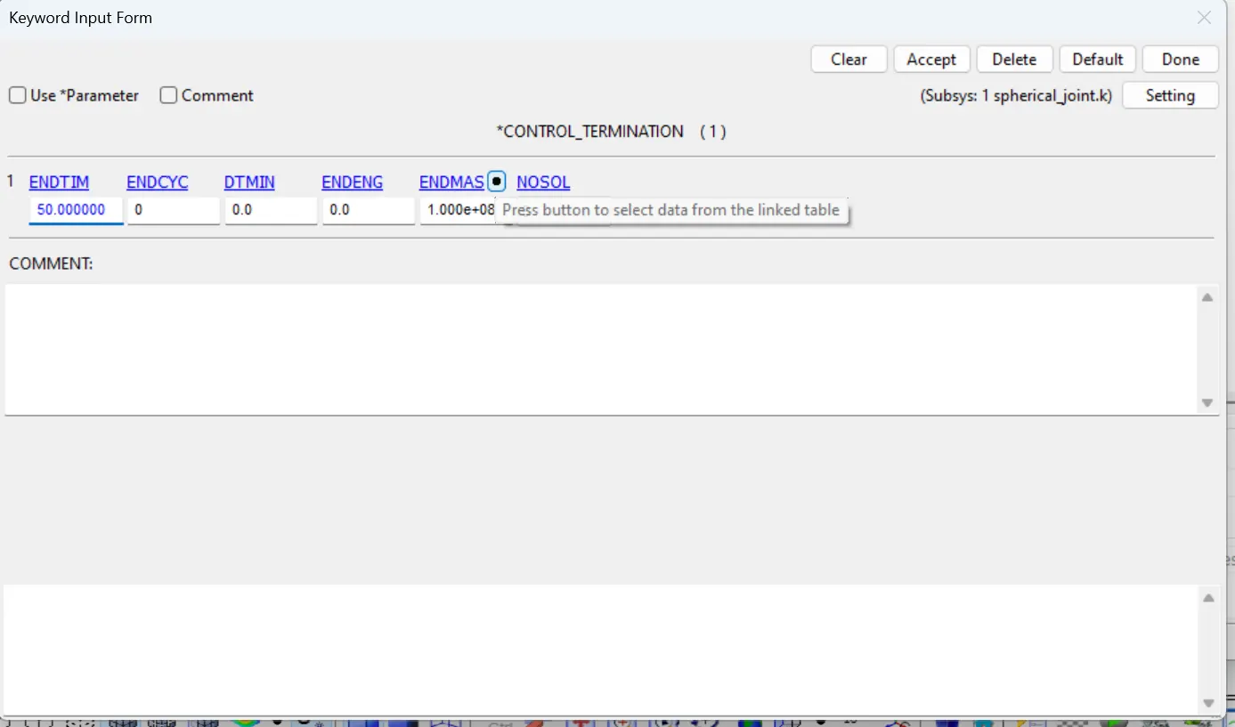
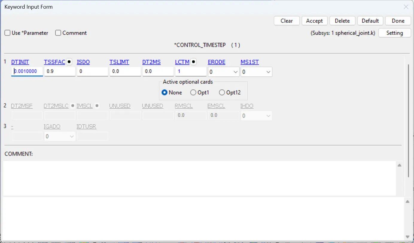
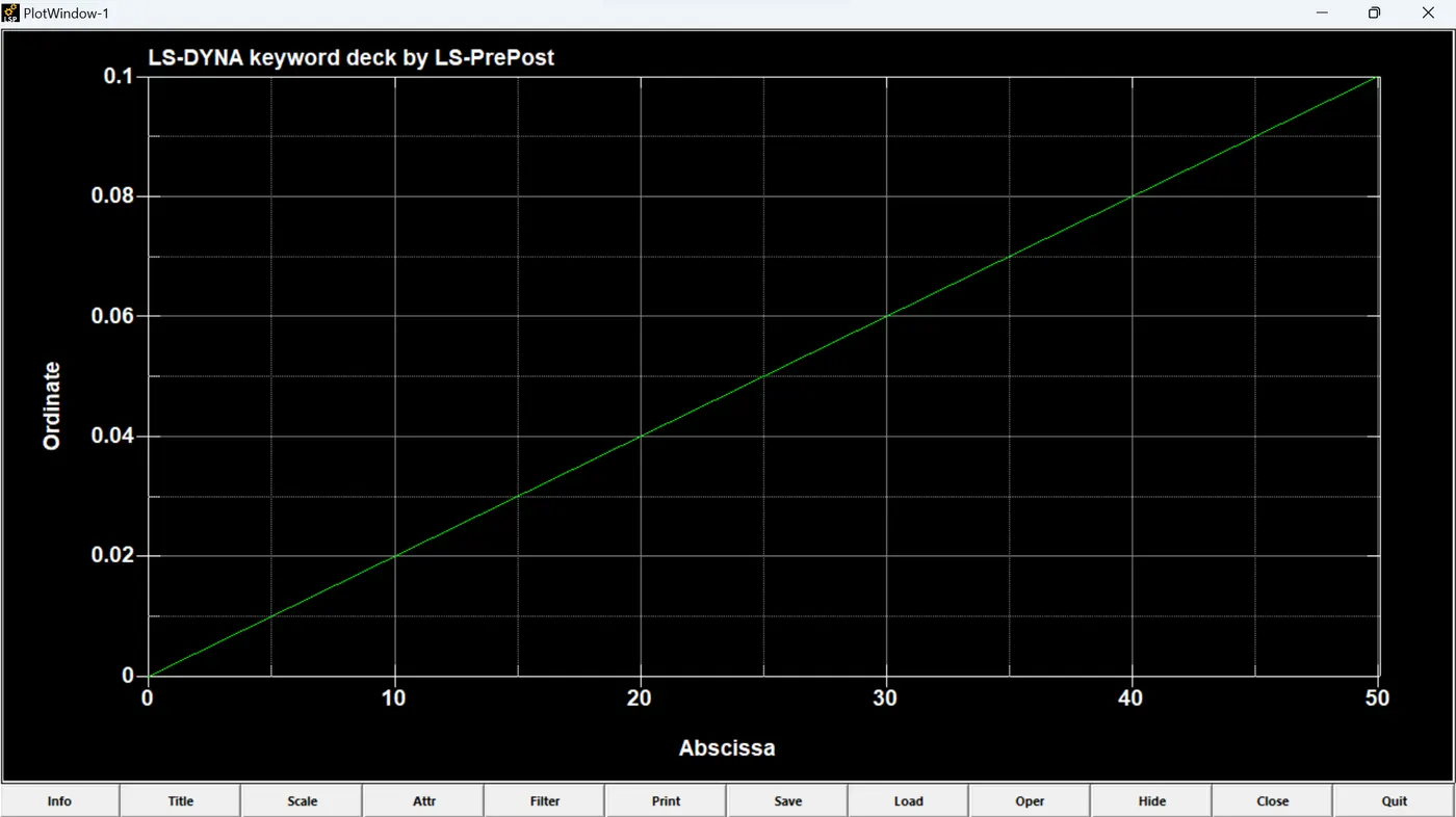
- Lastly we need to create the control termination card with time step with endtime as 50ms and control timestep card to control the time step with the curve as shown in figure.
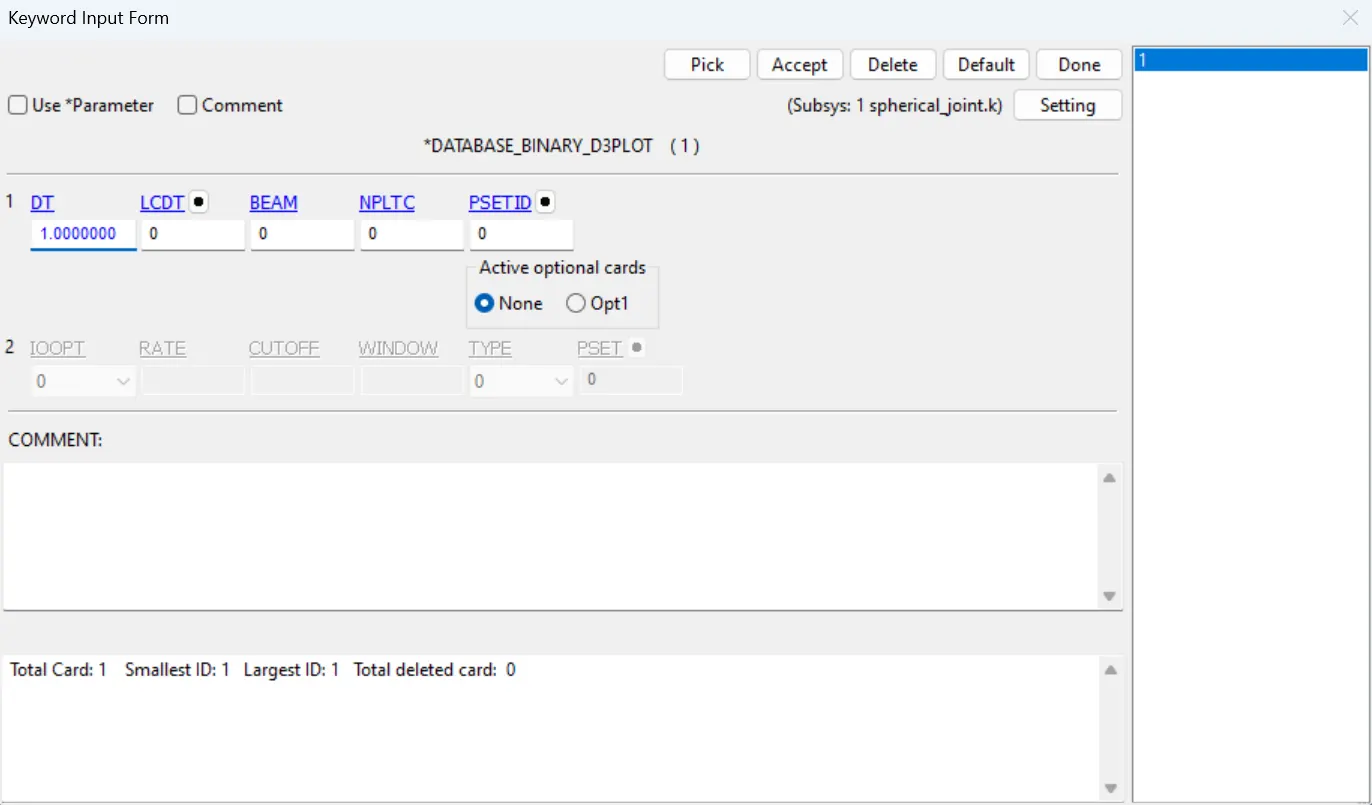
- Give the database d3plot with dt as 0.1 seconds.
SPHERICAL JOINT DEFORMABLE:
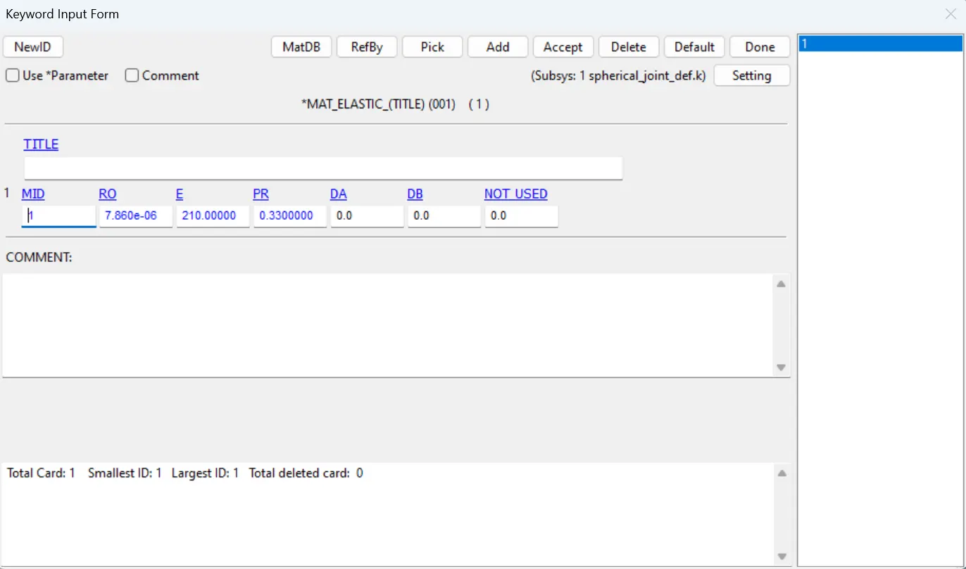
- Here all the steps are similar except the material is changed from the Mat_Rigid to Mat_Elastic.
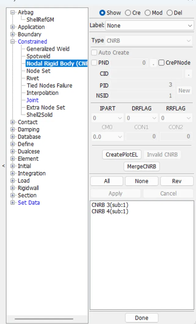
- For the deformable bodies the we need to create the Constrained_Nodal_Rigid_bodies(CNRB) card which is in Model&keywords> create entity> Constarined. First uncheck the Pnode and then select the 501 node and select the nodes which are nearer to that point repeat the same procedure for the remaining 502. After creating the CNRBs we need to create the joint using the those 2 nodes.
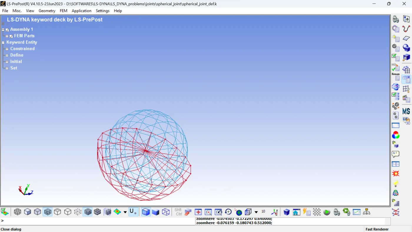
- initial velocity Rigid bodies has to be changed to Initial velocity and give the rotational velocities as 20, 20, 20 in X,Y,Z directions.
CYLINDRICAL JOINT RIGID:
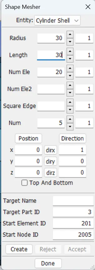
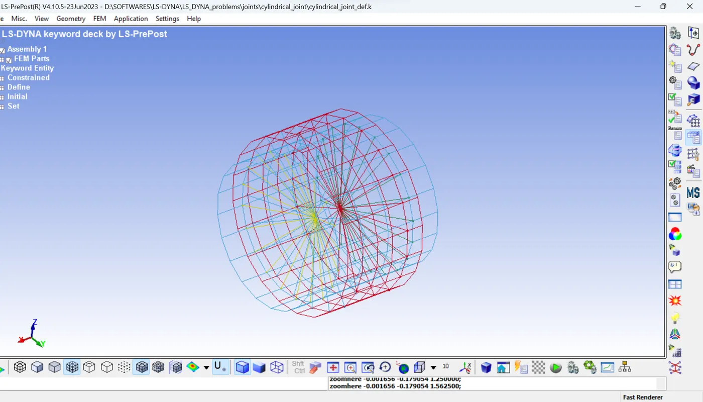
- First using the shape mesher using Elements and tools, create 2 cylinders using cylindrical shells with radius, height and number of elements as 30,30 and 20 for 1st cylinder, 25,50,20 for the second cylinder.
- Then create the Mat_rigid material and Section with thickness 1mm and assign the material and section to their respective parts.
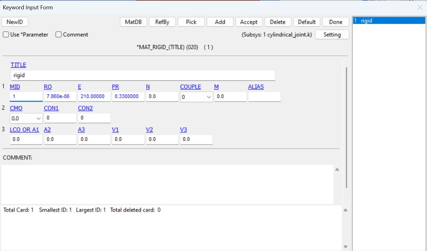
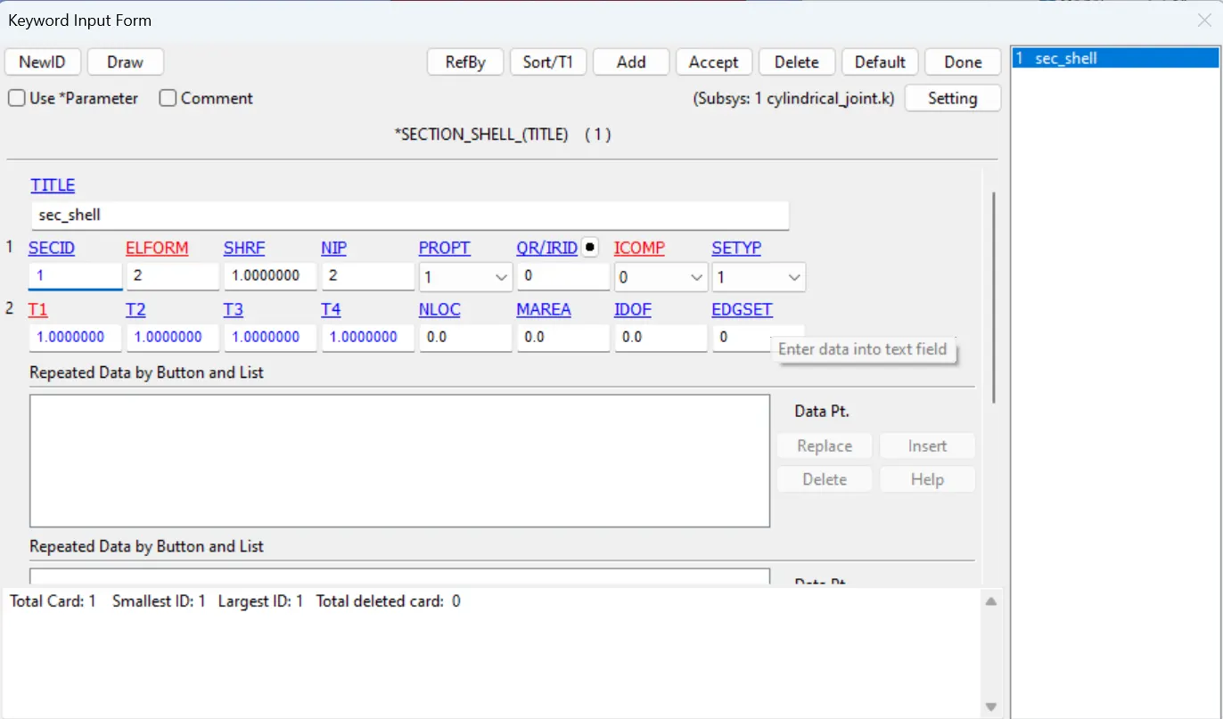
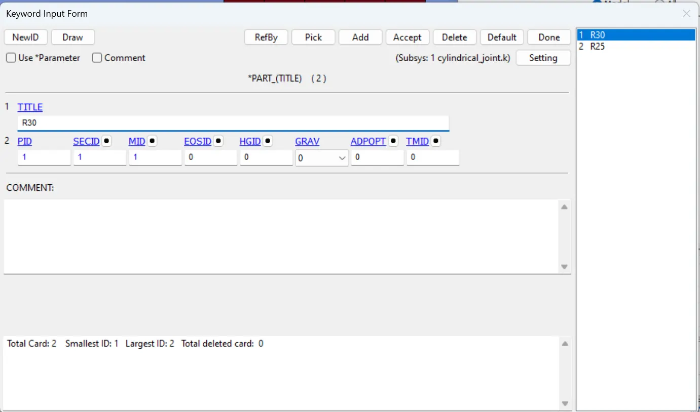
- Using the Elements and Mesh> node editing create the nodes at the center of the 2 cylinders, 2 for each cylinder.
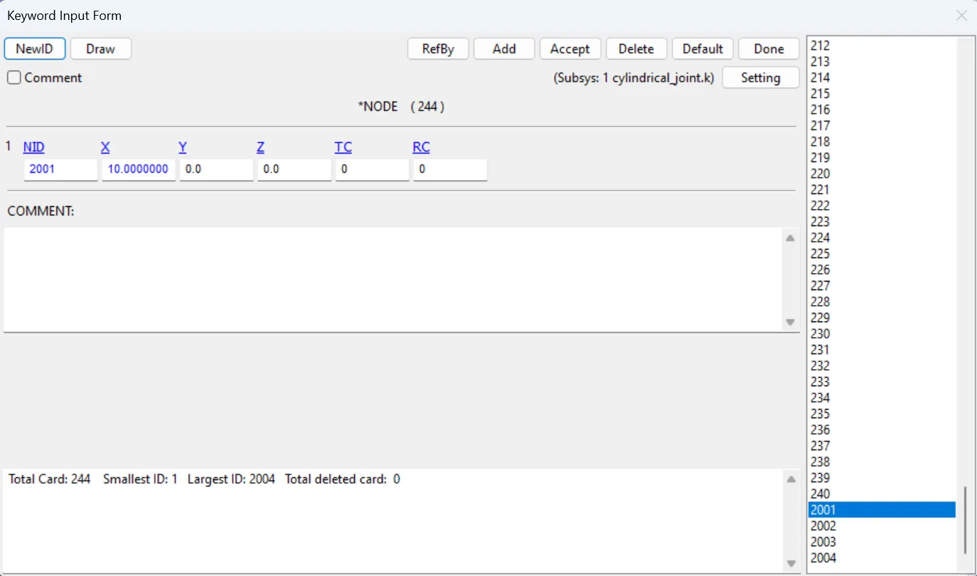
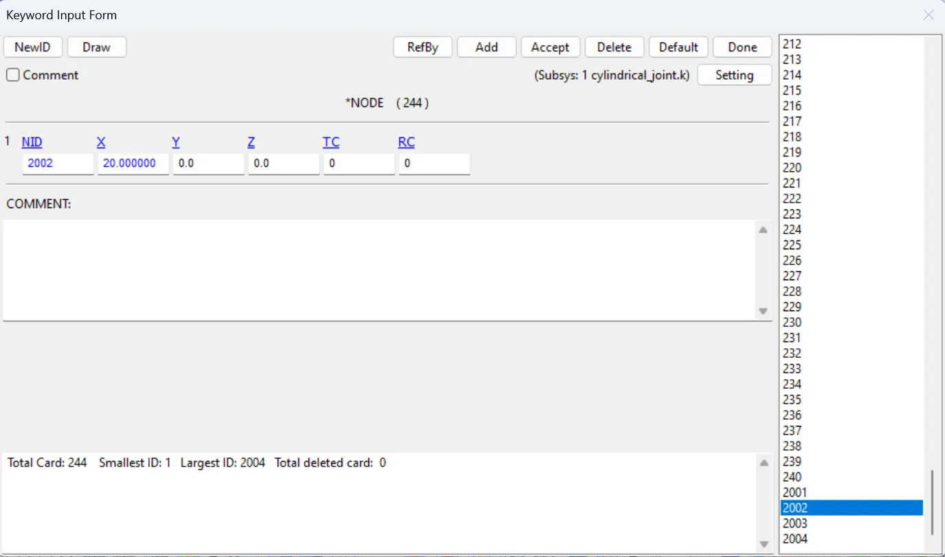
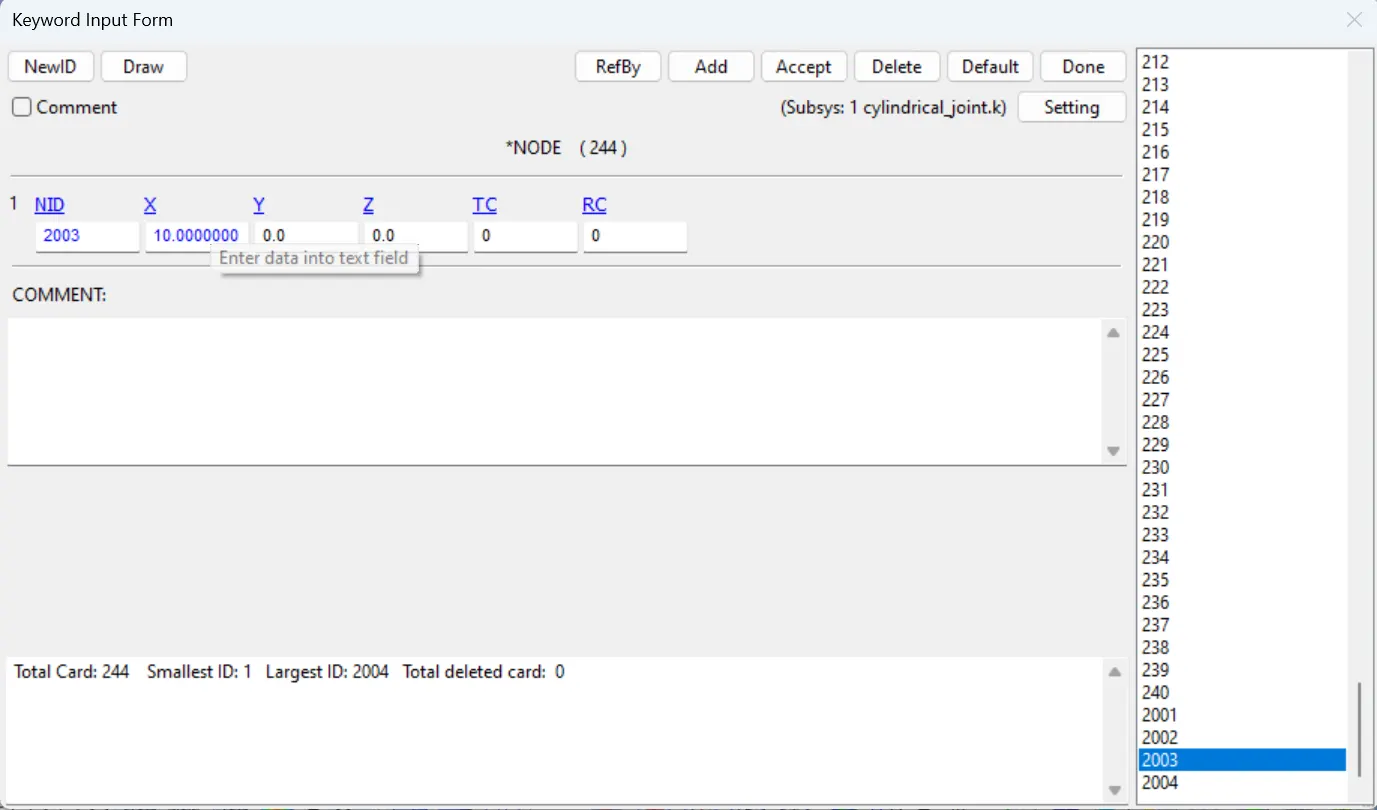
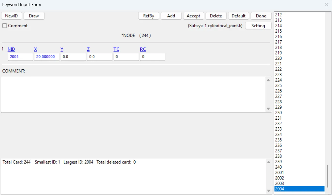
- Create two node sets by using the model & keywords> create entity> set_node using the nodes created above, 2001 and 2002 one node set and 2003 and 2004 second node set.
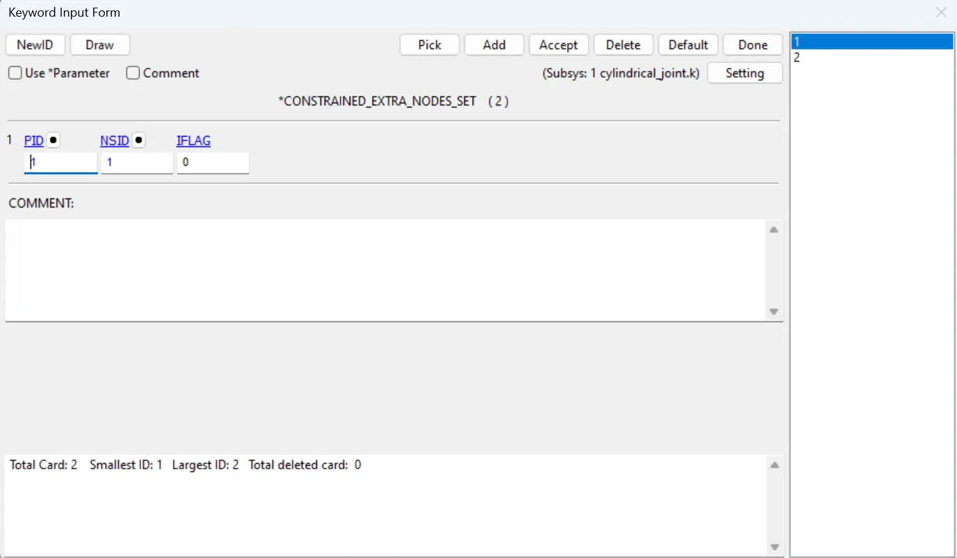
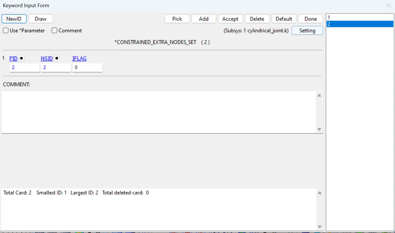
- Assign the node set1 to part 1 and node set 2 to part 2 using the constrained_extra_nodeset card in model&keywords> all> constrained.
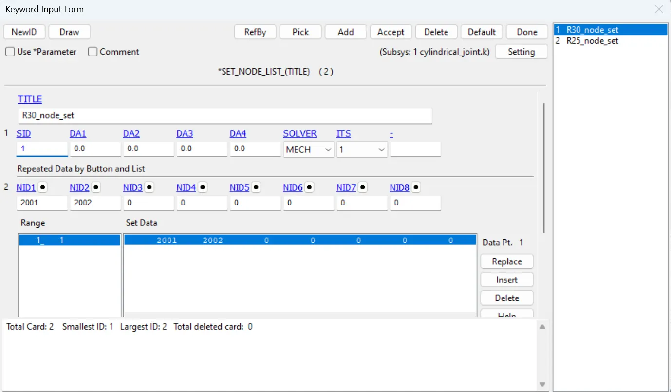

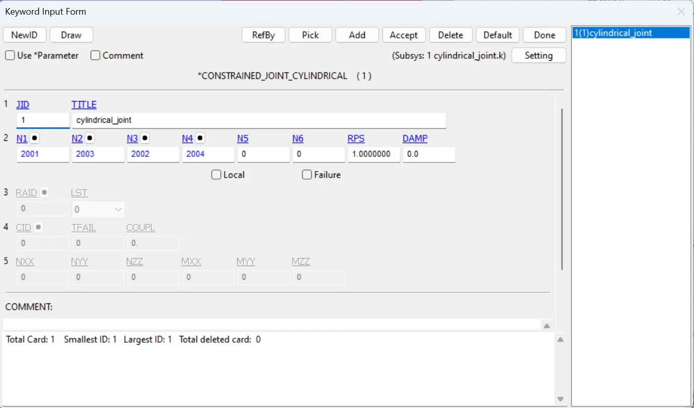
- Use constrained_joint_cylindrical card in Model&keywords> all> constrained, assign the N1,N3 for part 1 and N2, N4 for Part 2.
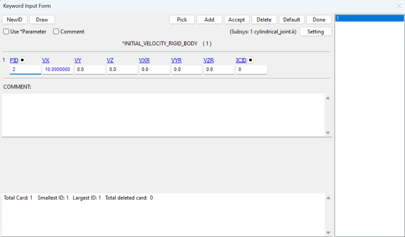
- After creating the joint we need to create the give the initial velocity Rigid bodies for the inside cylinder as vx=10mm/ms.
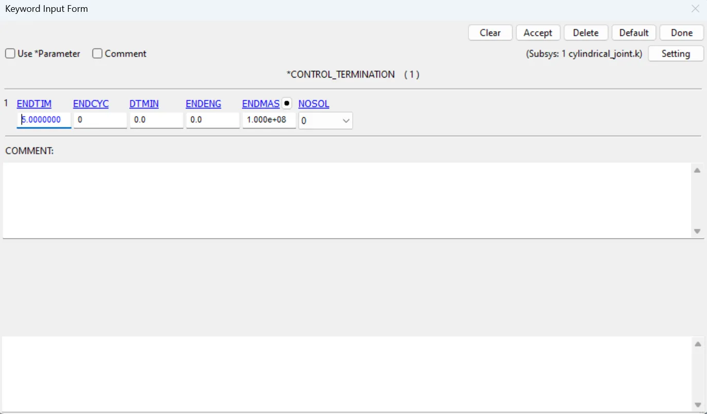
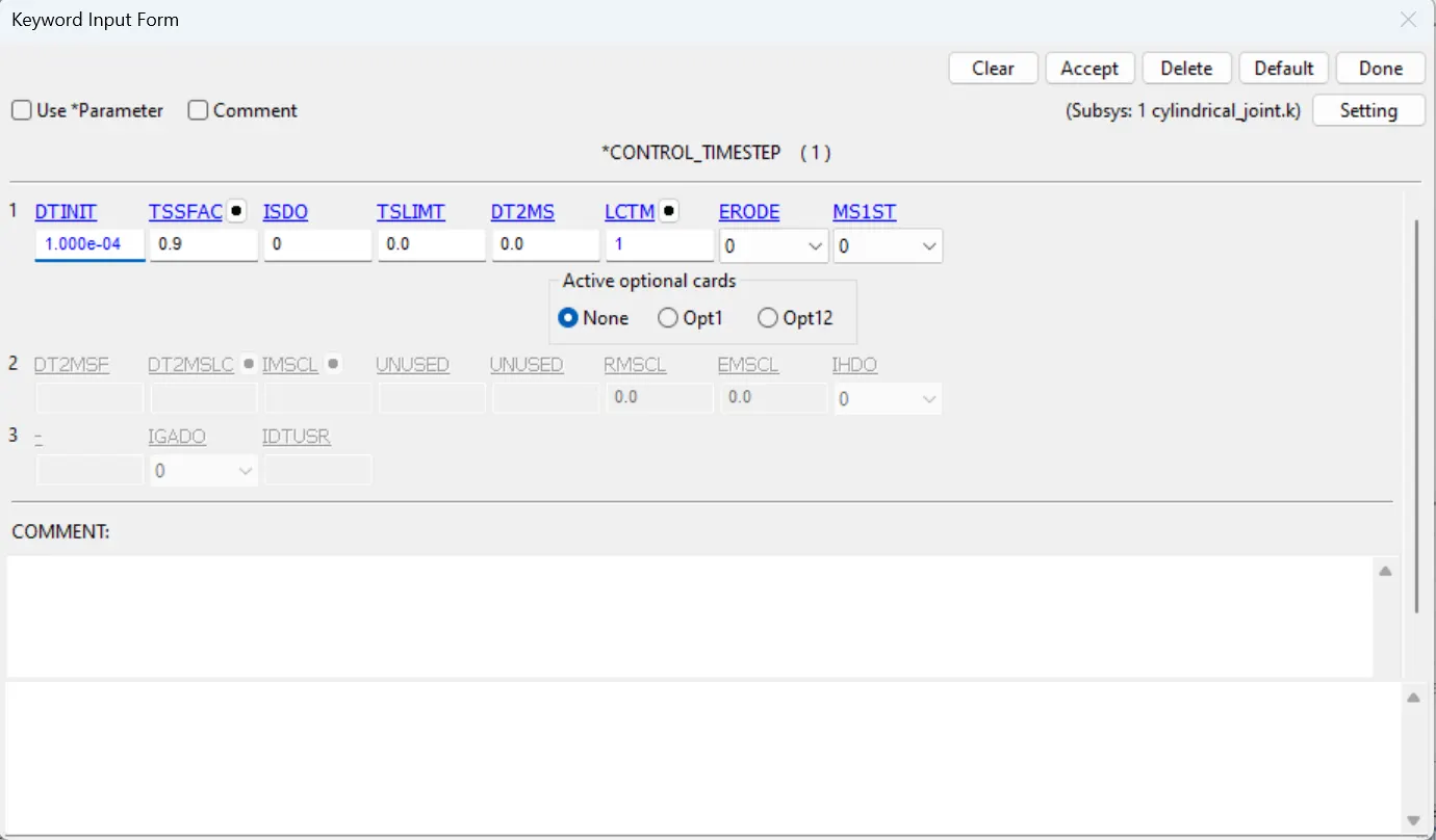
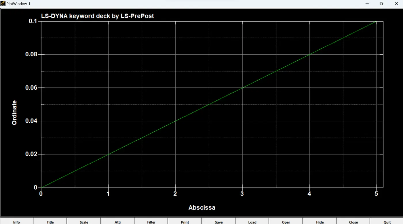
- Lastly we need to create the control termination card with time step with endtime as 5ms and control timestep card to control the time step with the curve as shown in figure.
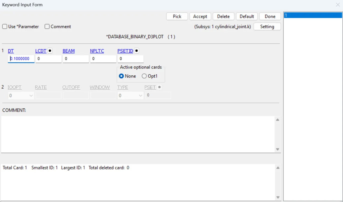
- Give the database d3plot with dt as 0.1 seconds.
CYLINDRICAL JOINT DEFORMABLE:
- Here all the steps are similar except the material is changed from the Mat_Rigid to Mat_Elastic.
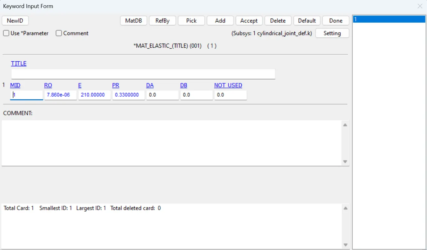
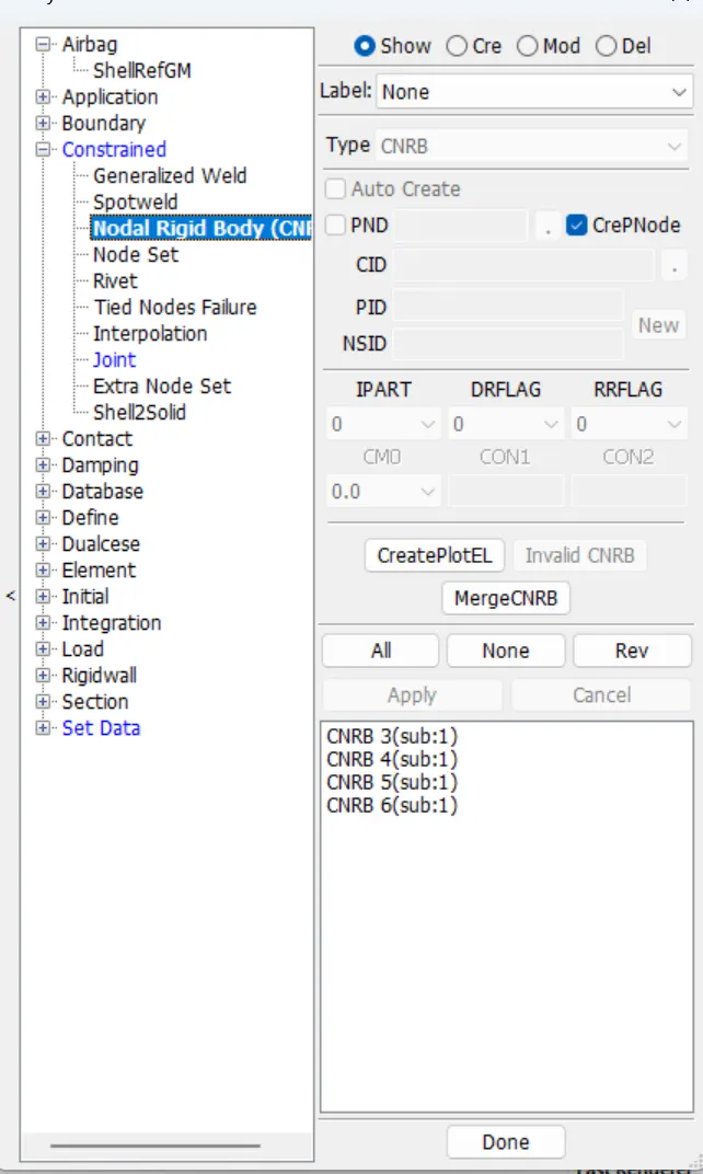
- For the deformable bodies the we need to create the Constrained_Nodal_Rigid_bodies(CNRB) card which is in Model&keywords> create entity> Constarined. First uncheck the Pnode and then select the 2001 node and select the nodes which are nearer to that point repeat the same procedure for the remaining 2002,2003,2004. After creating the CNRBs we need to create the joint using the those 4 nodes.
TRANSLATIONAL JOINT RIGID:
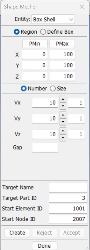
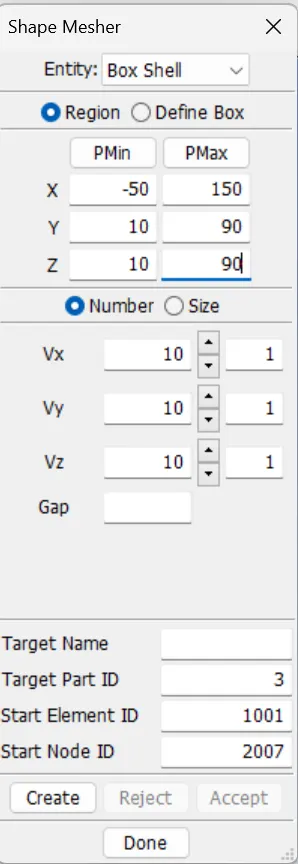
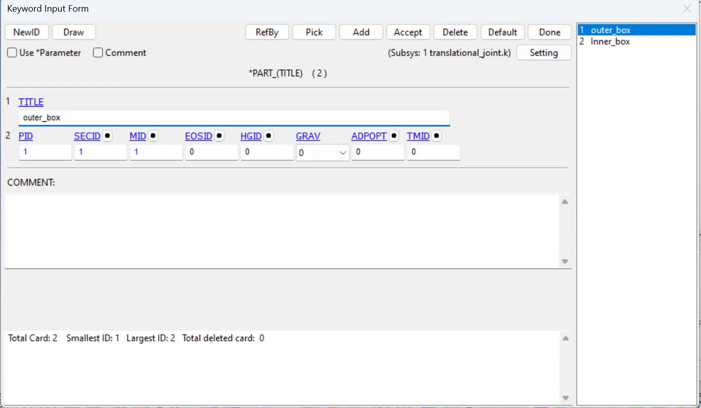
- First using the shape mesher using Elements and tools, create 2 boxes using Box shells.
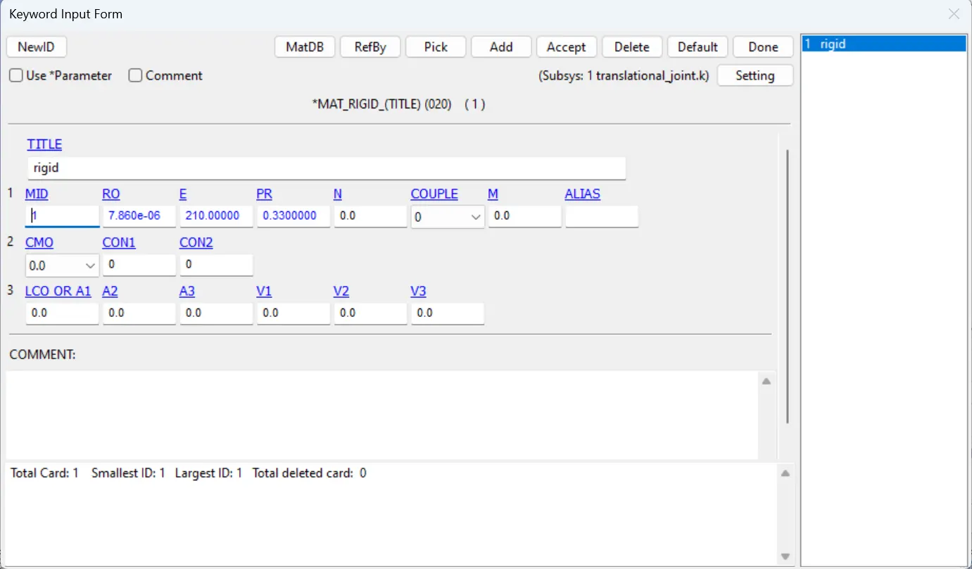
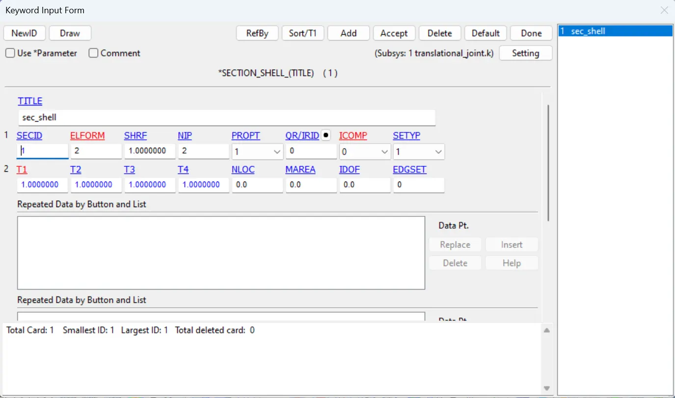
- Then create the Mat_rigid material and Section with thickness 1mm and assign the material and section to their respective parts.
- Using the Elements and Mesh> node editing create the nodes at the center of the 2 boxes, 3 for each cylinder.
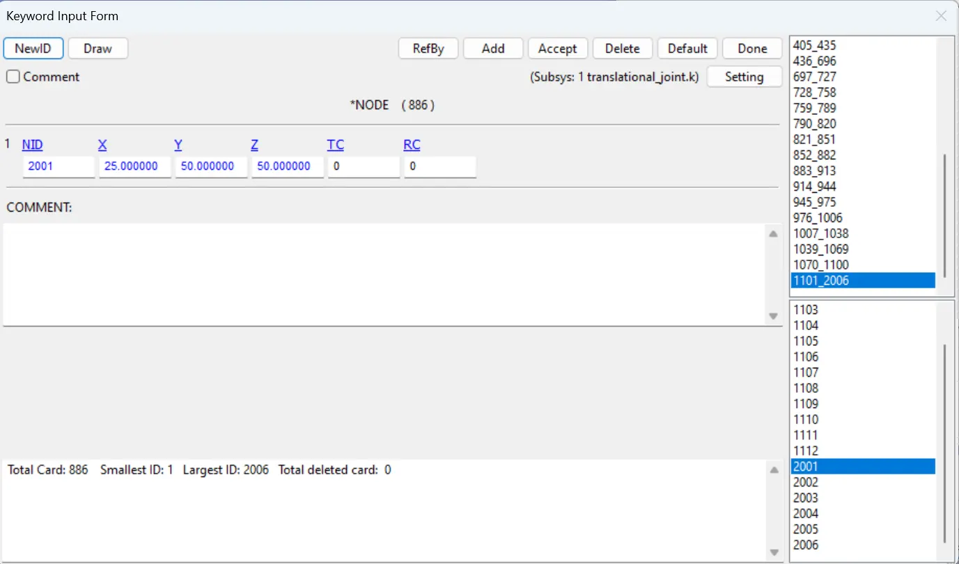
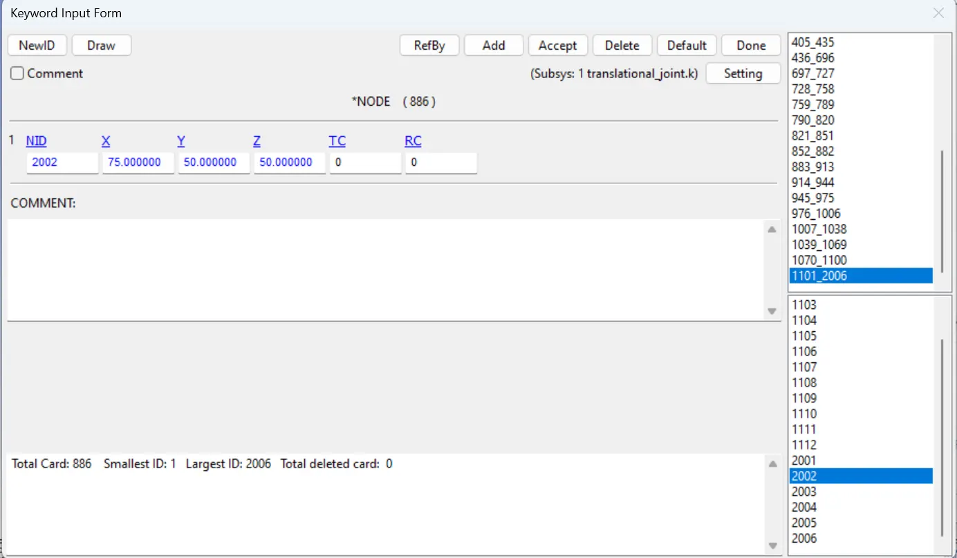
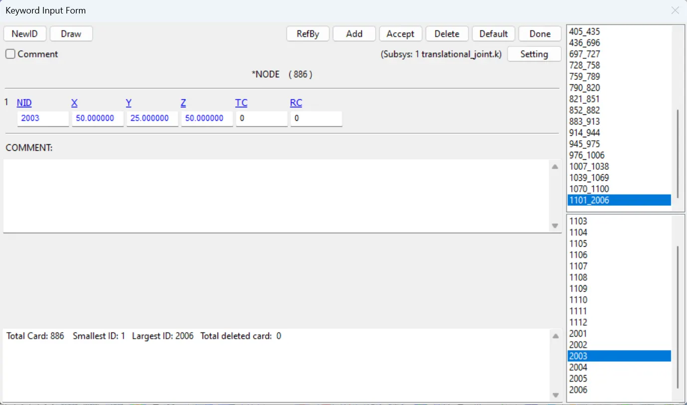
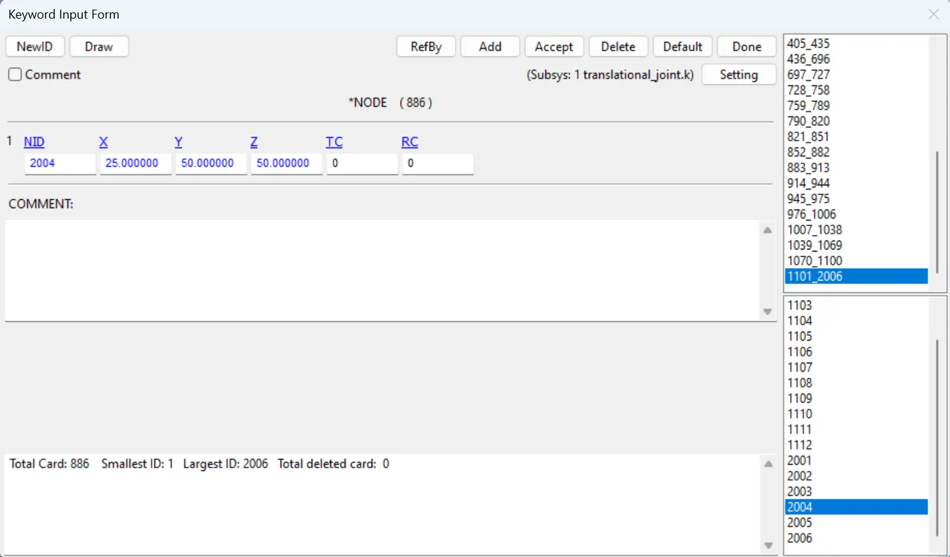
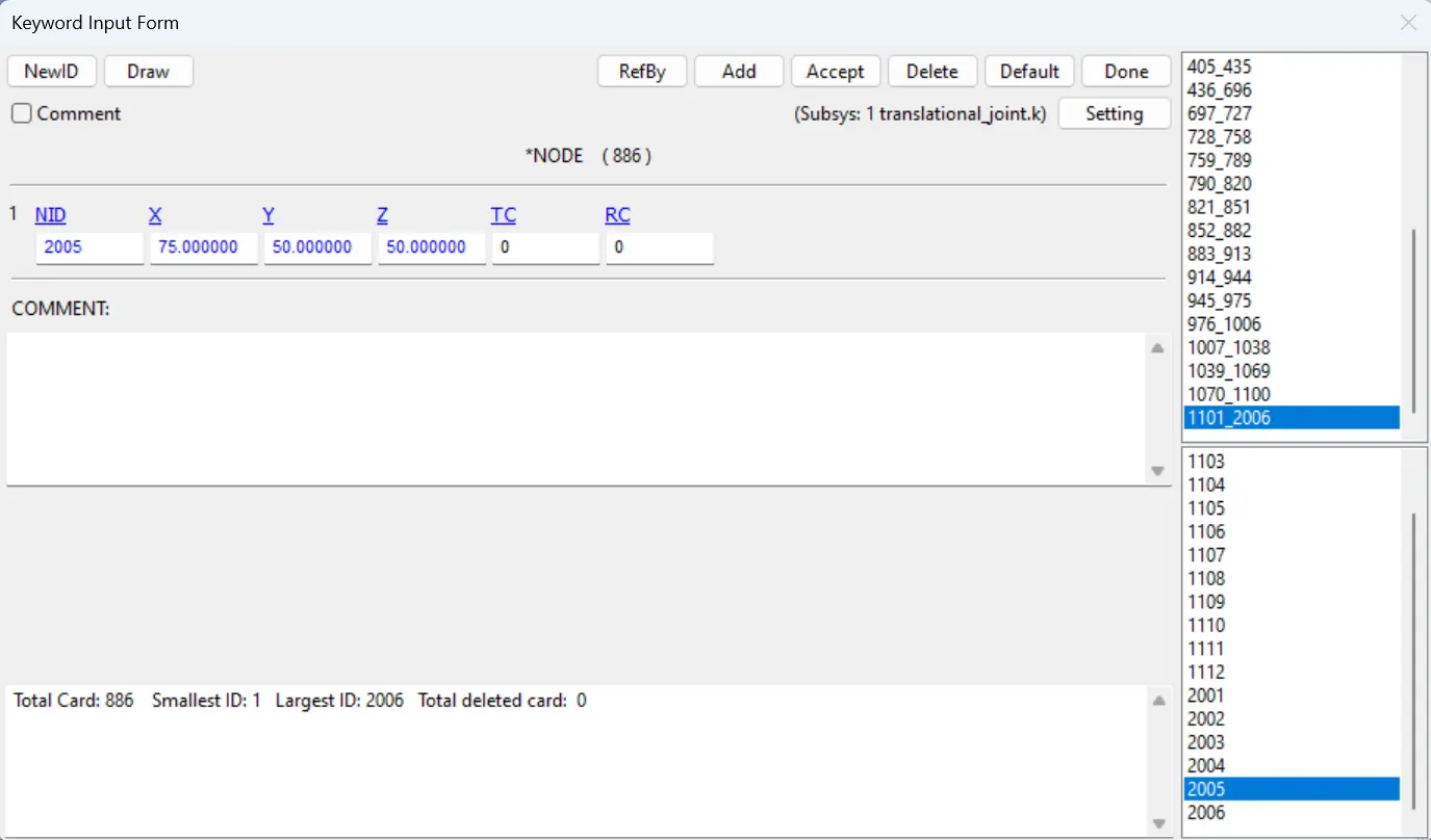
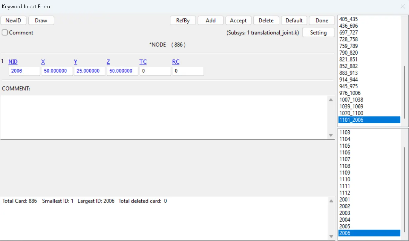
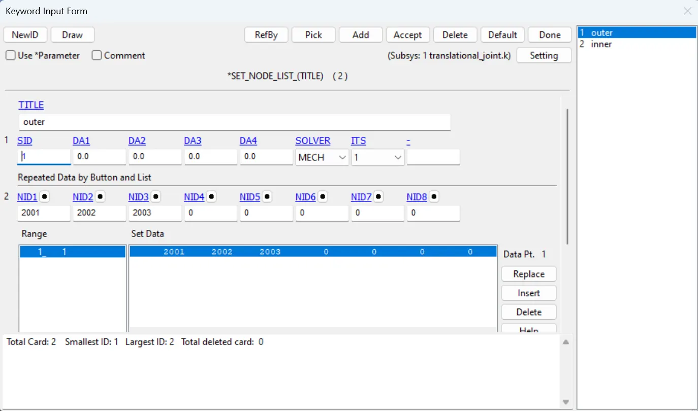
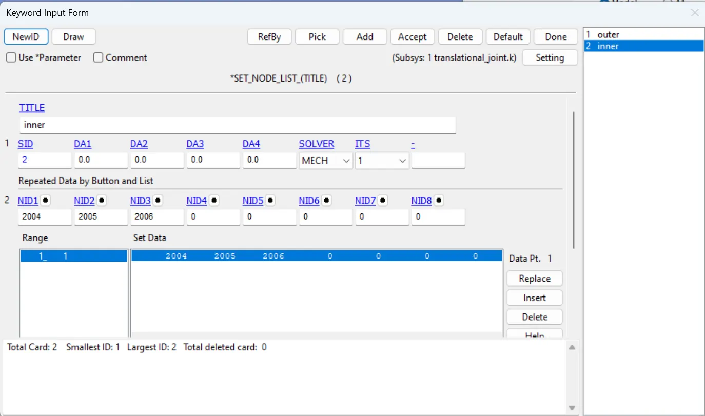
- Create two node sets by using the model & keywords> create entity> set_node using the nodes created above, 2001,2002 and 2003 one node set and 2004,2005 and 2006 second node set.
- Assign the node set1 to part 1 and node set 2 to part 2 using the constrained_extra_nodeset card in model&keywords> all> constrained.
- Use constrained_joint_translational card in Model&keywords> all> constrained, assign the N1,N3,N5 for part 1 and N2, N4, N6 for Part 2.
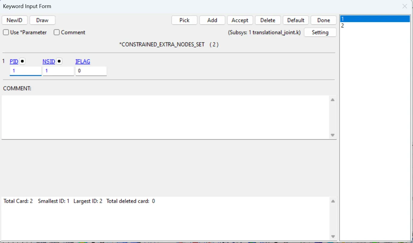
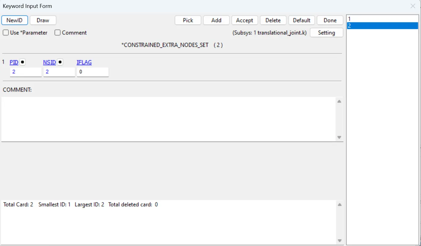
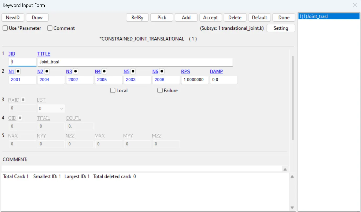
- After creating the joint we need to create the give the initial velocity Rigid bodies for the inside box as vx=10mm/ms.
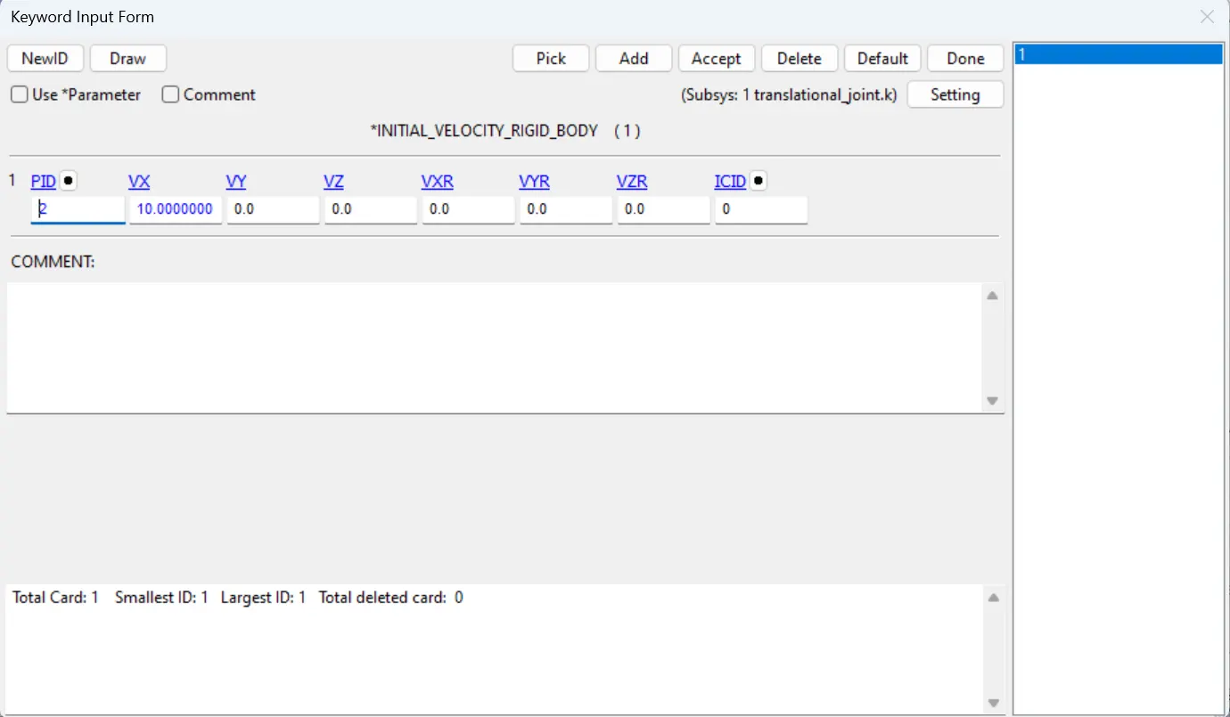
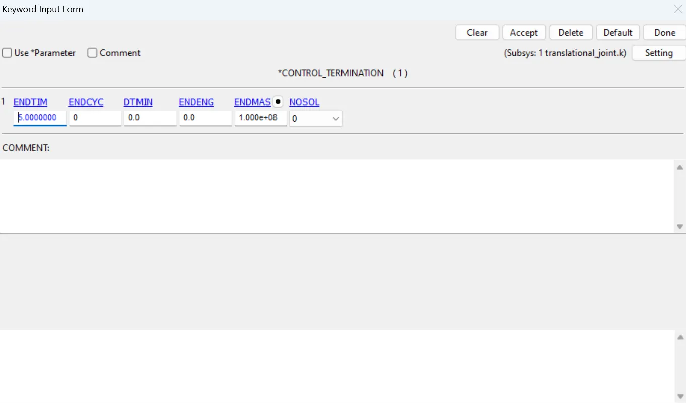
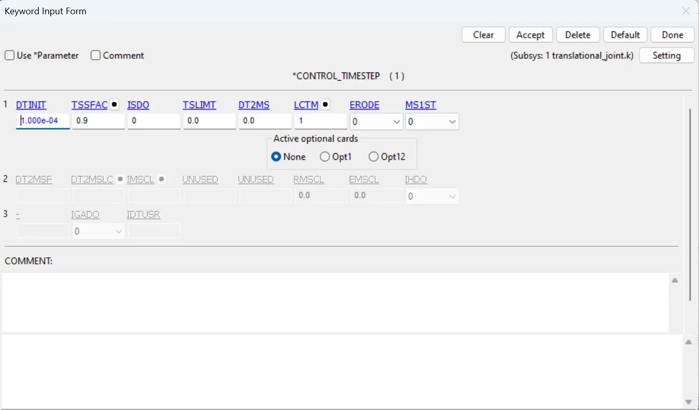
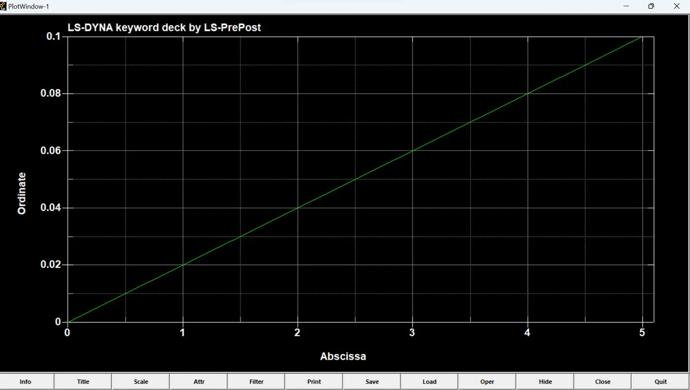
- Lastly we need to create the control termination card with time step with endtime as 5ms and control timestep card to control the time step with the curve as shown in figure.
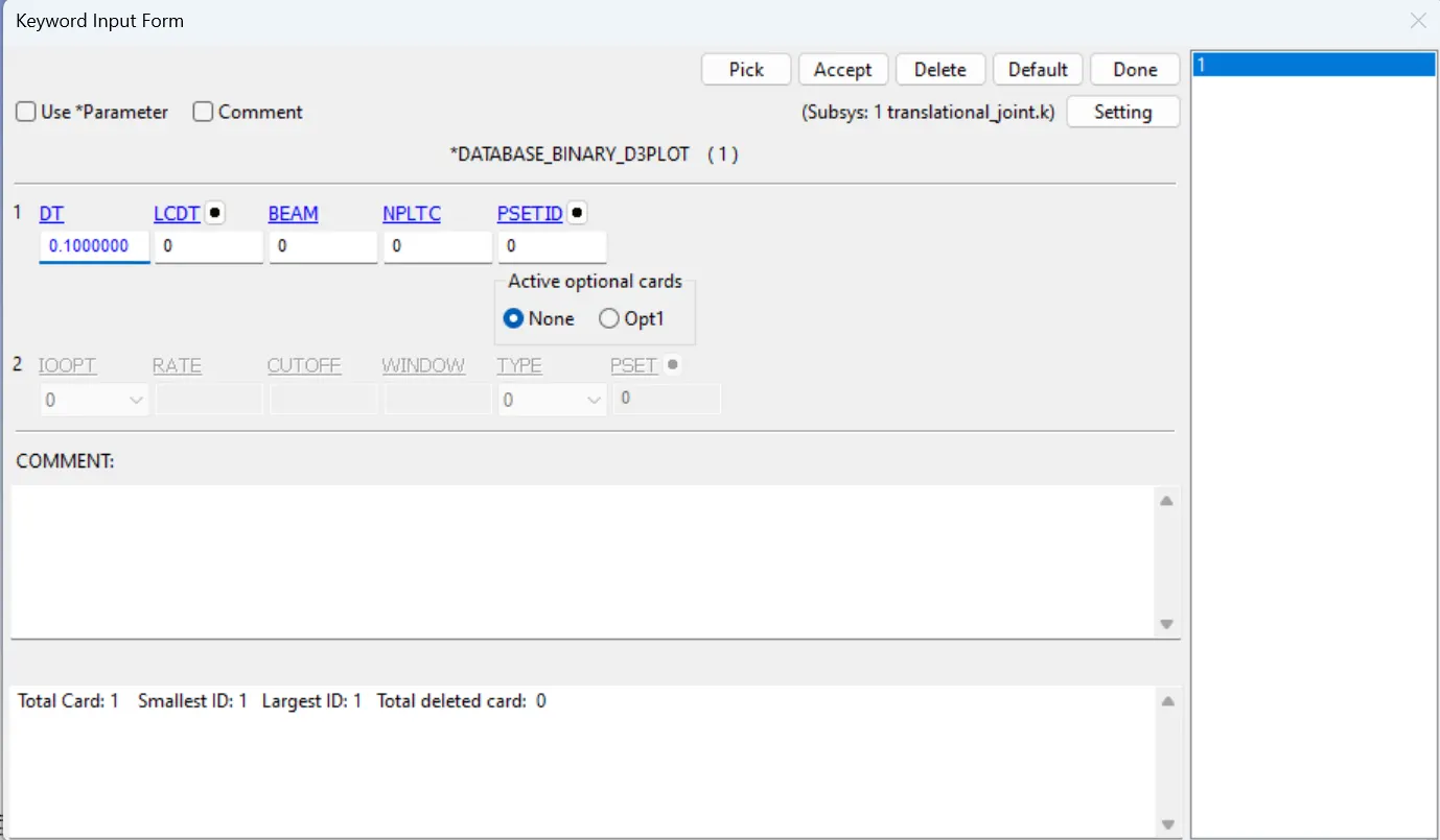
- Give the database d3plot with dt as 0.1 seconds.
CYLINDRICAL JOINT DEFORMABLE:
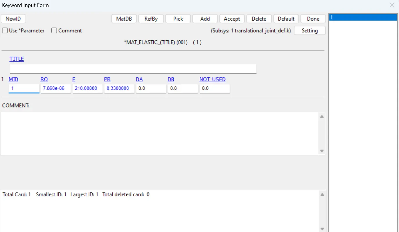
- Here all the steps are similar except the material is changed from the Mat_Rigid to Mat_Elastic.
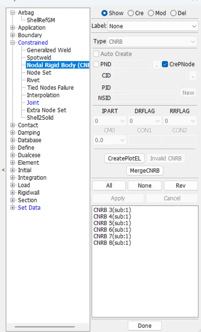
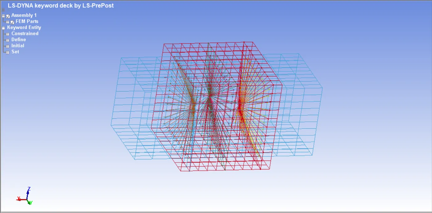
- For the deformable bodies the we need to create the Constrained_Nodal_Rigid_bodies(CNRB) card which is in Model&keywords> create entity> Constarined. First uncheck the Pnode and then select the 2001 node and select the nodes which are nearer to that point repeat the same procedure for the remaining 2002,2003,2004,2005 and 2006. After creating the CNRBs we need to create the joint using the those 4 nodes.
CONCLUSIONS:
- The different joints have been created and simulated using the rigid bodies and deformable bodies in the LS_Dyna.
- The only difference between the rigid and deformable bodies is the using the constrained_extra_nodes for rigid bodies and Constrained_nodal_rigid_bodies for the deformable ones.
- While using the deformable bodies the there is slight deformation on the bodies when the displacement is given.