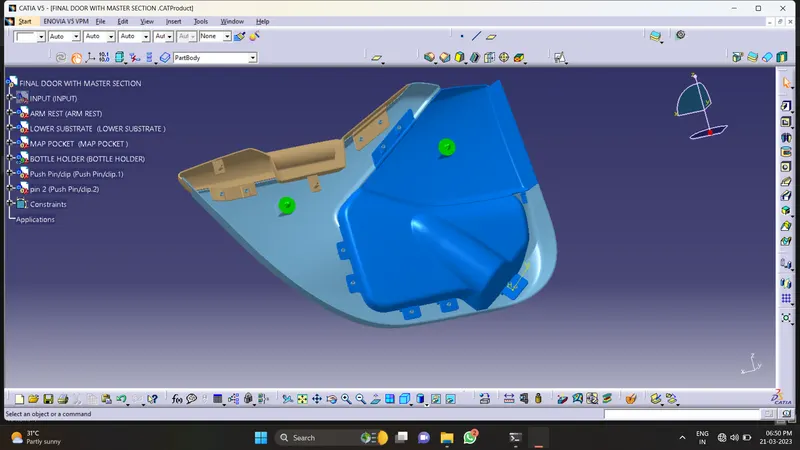
Week 11 - Final project
Development of a Door Trim panel
Objective:
- a) Creation of side door trim panle from given class A surface. Apply thickness to it and use attachment features.
- b) Creation of flanges and heat stakes from given master sections.
- c) Creation of dog house and various attachment features using industry standards.
- d) Performing draft analysis and ensuring the features and surfaces clear it.
There is ten stages in automotive product life cycle developement. In this case our project is step 5 & step 6, that is New Product design and development. The objective is to design class B and class C surface from given class A surface and create a solid body from it using softwares like CATIA V5 taking into consideration the draft analysis which makes the component suitable for production using injection molding process.
Steps:
Given below is the procedure to create a new plastic component from given class A surface .
1) Creation of tooling axis
2) Creation of class b surface
3) Creation of class C surface
4) Creation of closed body
5) Draft Analysis .
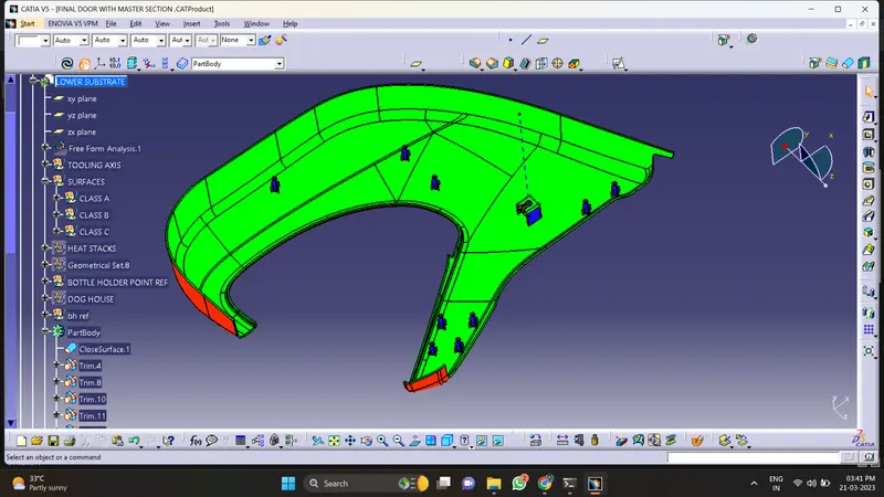
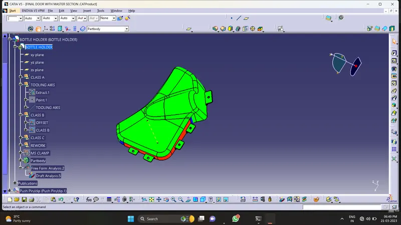
Draft analysis is done to ensure that the designed part is manufacturable based on the draft conditions applied. It is done to ensure the proper ejection of the component from dies(for metals) or molds(for plastics). The basic idea is to ensure that the tooling axis has to be created in such a wat that it has no parallel surface profiles of the component so that the ejection of the components can be ensured . Tooling axis is the axis along which cavity and core are closed and opened .
The main components of interior door panel of a car consists of the following parts .
1) Arm rest
2) Map pocket (Consists of upper and lower part)
3) Upper substrate (Not given in the current model)
4) Lower substrate .
Armrest-
Designers of plastic parts and mould tooling manufacturers can use the Draft Analysis tool to check the correct application of draft to the faces of their part. With draft analysis, you can verify draft angles, examine angle changes within a face, as well as locate parting lines, injection, and ejection surfaces in parts.
For this case as no hole is concerned, so we will try to consider the perpendicular axis of that dented curved surface, for creating the tooling axis. So we will analyse perpendicular plane.
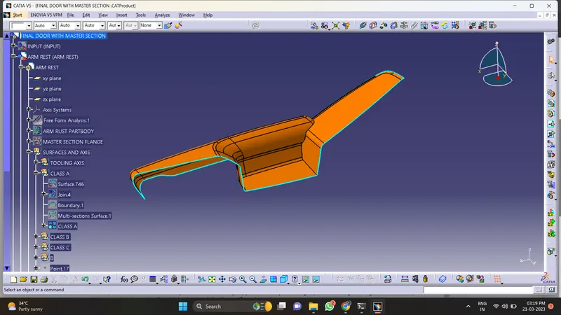
you can creat class b surface offset and check bondarys
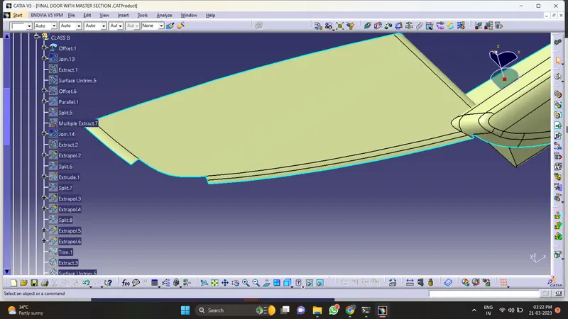
then correct b surface
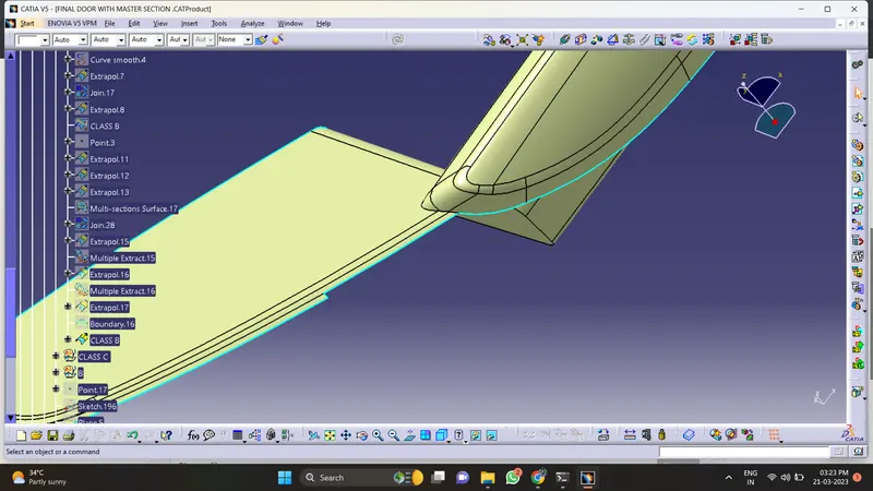
then creating c surface
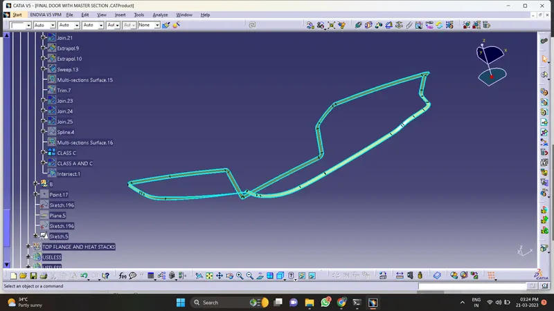
now join a and c surface for triming with b surface
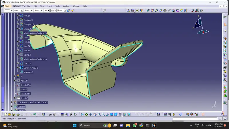
after you need to trim both surface
then you get a final trim part
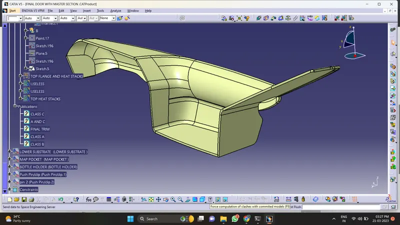
now change into part design and make a close srface body
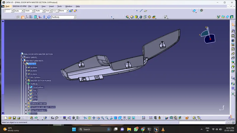
check the draft analysis
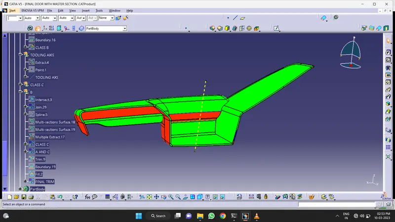
then creating engineering features
like
1.heat stacks
2.flange
3.locater
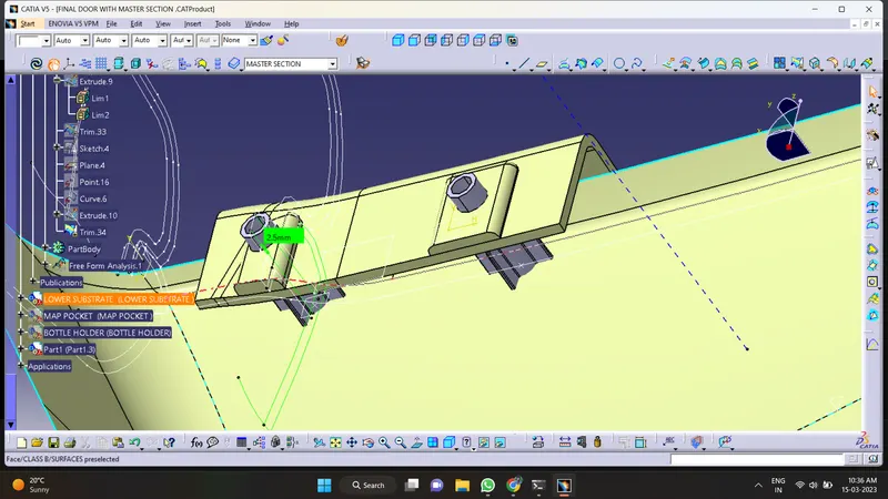
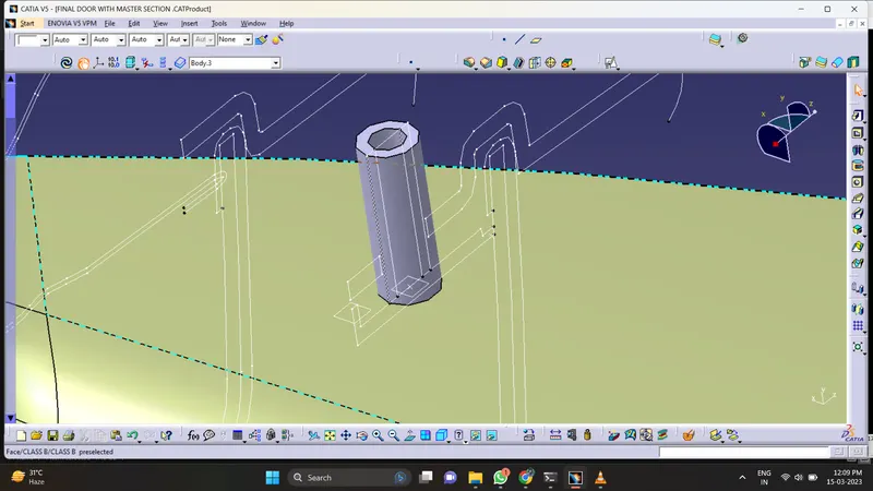
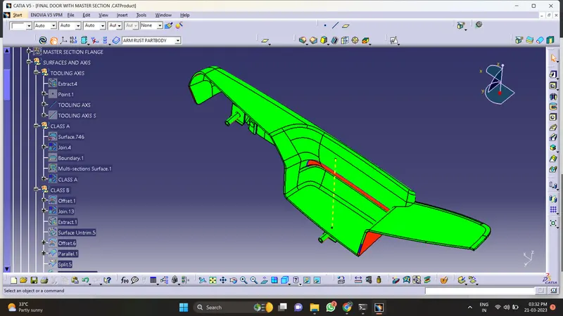
Lower Substrait -
open a surface and check boundray
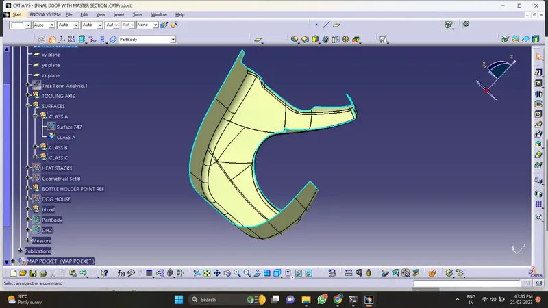
creat tooling axis
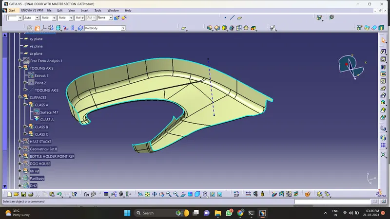
creat b surface
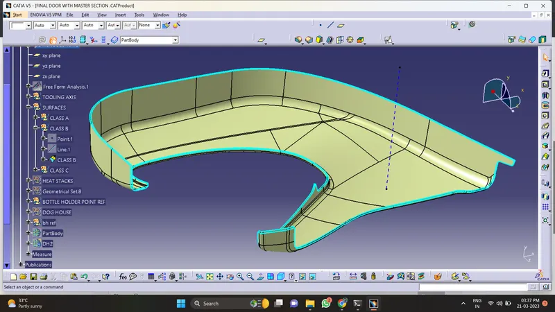
then creat c surface
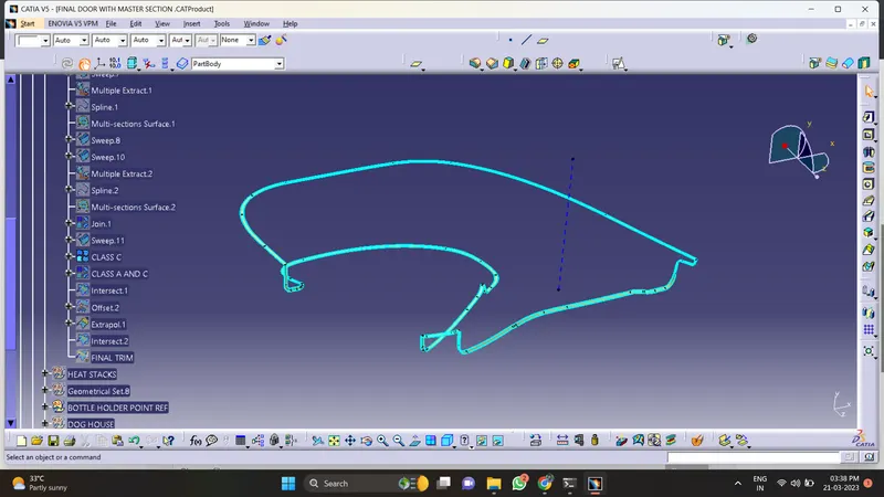
join a and c
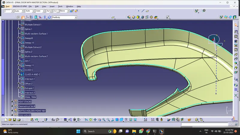
then trim with b surface
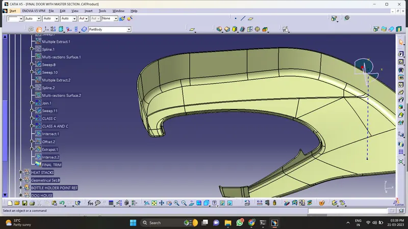
now you can creat close surface
and can creat engineering feature like
1.heat stacks
2.dog house
3.flanges
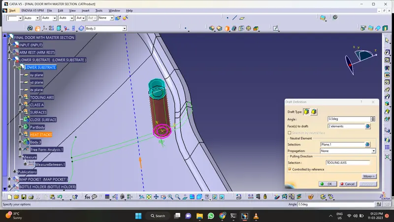
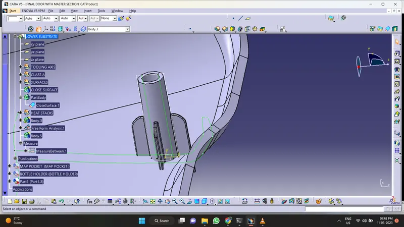
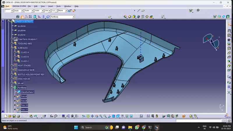
cheack with draft analysis
Upper Map Pocket
open class a surface
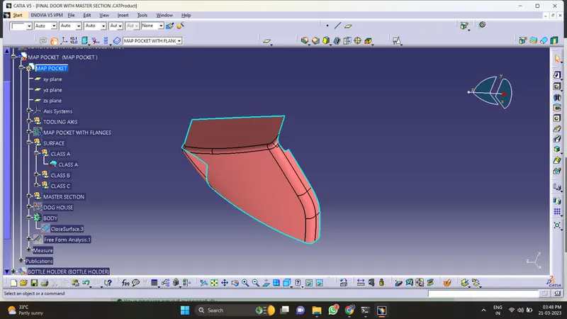
creating tooling axis
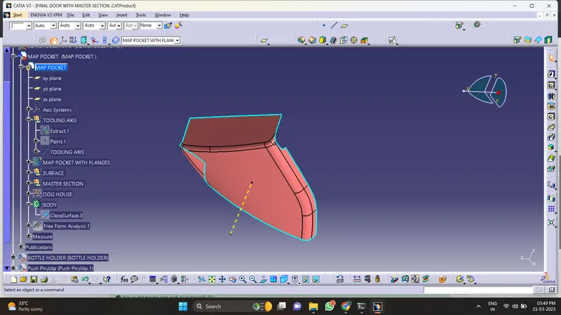
then offset from a now you need ot modify
class b
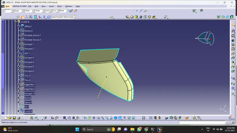
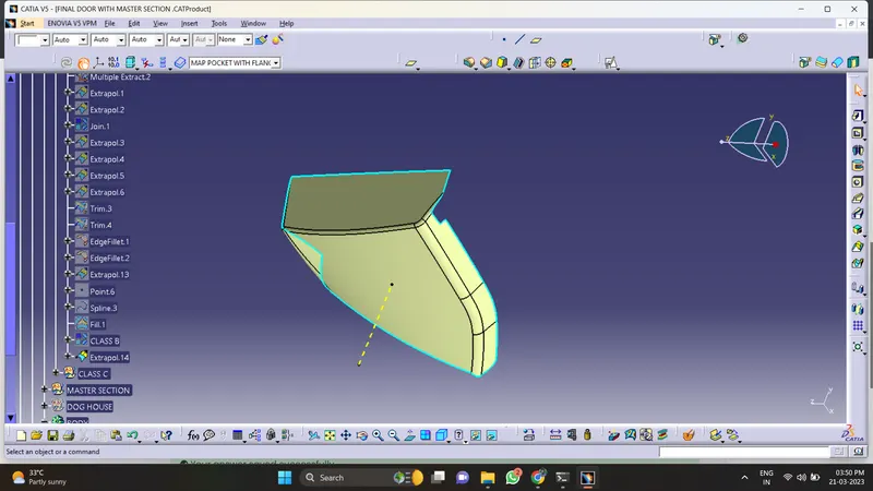
creat c surface from referance a
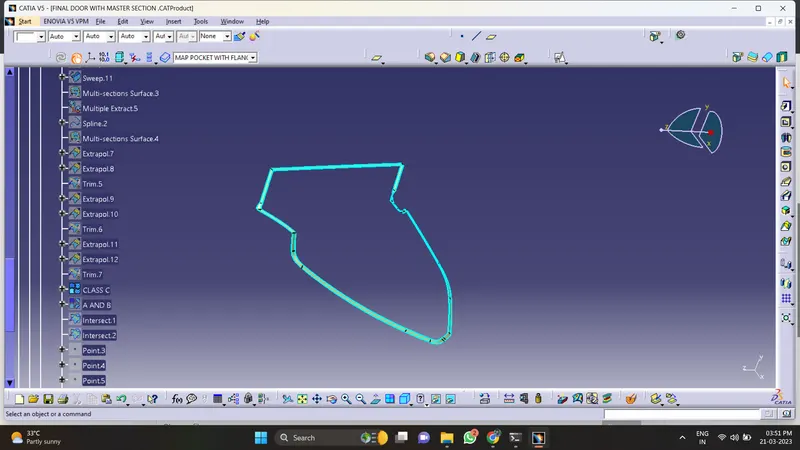
join class a and c surface
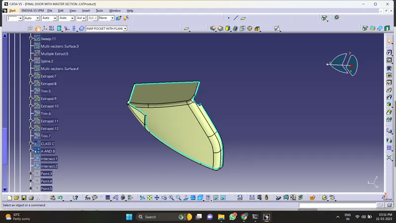
trim with b surface
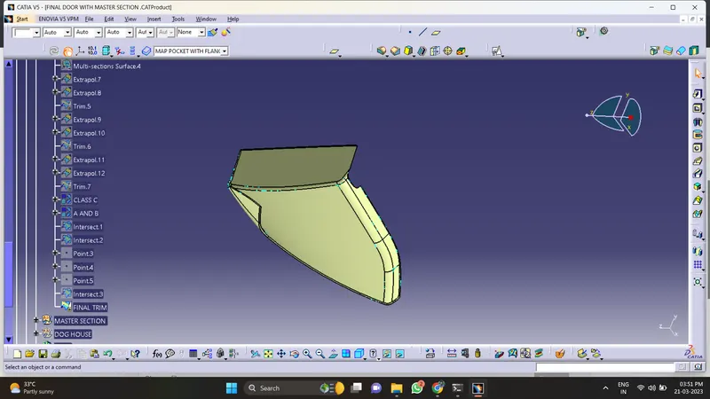
now make close surface
then creat engineering feature
1.flanges
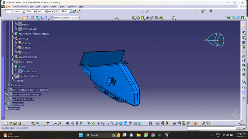
check draft analysis
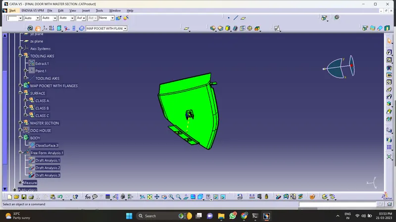
Lower Map Pocket
open class a surface
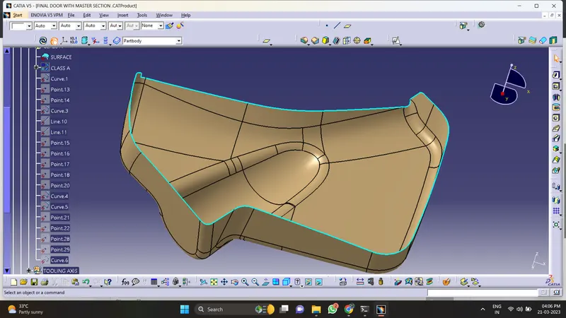
creat tooling axis
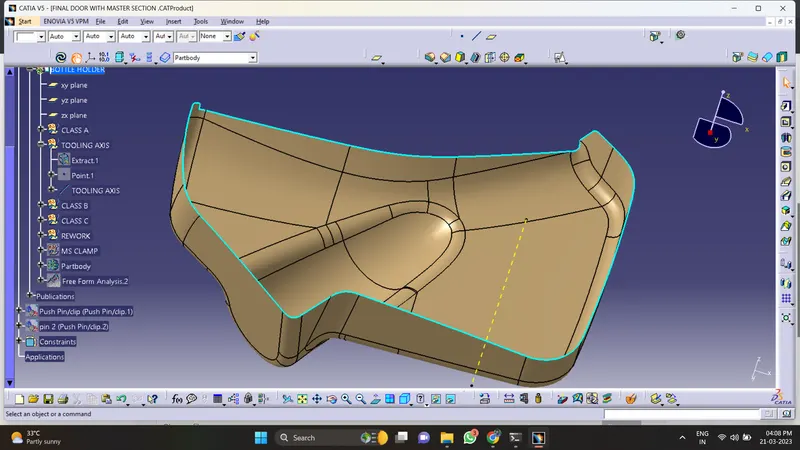
creating class b surface
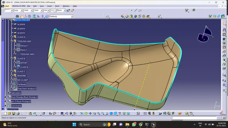
then creat class c surface
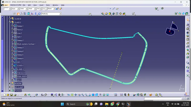
join a and c surface
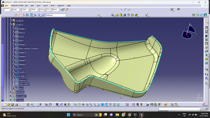
creat close surface
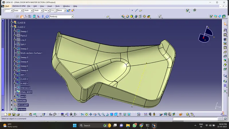
make close body
creat engineering feature
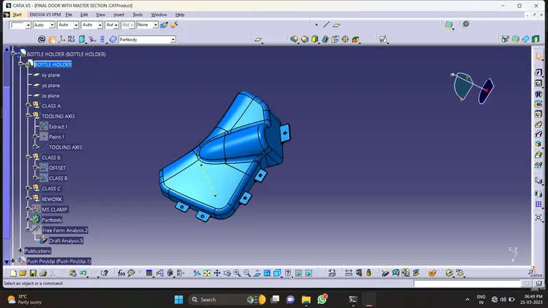
cheack draft analysis
now assemble push pin