Week 11 - Final project
FINAL PROJECT– DOOR TRIM
OBJECTIVES:
- To create individual tooling axis for the parts and perform draft analysis on the class A surface
- To create the class B and class C surfaces from the given class A surface
- To form a solid geometry by combining all the surfaces
- To decide an attachment strategy for the part and create engineering features in reference from the master section provided
- To perform draft analysis on the solid part model with all engineering features
- To assemble all the components togehter to obtain the final trim
INTRODUCTION:
Next to the dashboard, the door trims are the interior parts that contain most of the controls and decorative parts the door trim comprises of various components such as the arm rest, map pocket, switch bezel, speaker and other electronic regulators and aesthetic trims designed in a way to enhance the user experience of the driver and the passenger.
The plastic trim is attached to the sheet metal component which is the door inner with the help of various engineering features such as push clips, heat stakes etc.
METHODOLOGY:
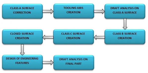
LOWER SUBSTRATE
PRE-DESIGN CHECKS:
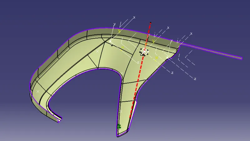
Before starting the creation of the class B surface we must ensure that the given class A surface is properly closed and the surface continuity is proper. This can be done either with the help of the join operation or by using the boundary feature.
The surface received had a closed boundary but contained an extra surface extending as shown in the image which had to be trimmed in reference with the other parts.
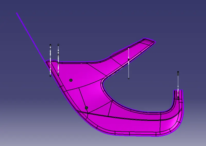
Fig: Class A of Lower Substrate
TOOLING AXIS:
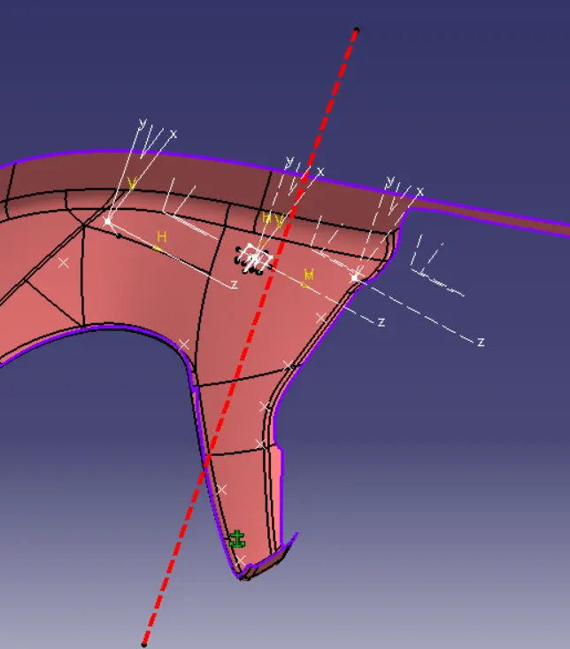
- The next step is to create the tooling axis for the part which will determine the direction in which the core and cavity of the mould will move.
- Designer must ensure that all holes and slots are covered in the main tooling and thus side core must be avoided whenever possible
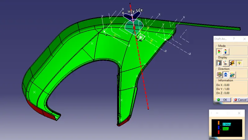
- After analysing visually for the best possible tooling axis, an axis system is created on the centre of one of the surfaces of the lower substrate.
- First a dummy tooling axis is drawn along the Y direction with the axis system and the centre point as reference
- If the draft analysis is cleared with the dummy tooling axis then it is considered as our main tooling axis if not then the tooling axis is created with the help of bisecting method
DRAFT ANALYSIS:
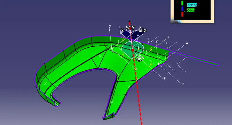
- Draft analysis is done on the class a surface after the tooling axis has been obtained
- The part must have a minimum draft angle of 3 degrees on all the tapered faces
- Using the feature draft analysis tool and the compass the part surface is validated for the minimum draft criteria
- It is very important to validate the tooling axis for the class A surface since it will be helpful in creating the class C surface
CLASS B SURFACE:
- After all the validation has been done, the class B surface is created by offsetting the class B surface to a distance of 2.5 mm
- After offsetting many openings in the surfaces are found which are closed with the help of multi sections-surface and sweep commands.
- The class B surface is then extrapolated in parts to trim it along with the class C surface
CLASS C SURFACE:
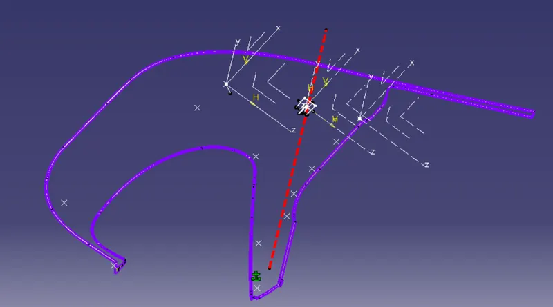
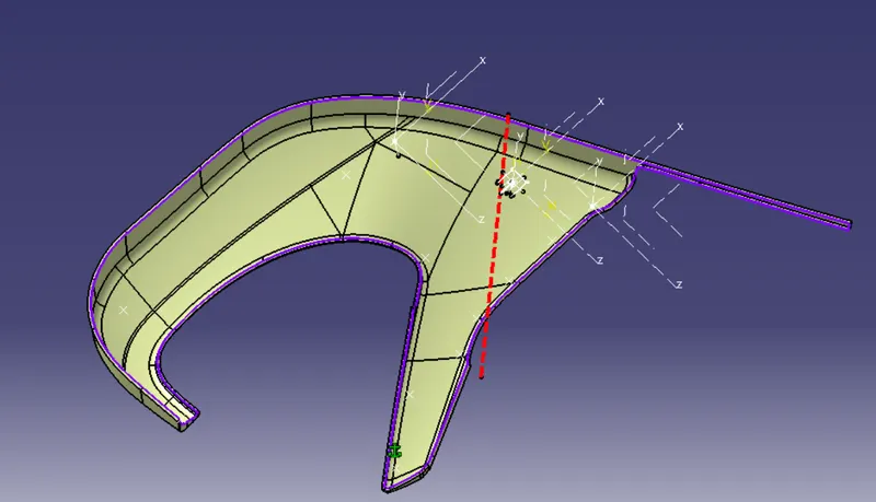
- The class C surface which connects the class A and class B surface is created by sweeping the boundary of the class A and using the class A as a reference.
- The sweep is divided into several parts in order to avoid complexity
- Surfaces which are parallel to the tooling direction are swept with the tooling axis as reference and with a draft angle of 3 degrees
PART:
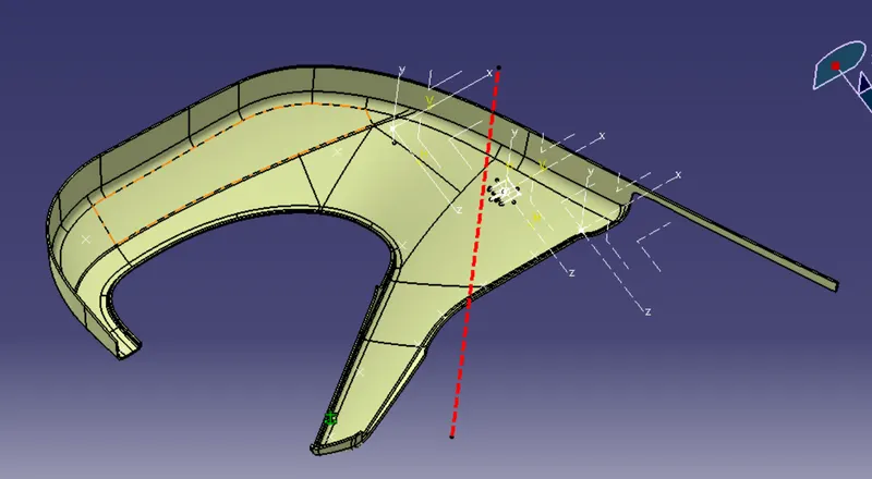
The final trim is created by joining the Class A and C surface and finally trimming it with the Class B surface. The combination of class A, B and C surface is then converted into a solid with the aid of fill command in the part workbench
ENGINEERING FEATURES:
DOG HOUSE:
- The two main purposes of a dog house are to avoid sink marks and to house various other engineering features like screw boss, locators, push clips etc.
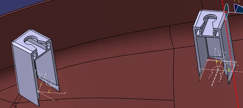
- In this case, the dog house is designed to house the push clips and the 4 way locator. The dog house designed for the push clip features a slot on the top face to accommodate the push clip
- The dog house should follow certain design rules which are stated below
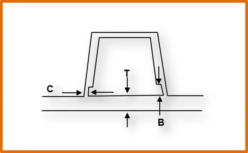
Figure 1.7 Design rules of dog house
- Doghouse wall thickness at the intersection of the part wall (C) should be 40% or less than the main wall stock (T).
- The height of ( B ) should be between 3.0 – 6.0 mm
- Outer surface of dog house must have a draft angle of 3 degrees
- Inner surface of dog house must have a draft angle of 0.5 degrees
HEAT STAKE:
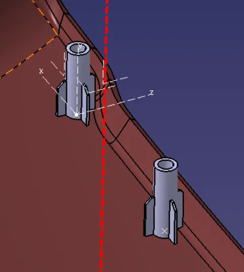
- Heat stakes are used in thermoplastics to assemble two parts together by locally heating and cooling the plastic material and allowing it to reform itself and act as a joint for the two materials.
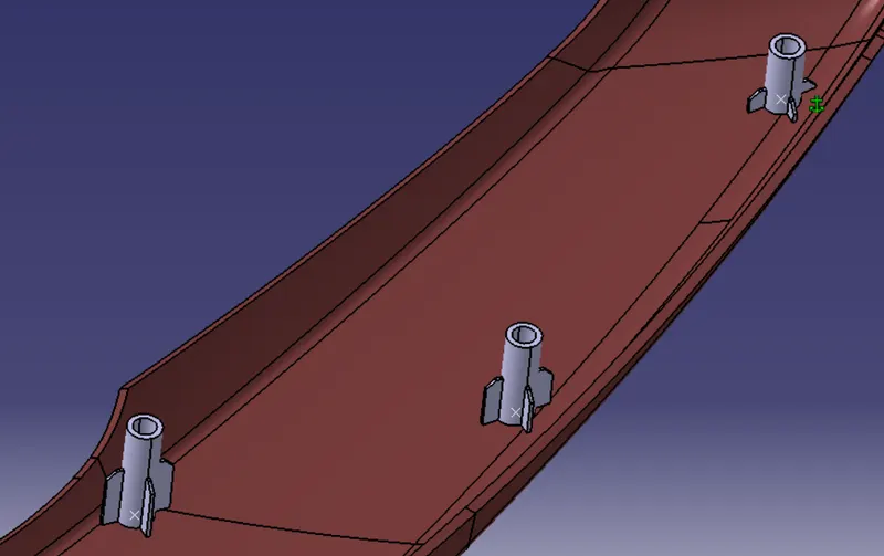
- We have placed 9 heat stakes in the model based on the reference points created by estimation.
- One of the important factor to be considered while designing the heat skates is the height of the heat skates. It should always be less than the height of the locators
LOCATOR:
- The main purpose of locators is to facilitate proper locking of two components together while assembling and arrest the maximum degrees of freedom possible.
- These locators are similar to guide pins provided in mould.
- The two types of locators used are two way locator and four way locator.
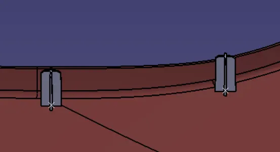
- We have positioned three 4 way locators in our model which meet the rib design criteria.
- Loctors which where violating the height rule were placed on a dog house to avoid any defects while manufacturing and also possible failures during assmebly.
RIB:
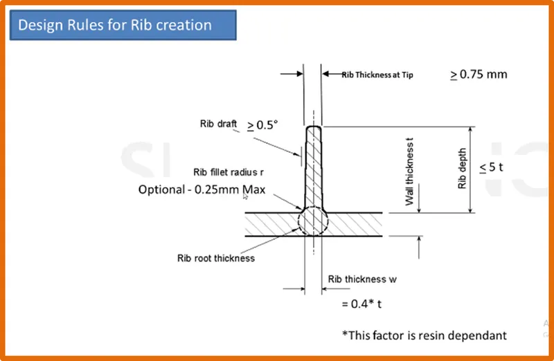
The main purpose of rib is to increase the stifffness of the part in certain critical areas without adding much weight and complexity to the component
ARM REST:
PRE-DESIGN CHECKS:
The class A surface of the arm rest received had a small opening near the edges as shown below. Join operation was used to close the opening in the surface
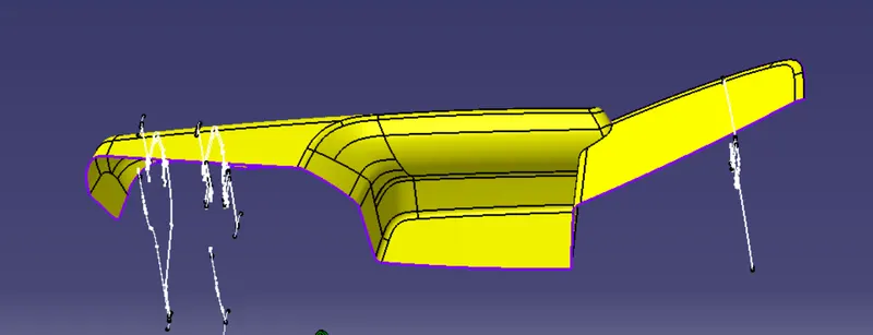
Fig: Class A of Arm Rest
TOOLING AXIS:
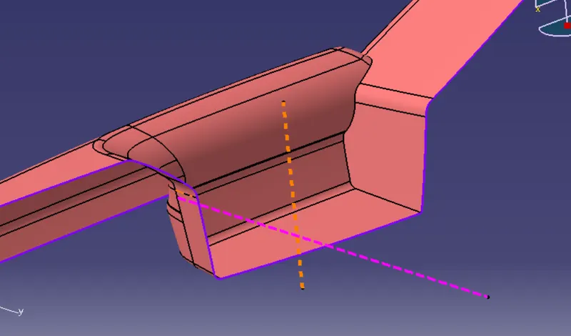
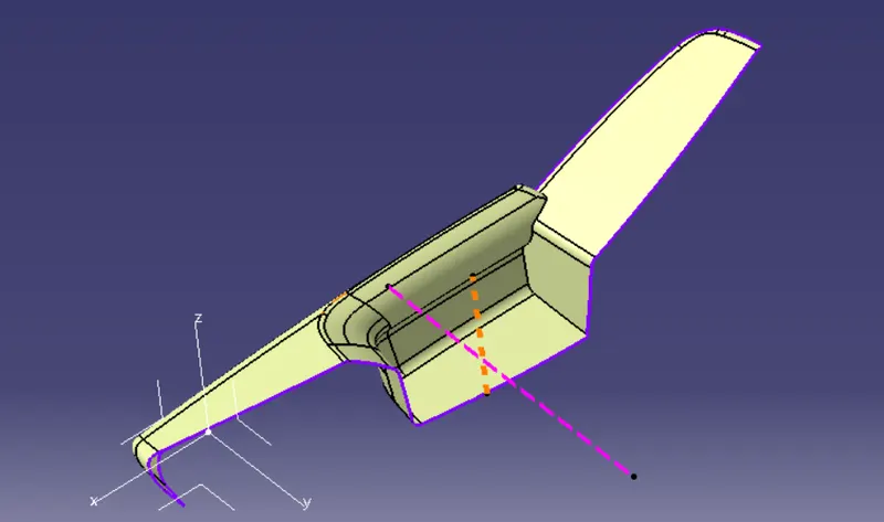
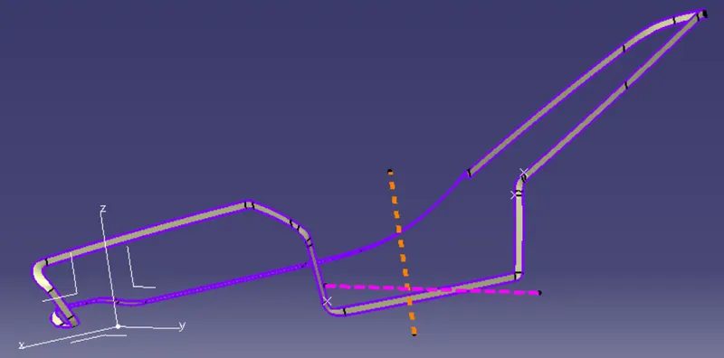
Due to complexity of the surface was impossible to clear all the surfaces in a single tooling axis and hence two tooling axis where created as below
DRAFT ANALYSIS ON PART:
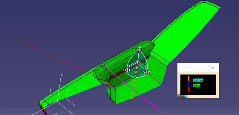
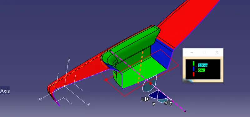
- Draft analysis is done on the final part with the tooling axis as reference
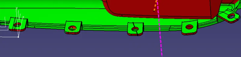
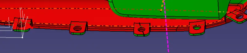
- Green surface indicates the areas where the draft is more than 0.5 degrees.
- Red surface indicates the areas having negative draft.
- All the engineering features are given a draft with reference to the tooling axis and hence they can be cleared in the main tooling
- Lifter axis for clearing the dog house inner surfaces are provided for each individual dog house
CLASS B SURFACE:
- After all the validation has been done, the class B surface is created by offsetting the class B surface to a distance of 2.5 mm
- After offsetting many openings in the surfaces are found which are closed with the help of multi sections-surface and sweep commands.
- The class B surface is then extrapolated in parts to trim it along with the class C surface
CLASS C SURFACE:
- The class C surface which connects the class A and class B surface is created by sweeping the boundary of the class A and using the class A as a reference.
- The sweep is divided into several parts in order to avoid complexity
- Surfaces which are parallel to the tooling direction are swept with the tooling axis as reference and with a draft angle of 3 degrees
PART:
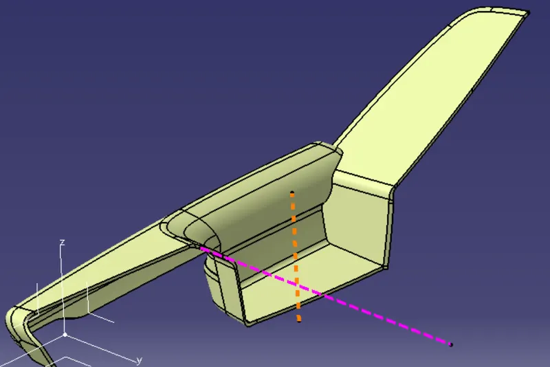
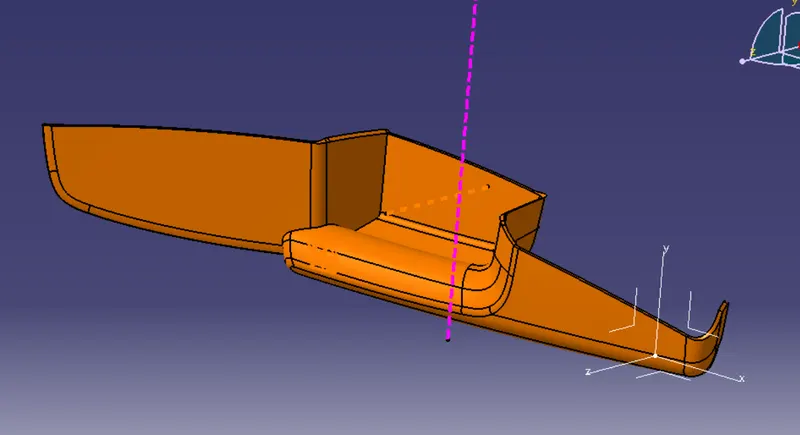
The final trim is created by joining the Class A and C surface and finally trimming it with the Class B surface. The combination of class A, B and C surface is then converted into a solid with the aid of fill command in the part workbench
ENGINEERING FEATURES:
FLANGE:
Flanges were created on the arm rest with the reference dimensions from the master sketch provided. The purpose of the flange was to provide slots for the heat stakes and locator which are required to assemble the two components together and constraint the motion between them
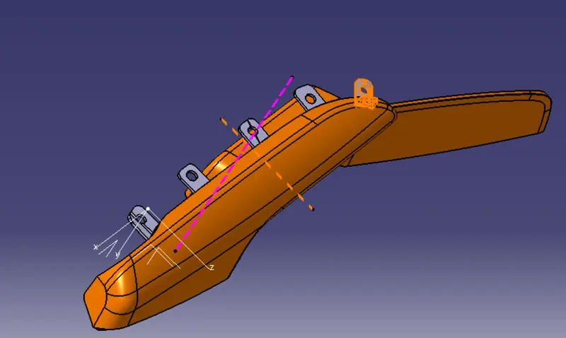
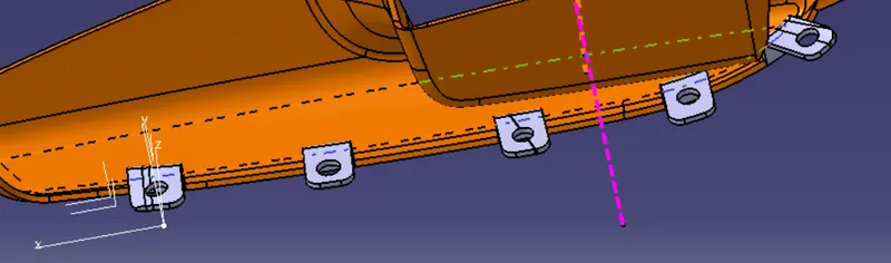
Flanges were creted along the surface of the map pocket bottom holder. The purpose of the flange was to provide slots for the heat stakes and locator which are required to assemble the two components together and constraint the motion between them
DRAFT ANALYSIS ON PART:
- Draft analysis on the final part was done with reference to the main tooling axis
- All the surfaces of the part model seem to clear the minimum draft requirement of 0.5 degrees
MAP POCKET UPPER
PRE-DESIGN CHECKS:
The class A surface provided for the map pocket bottle holder was checked for openings with the aid of boundary feature. There were no openings found in the class A surface and hence the same surface was used in future operations
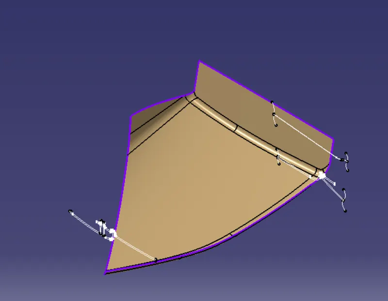
Fig: Class A of Map Pocket
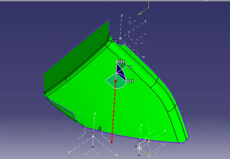
TOOLING AXIS:
- First a dummy tooling axis is drawn along the Y direction with the axis system and the centre point as reference
- If the draft analysis is cleared with the dummy tooling axis then it is considered as our main tooling axis if not then the tooling axis is created with the help of bisecting method.In our case the dummy tooling axis was able to cover all the faces wiht the required draft angle and hence was taken as the main tooling axis
CLASS B SURFACE:
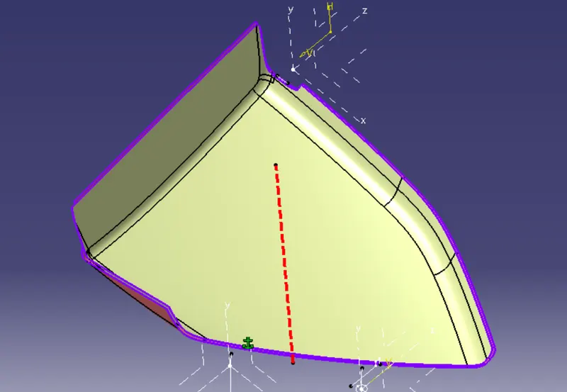
- After all the validation has been done, the class B surface is created by offsetting the class B surface to a distance of 2.5 mm
- After offsetting many openings in the surfaces are found which are closed with the help of multi sections-surface and sweep commands.
- The class B surface is then extrapolated in parts to trim it along with the class C surface
CLASS C SURFACE:
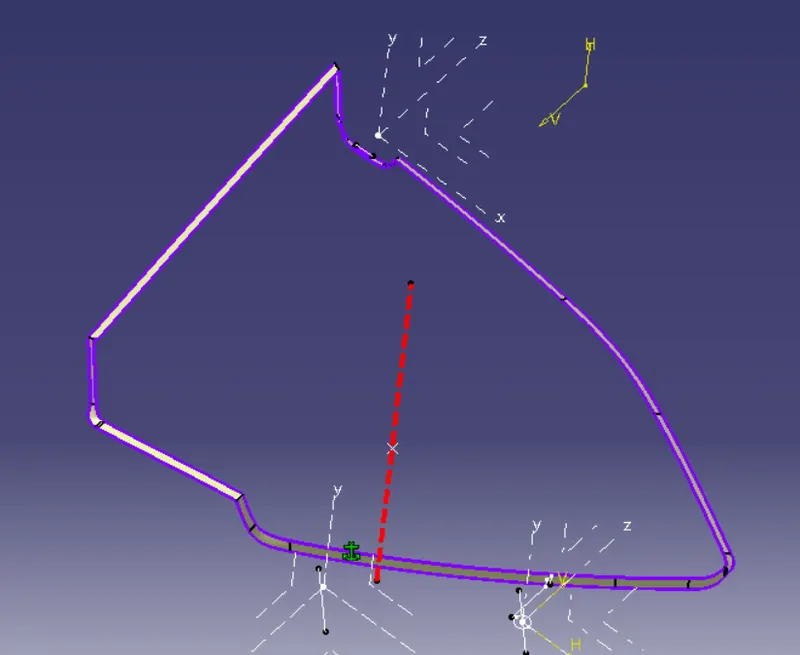
- The class C surface which connects the class A and class B surface is created by sweeping the boundary of the class A and using the class A as a reference.
- The sweep is divided into several parts in order to avoid complexity
- Surfaces which are parallel to the tooling direction are swept with the tooling axis as reference and with a draft angle of 3 degrees
PART:
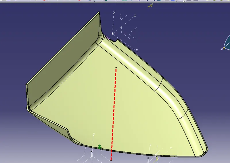
The final trim is created by joining the Class A and C surface and finally trimming it with the Class B surface. The combination of class A, B and C surface is then converted into a solid with the aid of fill command in the part workbench
ENGINEERING FEATURES:
FLANGE:
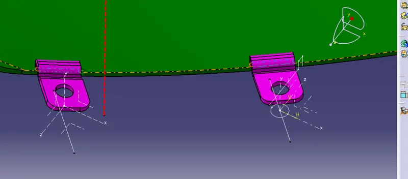
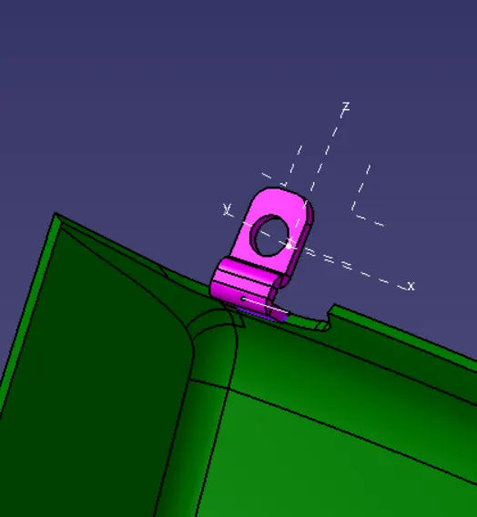
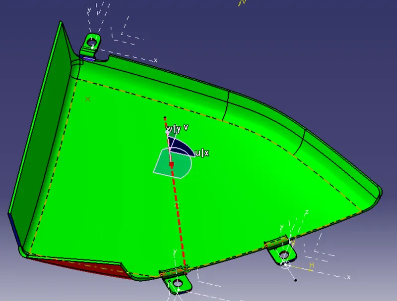
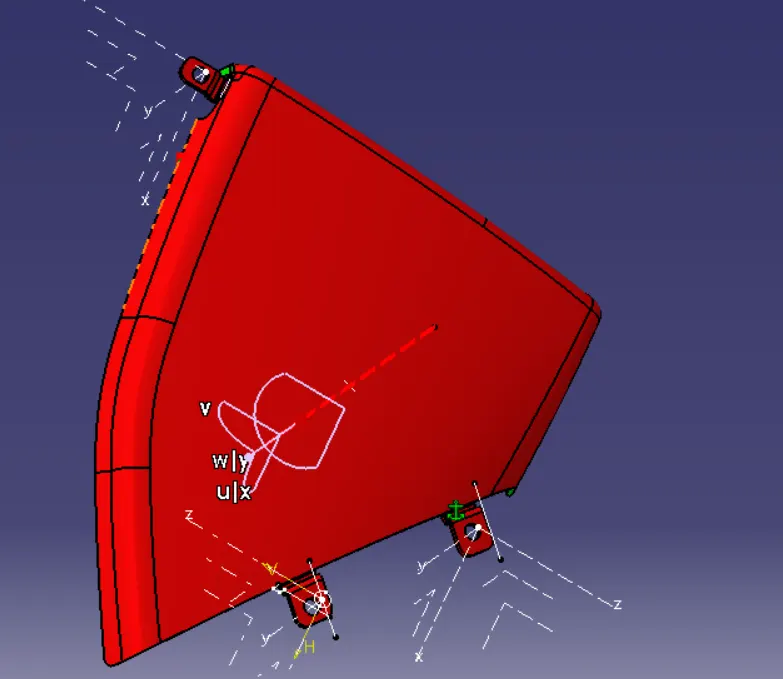
Flanges were created on the arm rest with the reference dimensions from the master sketch provided. The purpose of the flange was to provide slots for the heat stakes and locator which are required to assemble the two components together and constraint the motion between them.
BOTTLE HOLDER:
PRE-DESIGN CHECKS:
Before starting the creation of the class B surface we must ensure that the given class A surface is properly closed and the surface continuity is proper. This can be done either with the help of the join operation or by using the boundary feature.
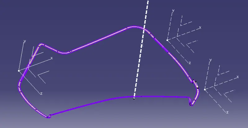
The surface received had a closed boundary but contained an extra surface extending as shown in the image which had to be trimmed in reference with the other parts.
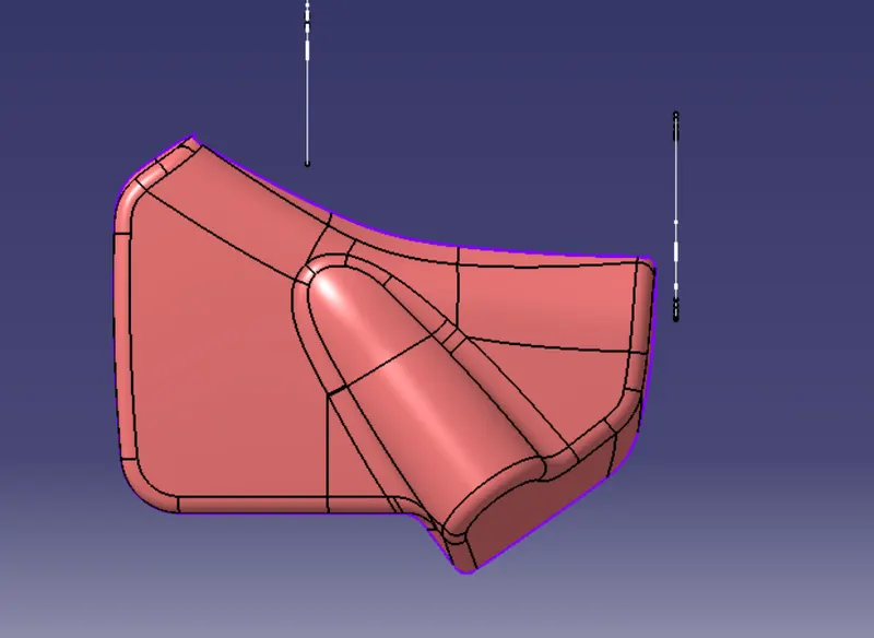
Fig: Class A of Bottle Holder
TOOLING AXIS:
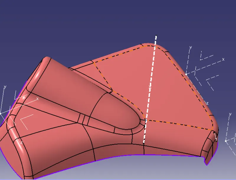
- The next step is to create the tooling axis for the part which will determine the direction in which the core and cavity of the mould will move.
- Designer must ensure that all holes and slots are covered in the main tooling and thus side core must be avoided whenever possible
- After analysing visually for the best possible tooling axis, an axis system is created on the centre of one of the surfaces of the lower substrate.
- First a dummy tooling axis is drawn along the Y direction with the axis system and the centre point as reference
- If the draft analysis is cleared with the dummy tooling axis then it is considered as our main tooling axis if not then the tooling axis is created with the help of bisecting method
DRAFT ANALYSIS:
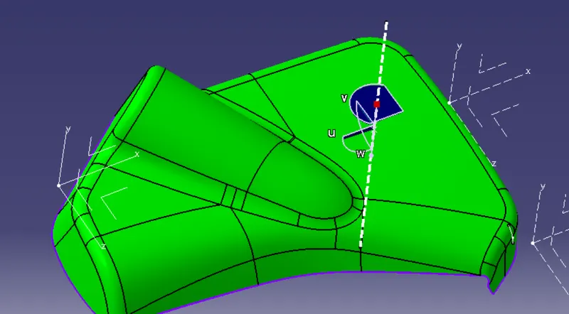
- Draft analysis is done on the class a surface after the tooling axis has been obtained
- The part must have a minimum draft angle of 3 degrees on all the tapered faces
- Using the feature draft analysis tool and the compass the part surface is validated for the minimum draft criteria
- It is very important to validate the tooling axis for the class A surface since it will be helpful in creating the class C surface
CLASS B SURFACE:
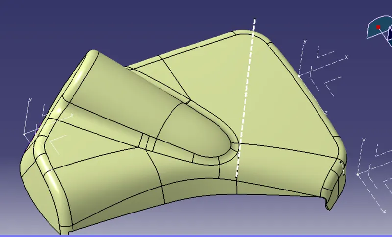
- After all the validation has been done, the class B surface is created by offsetting the class B surface to a distance of 2.5 mm
- After offsetting many openings in the surfaces are found which are closed with the help of multi sections-surface and sweep commands.
- The class B surface is then extrapolated in parts to trim it along with the class C surface
CLASS C SURFACE:
- The class C surface which connects the class A and class B surface is created by sweeping the boundary of the class A and using the class A as a reference.
- The sweep is divided into several parts in order to avoid complexity
- Surfaces which are parallel to the tooling direction are swept with the tooling axis as reference and with a draft angle of 3 degrees
PART:
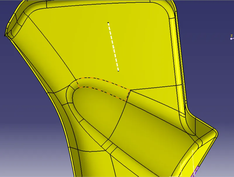
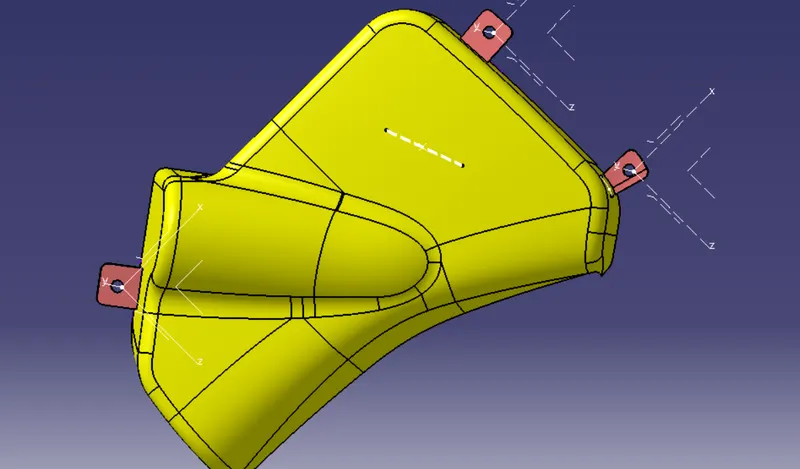
The final trim is created by joining the Class A and C surface and finally trimming it with the Class B surface. The combination of class A, B and C surface is then converted into a solid with the aid of fill command in the part workbench
FINAL ASSEMBLY:
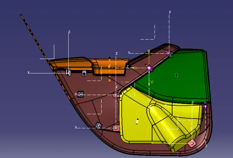
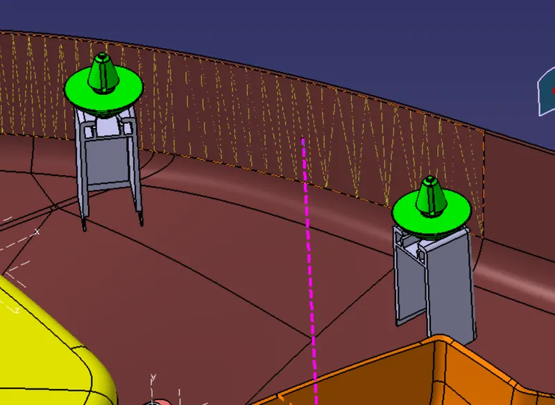
The final assembly of the door trim involved the insertion of the push clips into the respective dog house slots. Using the dog house central axis and the axis of the push pin coincident relation was given. After which, using contact constraint the push clips were made to sit in the dog house slot as required.
CONCLUSION:
- Tooling axis for each individual part was created an draft analysis was done
- Closed surface was created for all the parts
- Attachment strategy was decide and engineering features were created
- Push clips were assembled on to the dog house and the final assmebly was created