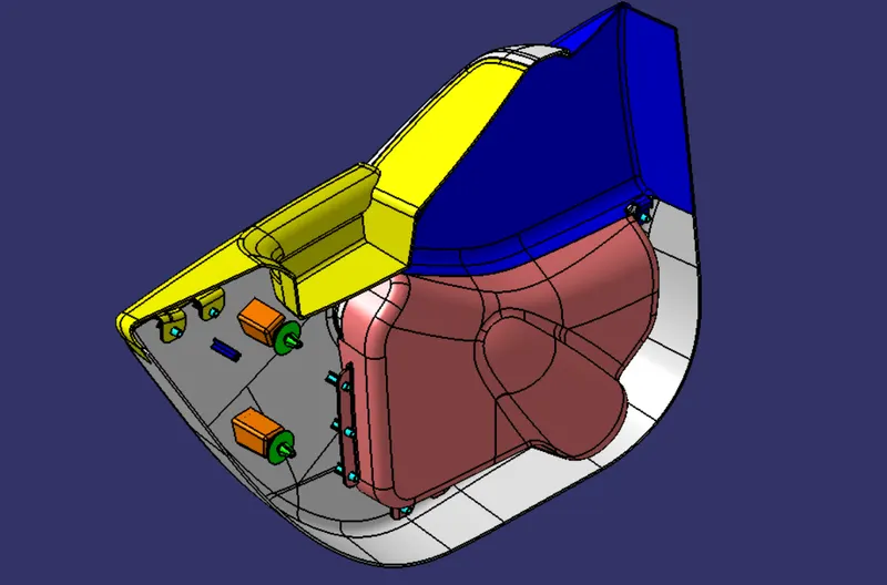
Week 11 - Final project
Week 11 - Final project:
Objectives:
- To create individual tooling axis for the parts and perform draft analysis on the class A surface
- To create the class B and class C surfaces from the given class A surface
- To form a solid geometry by combining all the surfaces
- To decide an attachment strategy for the part and create engineering features in reference from the master section provided
- To perform draft analysis on the solid part model with all engineering features
- To assemble all the components togehter to obtain the final trim
Input Surface:
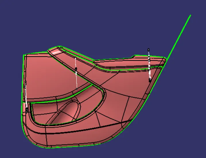
ArmRest:
Class A Surface:
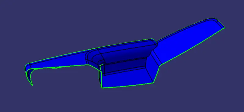
Class A surface with open Boundary
- After receiving the clasa A surface check the connectivity of the surface using join or by boundary.
- If it is not join together make it with a minimum tolerance of 0.001 to 0.003 and check for connectivity of the surface.
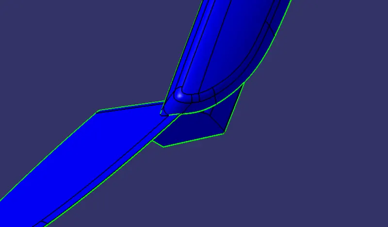
- In the given input surface there is a open boundary so using commands like extract, extrapolate, join and trim class A surface is created.
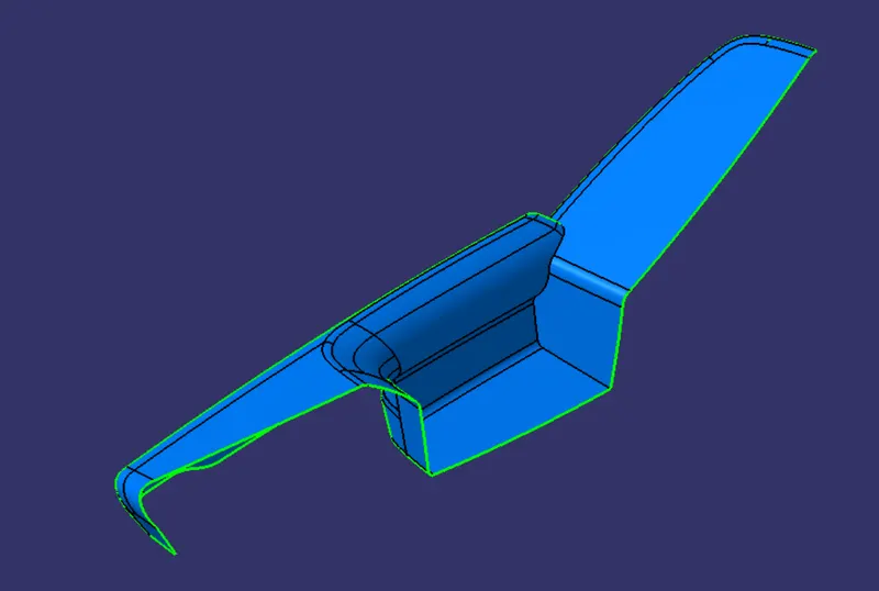
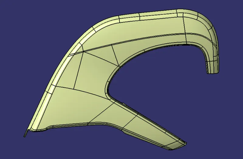
Class A Surface
ToolingAxis:
- The direction in which the mould open and closes is called the tooling axis direction.
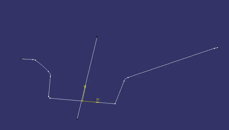
- Here, using project intersection along XZ and YZ plane is created and the two inclined lines were drawn inside the positioned sketch and Bisecting line is drawn from the inclined lines.
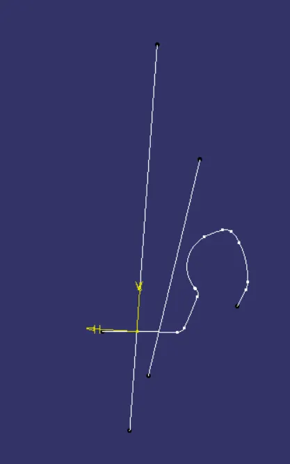
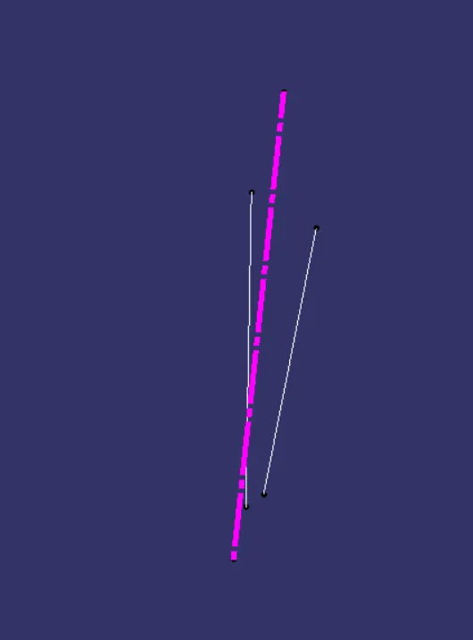
- Then Bisecting line is drawn from from the bisected lines of XZ and YZ planes respectively.
- Thus the Bisecting line is the Toolng Axis Line.
Draft Analysis on Class A Surface:
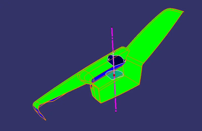
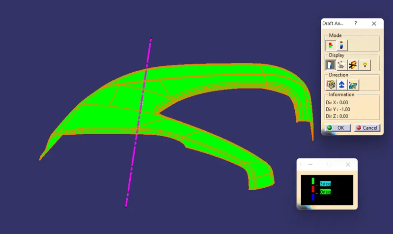
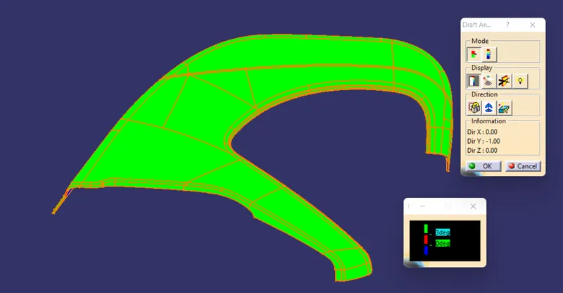
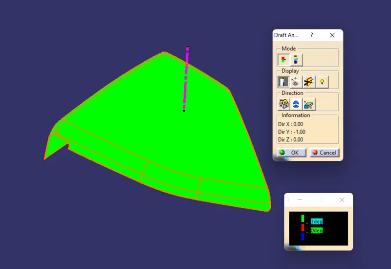
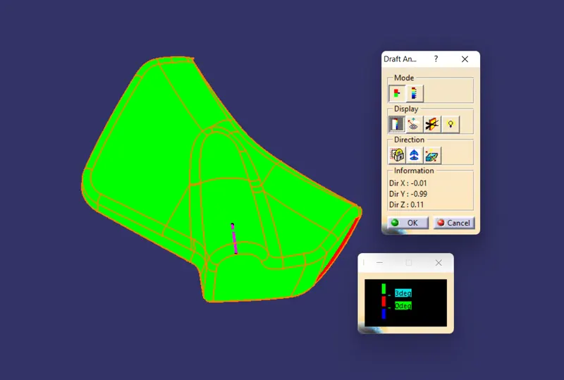
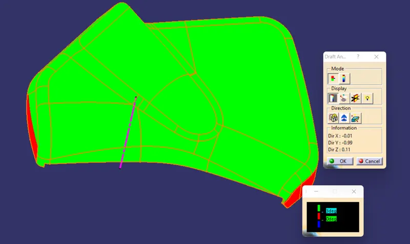
- The Draft Analysis command enables you to detect if the part you drafted will be easily removed. This type of analysis is performed based on color ranges identifying zones on the analyzed element where the deviation from the draft direction at any point, corresponds to specified values.
The colour scale on the bottom visualizes, whether the draft angle meets the requirements or not (3 deg) by indicating the colours Green, Blue and Red. We need to align and fix the compass to the tooling axis then the draft angle analysis will be checked out.
Class B Surface:
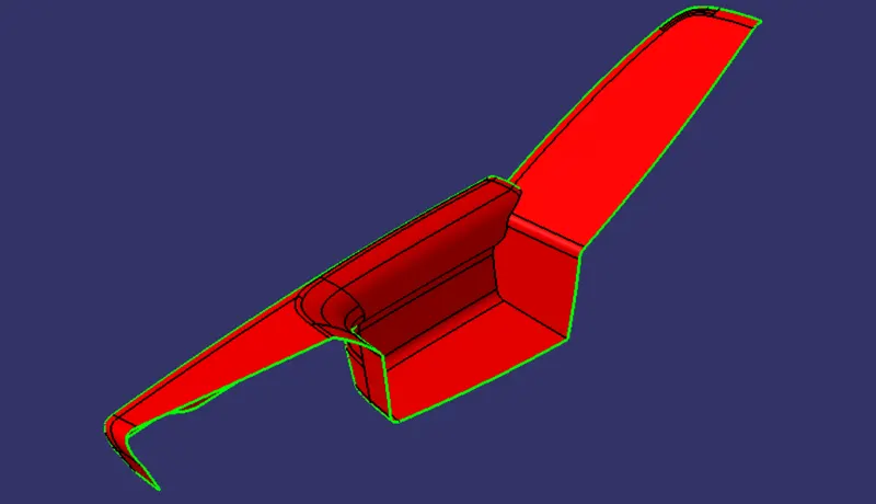
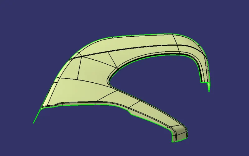
- Here Class B surface is created by offesting the Class A surface by 2.5mm(according to thickness).
- After offesting the surface some patches are found in the surface.
- By using commands like extract, Extrapolate and trim commands patches has been removed and a complete surface has been created.
Class C Surface:
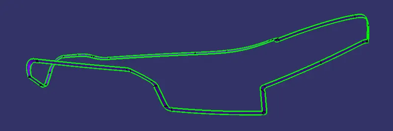
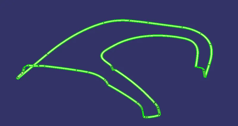
- By taking the boundary of the Class A surface and by using the sweep (reference by surface and with draft direction) method Class C Surface is created.
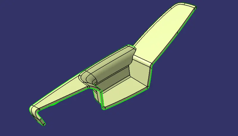
- By using Join command Class A surface and Class C are joined.
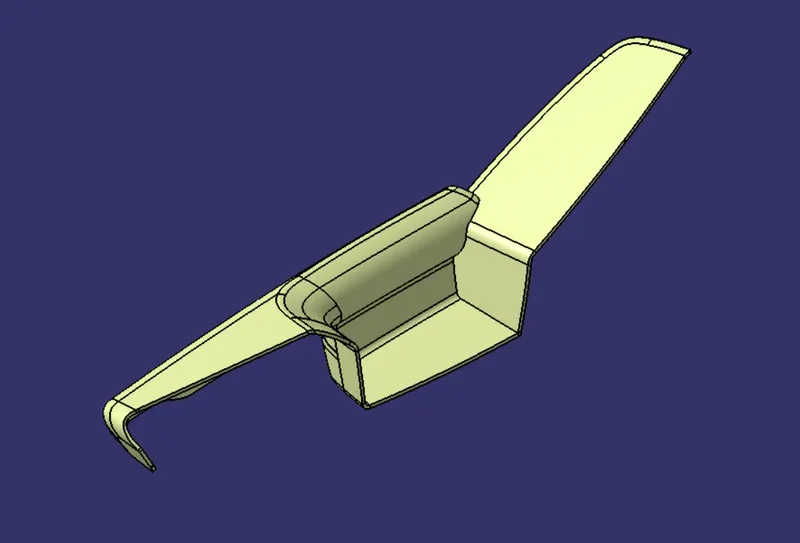
- By Trimming the Class AC surface with B surface the final surface has been created.
Draft Analysis on Final Surface Body:
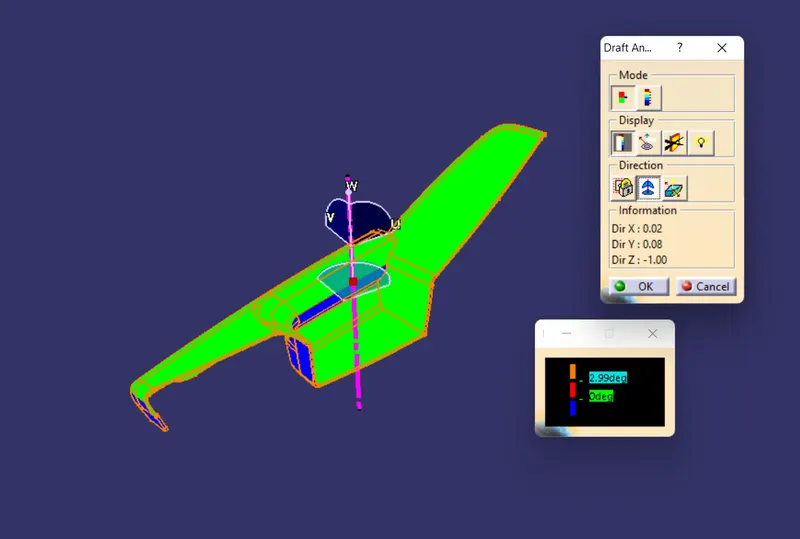
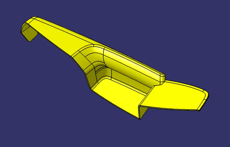
Final Closed Solid Body:
LowerSubstrate:
Class A Surface:
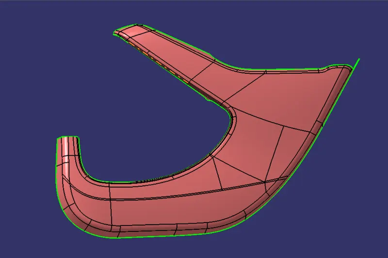
Tooling Axis:
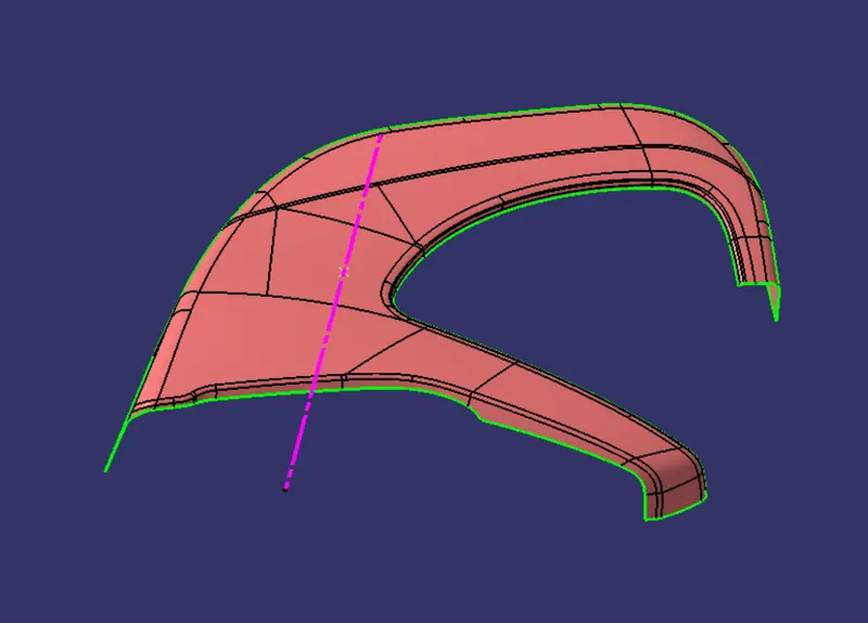
- Here Tooling Axis is created using point on direction method along Y-Axis.
Draft Analysis on Class A Surface:
Class B Surface:
Class C Surface:
Final Surface:
Draft Analysis on Final Closed Surface:
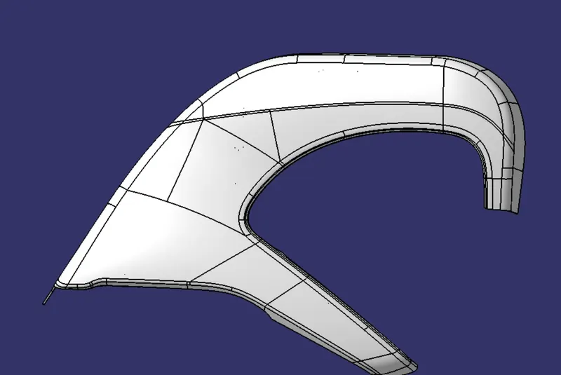
Final Solid Body:
MapPocket:
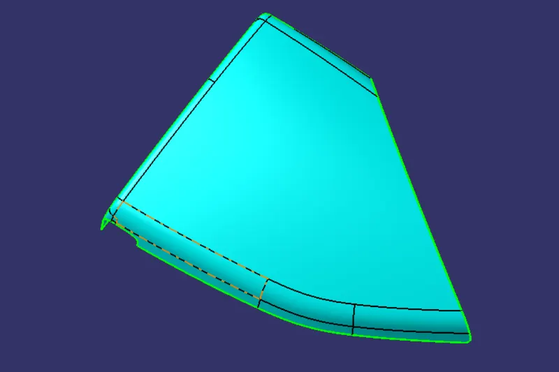
Class A Surface:
Tooling Axis:
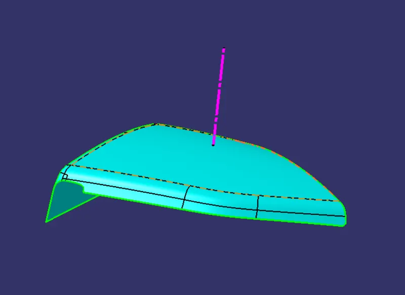
- Here Tooling Axis is created using point on direction method along Y-Axis.
Draft Analaysis on Class A Surface:
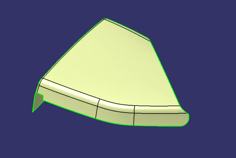
Class B Surface:
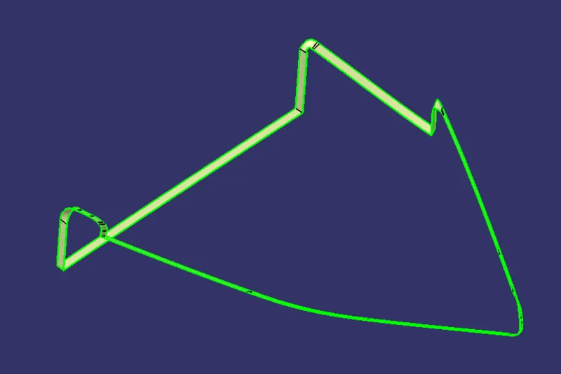
Class C Surface:
Final Closed Surface:
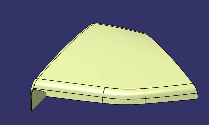
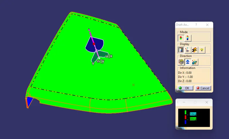
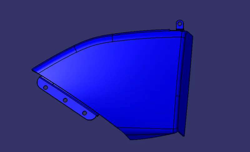
Final Solid Body:
BottleHolder:
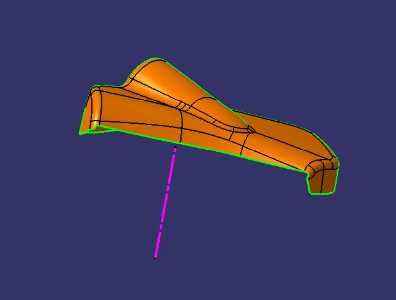
Class A Surface:
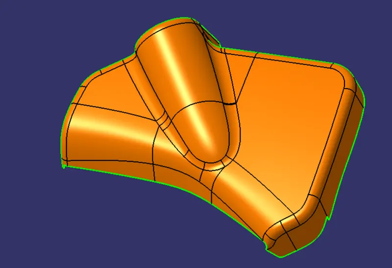
Tooling Axis:
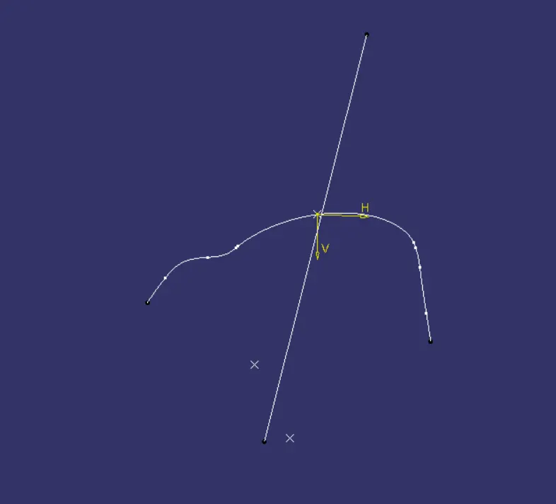
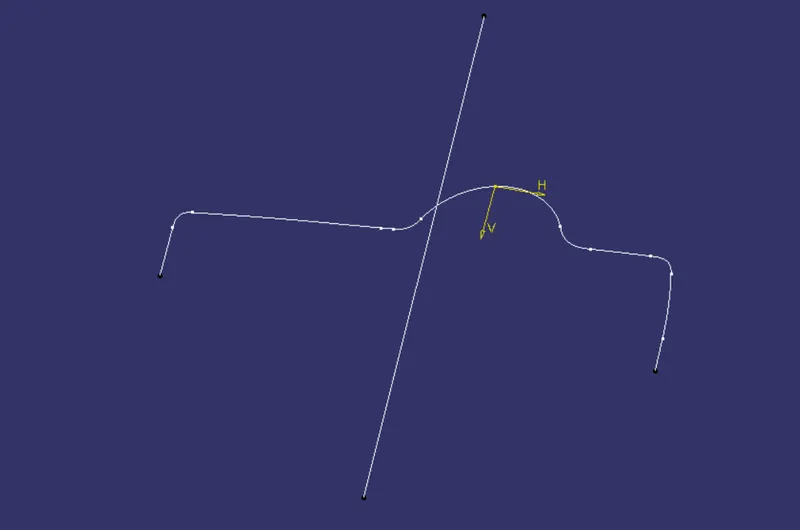
- Here Tooling Axis is created by using Bi-Secting Method
Draft Analysis on Class A Surface:
Class B Surface:
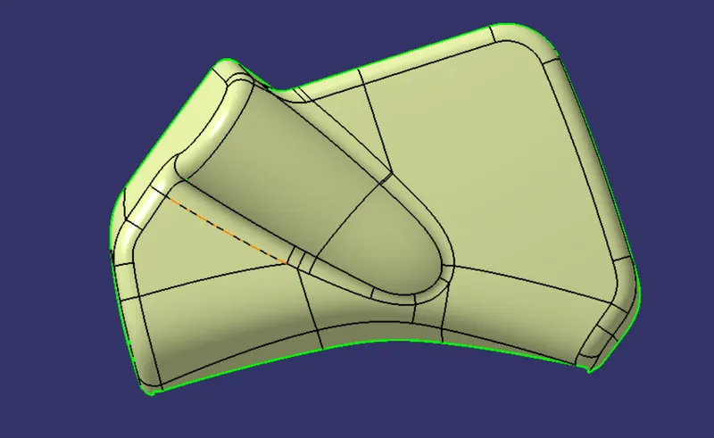
Class C Surface:
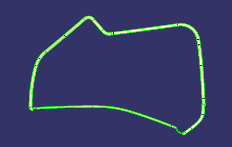
Final Closed Surface:
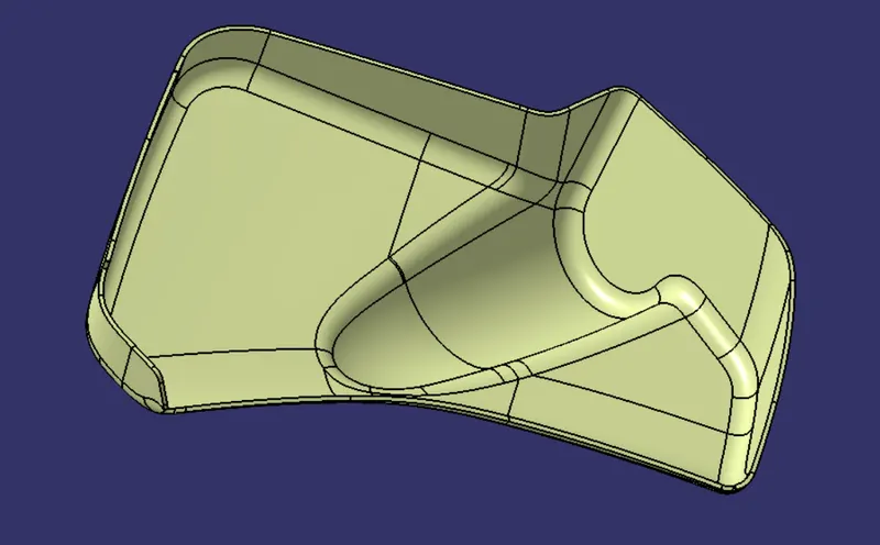
Draft Analysis on Final closed Surface:
Final Solid Body:
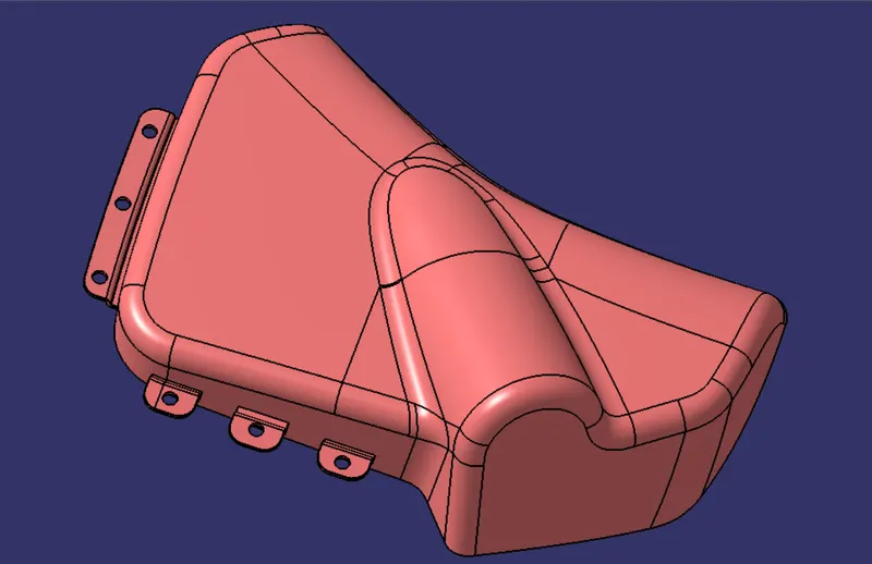
Enginerring Features / B side Features:
1.Flanges:
- All the flanges have been created by following the given master section. the thickness of the flanges is 2.5mm, the draft angle is 0.5 deg applied to all the flanges.
- slots for locators and heat stakes have been created onto all the flanges.
Arm Rest:
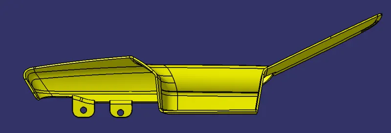
Map pocket:
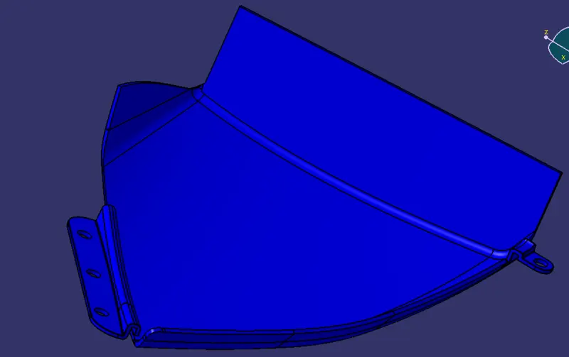
BottleHolder:
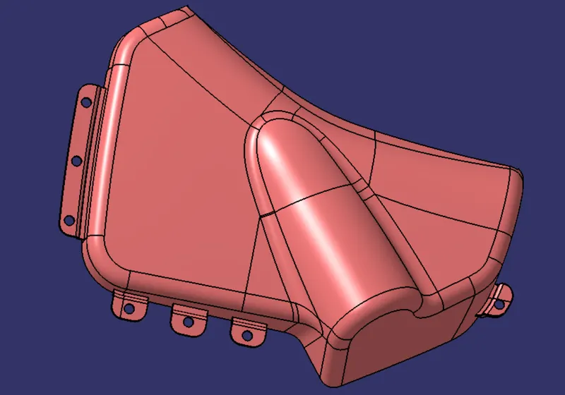
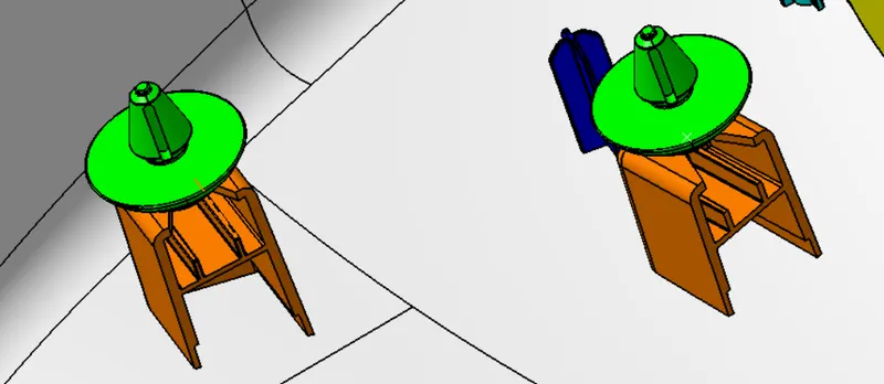
Heat Stakes:
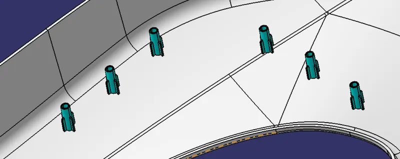
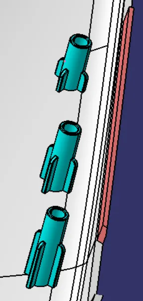
- The use of heat stakes is to attach two plastic components permanently.
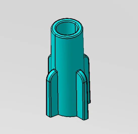
- Heat stakes are created in the Lower substrate according to the design rules and drafted for 0.5mm.
DogHouse:
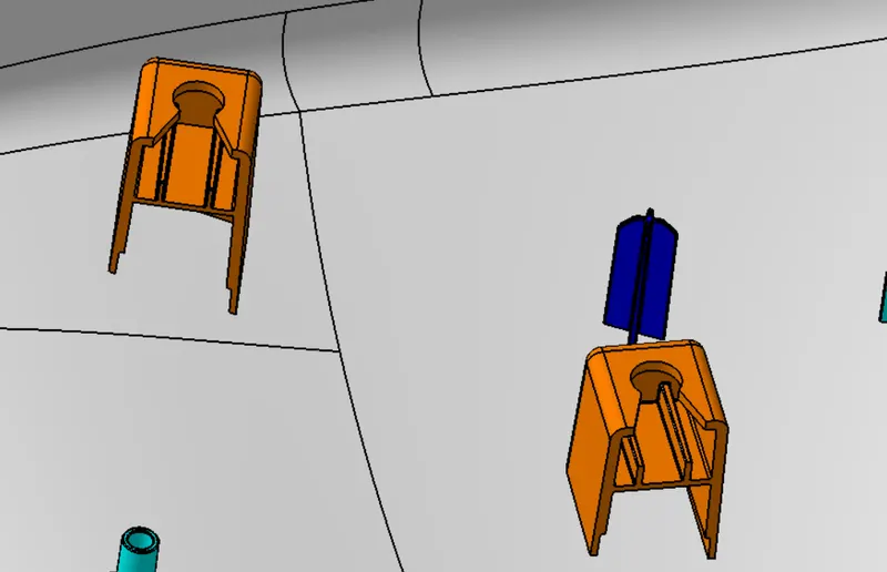
- The dog house is an engineering feature used in plastic design. Dog houses are used as supporting features sometime other engineering features like snaps, locators, etc are mounted on them to increase their strength. Dog houses are subjected to draft analysis to prevent breakage of the components during ejection from the mold cavity. dog house and other engineering components are built on the B surface.
Final Assembly in different orientation :
Front View:
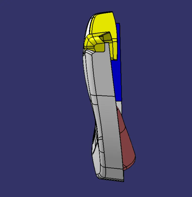
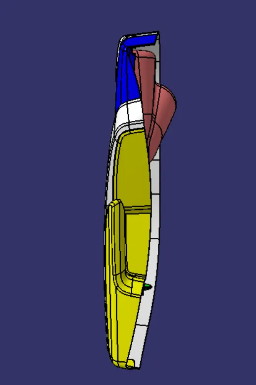
SideView:
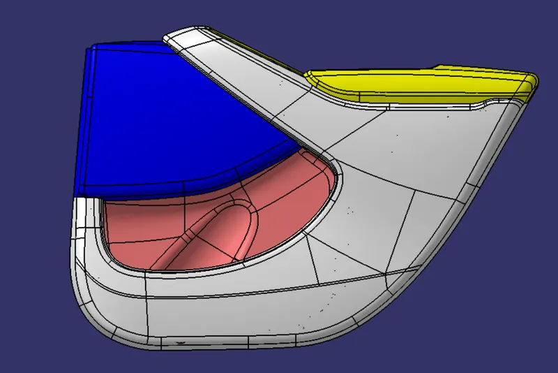
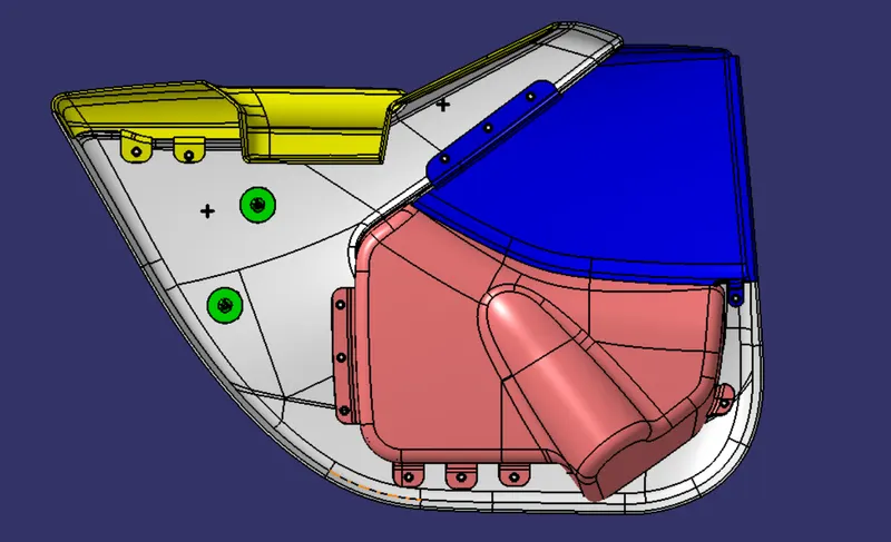
TopView:
Isometric View: