Week 11 - Final project
Aim :
In this project we are converting the given door trim surface to part body with B side features.
Tooling axis :
The direction in which the core and cavity of the mould moves is known as tooling axis. Tooling axis differes in every part based on its class A surface and also the master sections for class B surface.
Whenever the class A surface or master section is given first thing we have to detrmine or define is tooling axis. Based on the tooling axis core and cavtity for the part is developed.
Tooling axis design :
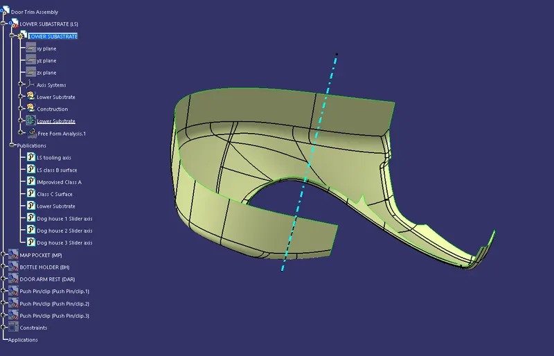
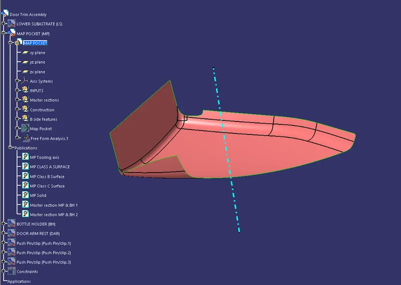
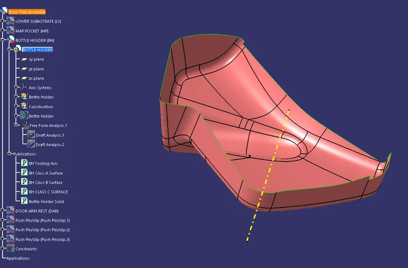
Create a poin on the surface >> then create a line normal to the surface or in the Y direction , in below case most of the tooling axis are created based on the direction normal to the surface.
Below images shows the tooling axis for all the given class A surfaces,
Local substrate tooling axis :
Map pocket tooling axis :
Bottle holder tooling axis :
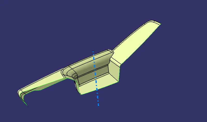
Door Arm Rest slider axis :
Slider Axis :
The direction in which the slider core for the part such as for dog house , holes , or any other projection . Slider axis is important as much as the tooling axis. It determines the movement of the slider core. Slider axis will be added if there is any projection ot any box shape in the part bady, apart from that some b side features like dog houses will have slider axis seperately.
Slider Axis creation :
Slider axis is created for the dog house or surface with any under cuts.
Below images shows the slider axis,
Door Arm Rest slider Axis :
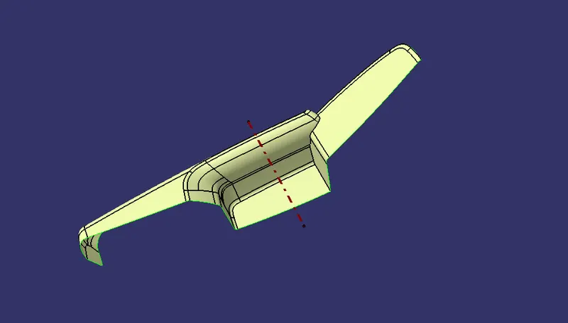
Dog house slider axis for lower substrate :
The three lines are the slider axis for the three different dog houses.
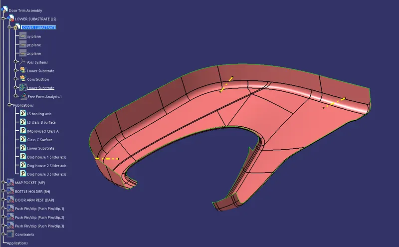
What is class A surface :
class A surface are those surfaces which are curvature continuous while providing the simplest mathematical representation needed for the desired shape/form and does not have any undesirable waviness. Curvature continuity: It is the continuity between the surfaces sharing the same boundary.
Class A surface is a imaginary design surface based in which the part body is designed. class A surfaces are either extracted from the previous part or in case of development a new clas A surface is developed by the class A surface designers.
Below images shows all the given class A surfaces,
1) Lower substrate class A surface :
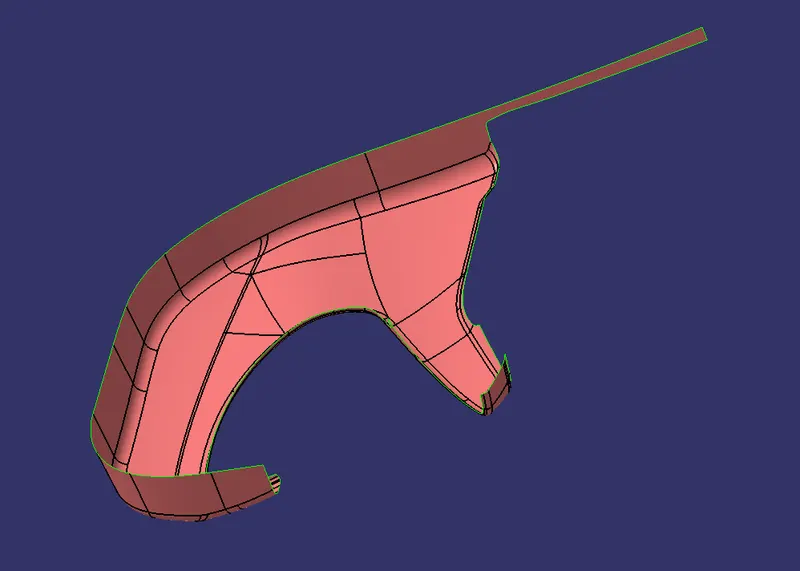
2) Map pocket class A surface :
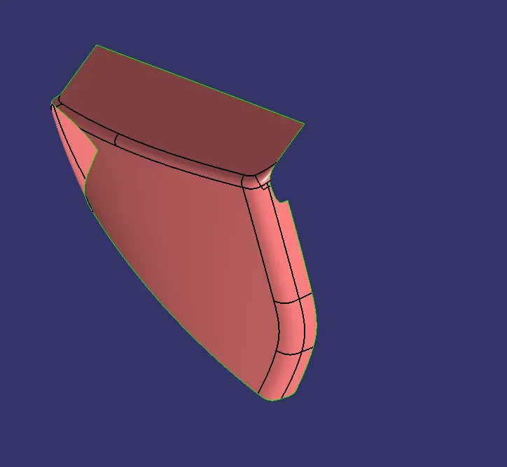
3) Bottle holder class A surface :
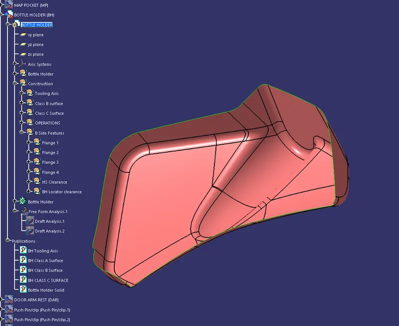
4) Door Arm Rest class A surface :
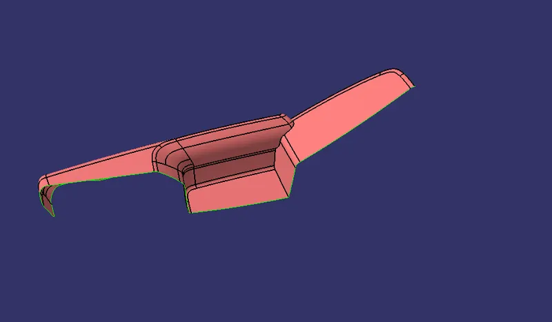
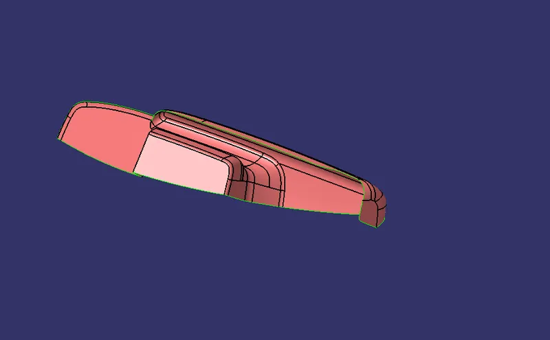
Improvised class A surface :
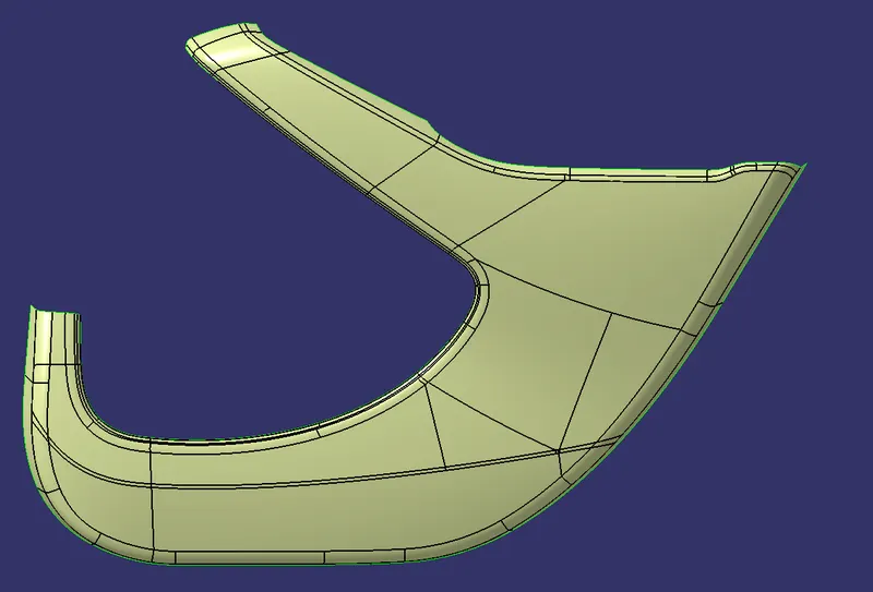
In several cases the given class A surface can not be completely converted into part body, there we need to give some modifications to the given class a surface . Such surfaces are named as improvised class A surfaces.
Improvised class A surface of local substrate :
What is class B surface :
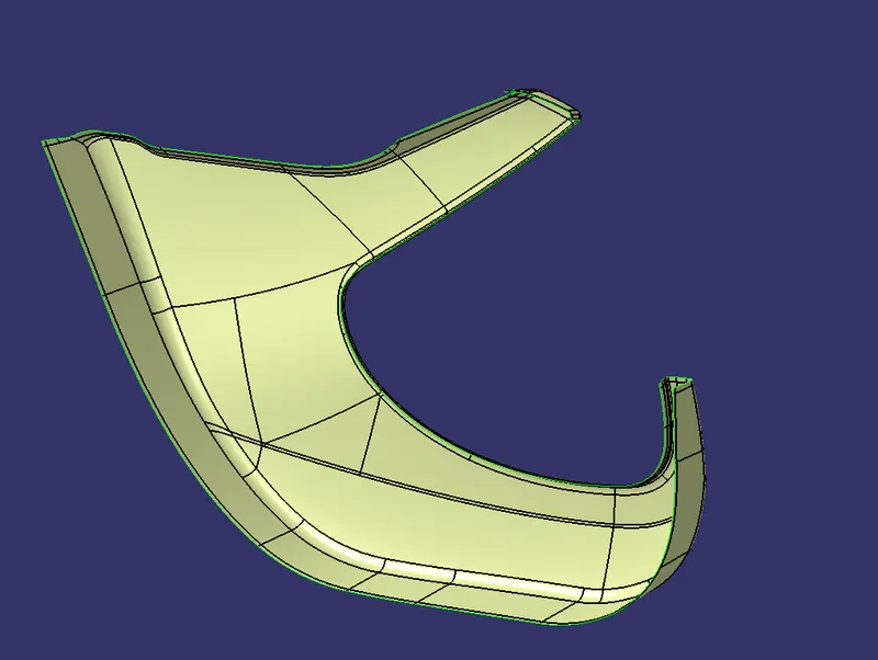
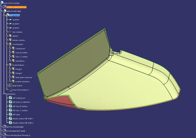
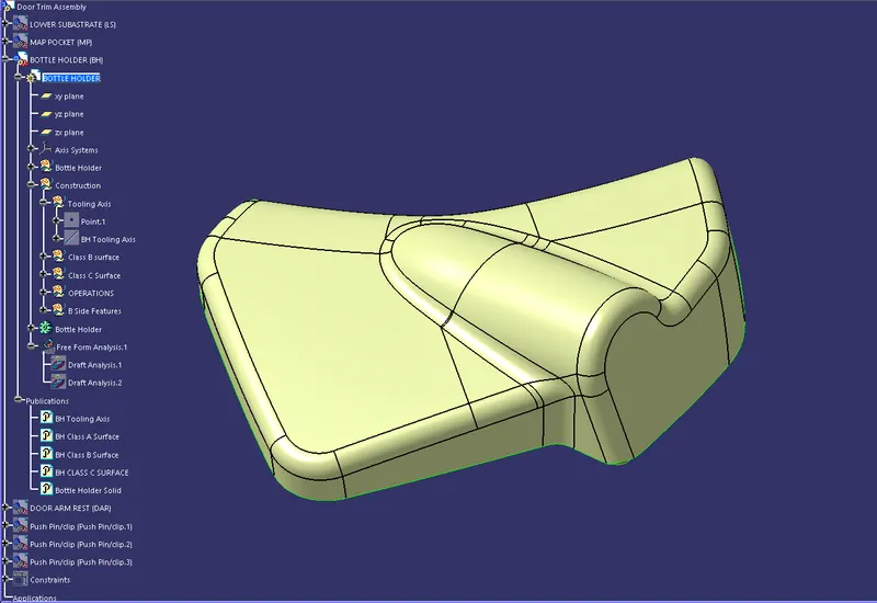
Class B surface is the secondary surface created based on the thickness of the part body. Class B surfaces are basically offset surfaces of class A Surface. in some cases class B surfaces are created by extracting the surfaces from class A and working with it.
Class B surfaces are the secondary surfaces that you can see sometimes, but are less important, such as the inside of your glovebox, ash tray, etc.. These must be smooth and "error-free" as well, but are not held to the standards that class A surfaces are.
Class B Surface images :
1) Local substrate :
2) Map pocket :
3) Bottle holder :
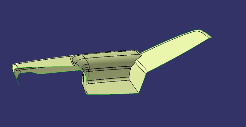
Difference betweeen Class A and Classs B surfaces :
| Class A surface | Class B Surface |
| Class A surfaces are visible surfaces, that when a class A surface is converted into part body the A surface side of the part body will be visible. | Class B Surfaces are secondary surfaces that will not be visible when attached with the other parts. They are generally the offset of the visible surface. |
| Class A surface will not have any attachment features it will be smooth and also have the designs that will add value to the part. | Class B surfaces will have attachment features like heat stakes, locators, doug houses, push pins , snap fits etc |
Class C Surface :
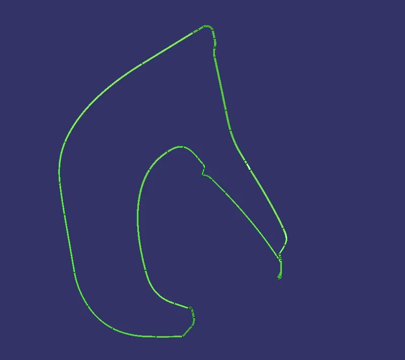
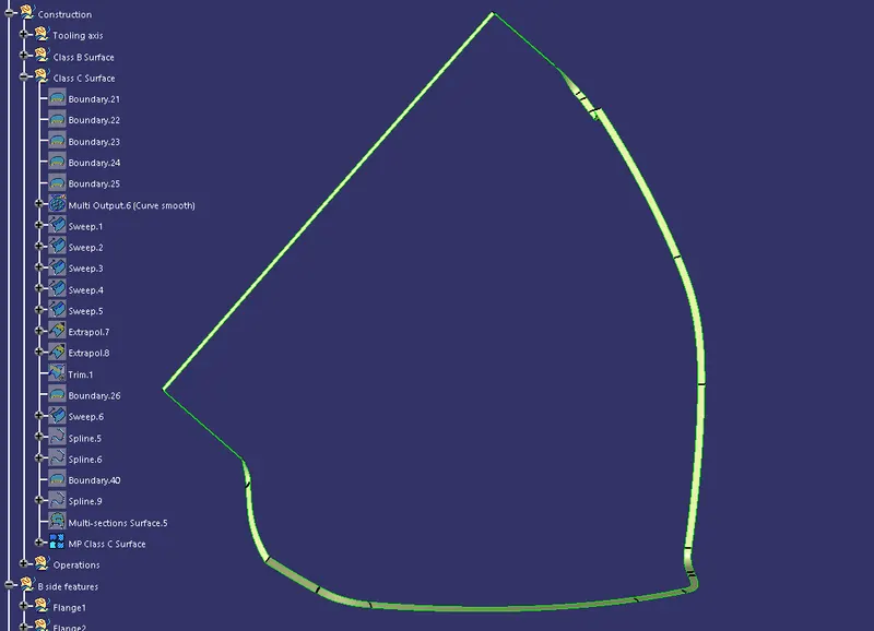
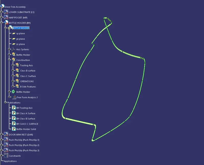
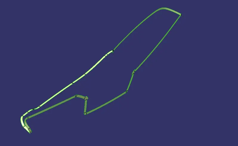
Class C surfaces are the backside surfaces that can have tool marks, flash and other imperfections without hurting appearance, function, etc.. Class C surfaces are developed by extracting the boundaries from the given class A surface and are swept along with the surface or with the tooling axis as guide curve in some parts. Mostly complex class C surfaces are swept with the help of surface only.
Lower substrate class C surface :
Map pocket class C surface :
Bottle holder class C surface :
Door arm rest class C surface :
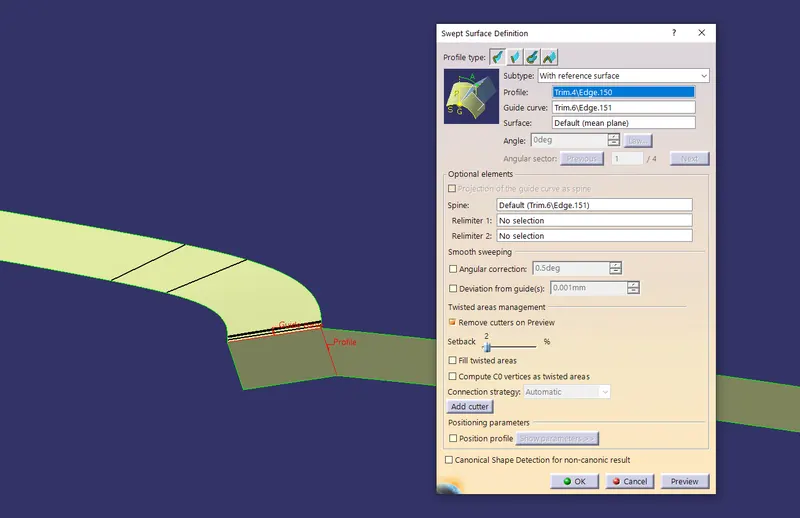
Final Part :
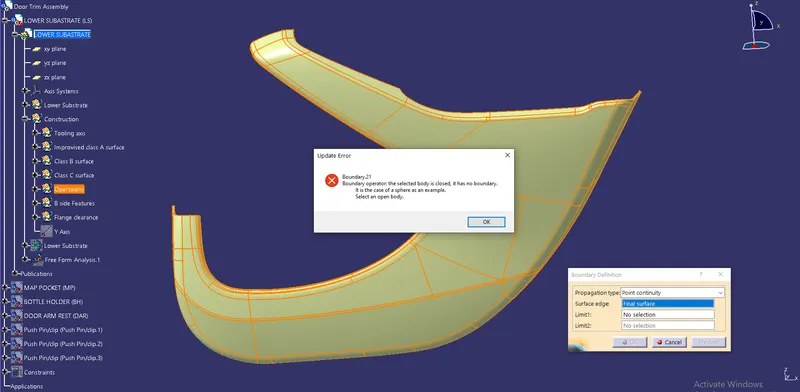
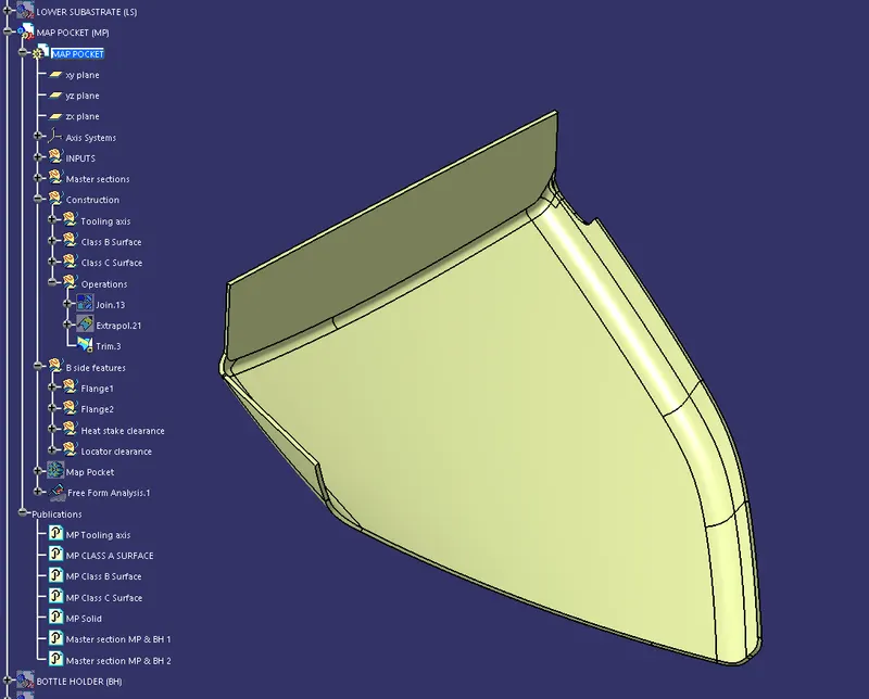
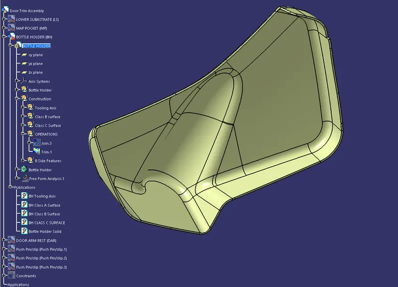
Final part is created by trimming the joined A and C surfaces with the class B surface created. After triming we can check the parts are fully joined are not by creating the boundary for the final part. If errroe message is showed during the boundary creation the final part is complete and can be converted into part body.
1) Lower subsatrate :
2) Map pocket :
3) Bottle holder :
4) Door arm rest :
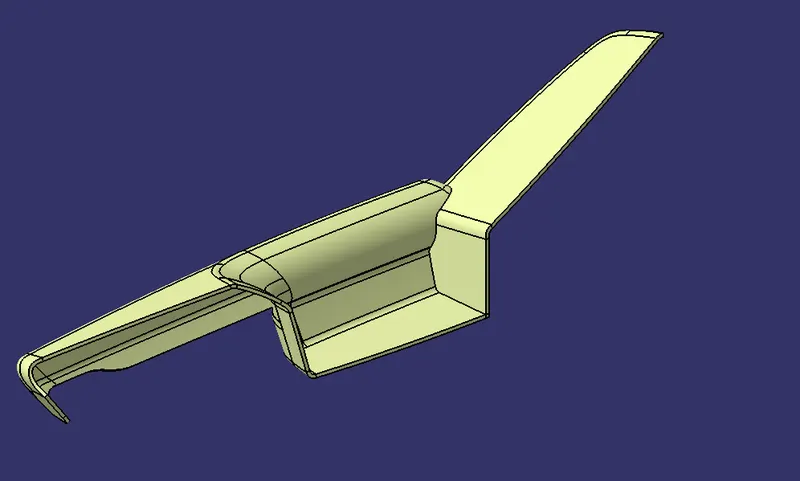
Solid Body :
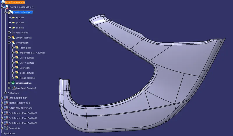
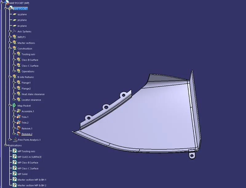
The final part is converted to solid body using the clossed surface tool in the part body work bench. All the class A , B & C surfaces are created in surface design work bench.
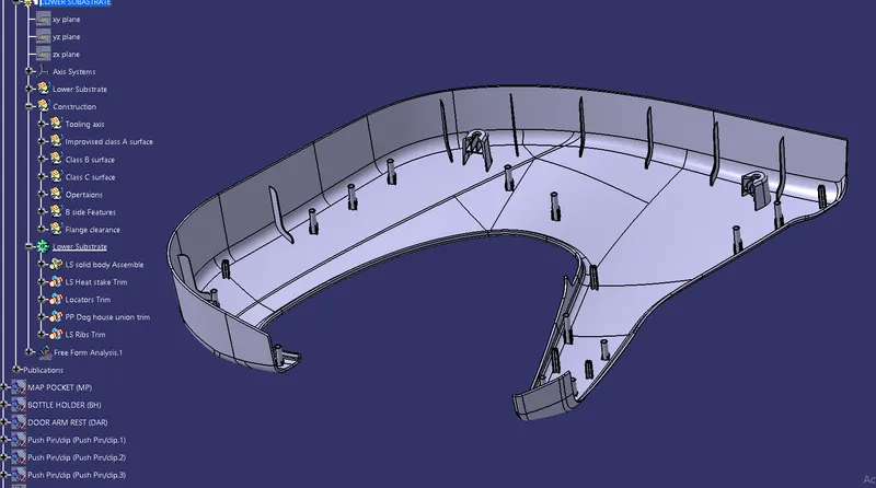
1) Lower substrate part body :
2) Map pocket part body :
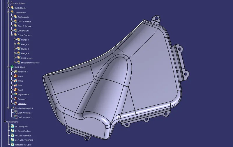
3) Bottle holder part body :
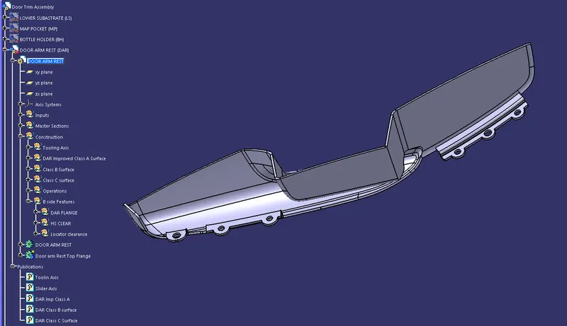
4) Door arm rest part body :
B-side Features :
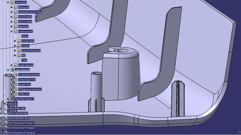
The B-side of the mold will often have more complicated and protruding features. These features allow the plastic to cool onto that side and away from the A-side. At the same time, allowing the plastic to stick and shrink too hard will make the part eject forcefully or get stuck in the mold.
The below image shows the multiple B side features like Dog house , Ribs , Four way locator , Heat stakes with stiffner.
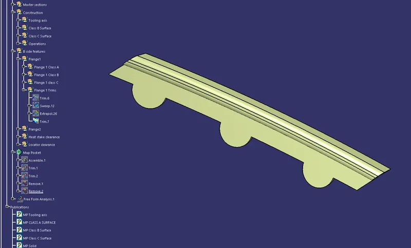
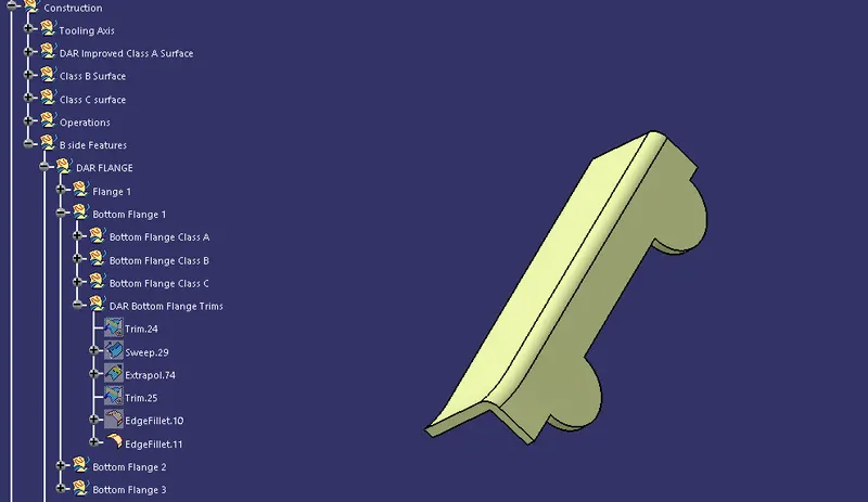
The below image shows the closed surface of the flange created for the door arm rest.
Draft Analysis :
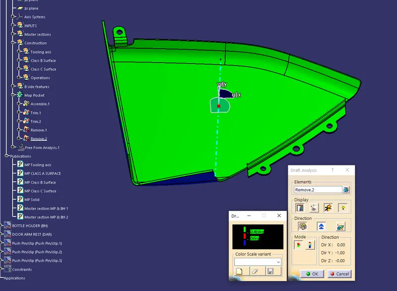
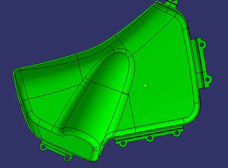
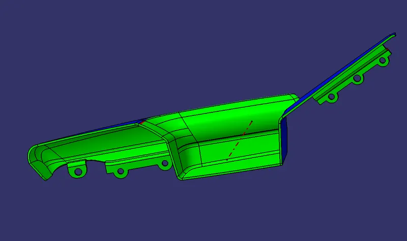
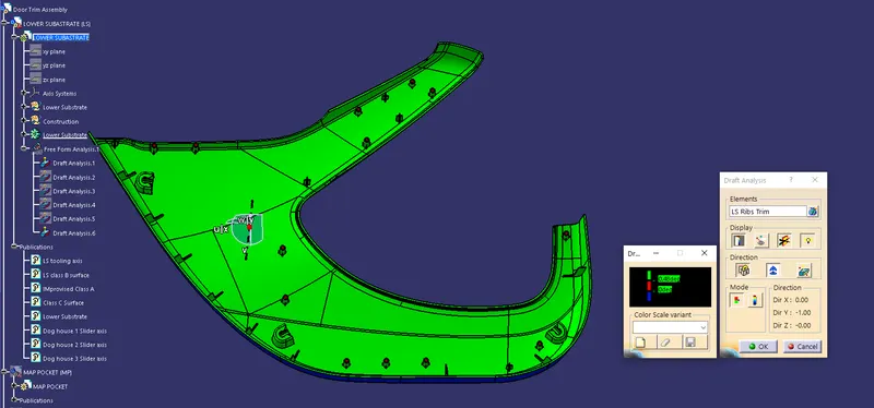
Draft analysis is done to verify the part creation will come under the design criteia with a draft angle of minimum 0.5mm. Draft analysis is done for all the part bodies with respect to their respective tooling axis.
Draft analysis for map pocket :
Draft analysis for bottle holder :
Draft analysis for Door arm rest :
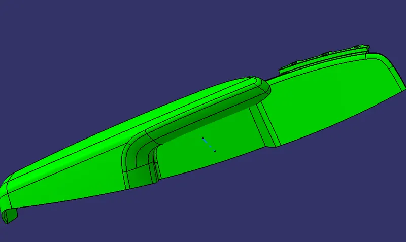
Draft analysis for Lower substrate :
Assembly :
Change the work bench to assembly then open multiple parts using insert part tool in the assembly work bench.
Here