Week 11 - Final project
Development of a door trim panel
inputs provided-
1. class A surface
2. Master section including attachment features
The door trim panel input consists of four components-
1.Lower substrate
2.Arm Rest
3.Map pocket
4.Bottle holder
Steps involved in the creation of door trim panel
1.Draft feature analysis of the Class A surface
2.Tooling axis creation
3.Creation of class B surface
4.Creation of class C surface
5.Final trim the surfaces to form the close surface and creation of part body.
6.draft feature analysis of the part body.
7.Creation of B side features like heat stakes,Dog House, flanges and locators from the master section provided.
8.The above steps are followed in every component and assembled to form door trim panel.
Lower Substrate
Draft feature analysis of the Class A surface
The given class A surface is created in a different styling software and is provided as an input to the CAD software for surface work.
The class A surface is generally visualised for draft feature analysis along axis system and studied for the direction of tooling axis
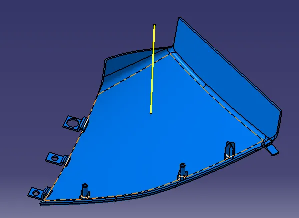
Tooling axis creation
what is tooling axis?
The direction in which the core and the cavity blocks move is the tolling axis direction.
The tooling axis creation is done by the bisecting method where lines are drawn on the walls coinciding which are parallel to the required tooling direction and their bisection is taken as the tooling axis.
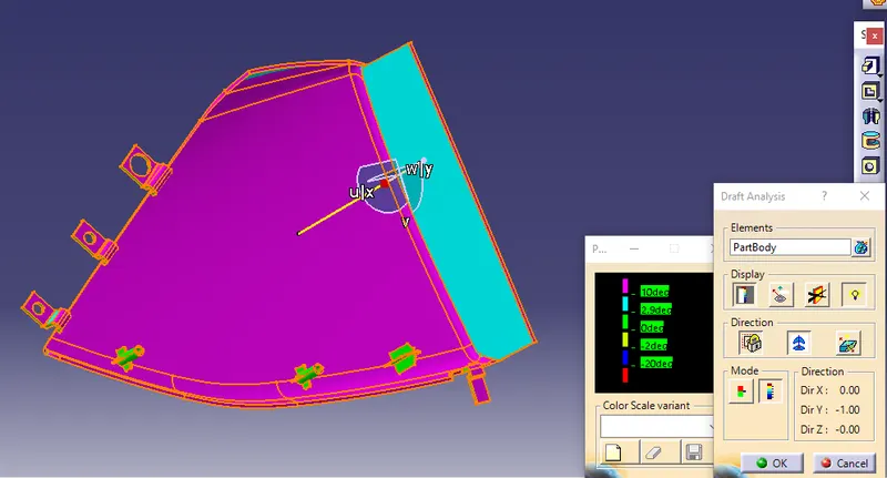
Draft feature analysis
Draft is provided to a component because of the smooth retraction of the core and cavity blocks with respect to the plastic component.
If draft is not provided,the core and cavity blocks walls get rubbed to the solidified plastic component created and would damage it.
hence in the automotive industry all the plastic components will be provided with a minimum draft of 3° with respect to tooling axis
Steps involved in creation of draft feature analysis
1. going to the insert, draft feature analysis
2. going to view mode customisation, selecting the material mode.
3. Class A surface is selected, the compass is placed on the tooling axis and locked.
4. different colour variations are provided for different angles
0°-2.9° green colour is given
2.9°-10° blue colour is given
> 10° pink colour is given
from the draft feature Analysis,the direction of the tooling axis is confirmed.
Creation of class B, class C and trim with class A surfaces
Class B surface is offset from the Class A surface at a distance of 2.5 mm.
Class C surface is swept on the boundary of the Class A surface perpendicular to the surface.
class A surface and class C surface are joined together and trimmed with class B surface to get final closed surface.
Using close surface command the part body is obtained.
draft analysis is performed on the part body also.
Creation of B-side features
Creation of heat stake
heat stacking is the process of joining to be similar materials using heat gun.The created heat stake is melted upon joining.
The main advantage of heat staking is that the fastening process is done in a very short cycle time at once when compared to other fasteners.
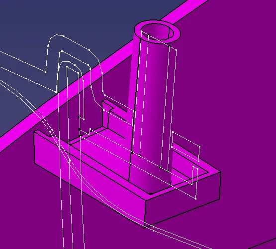
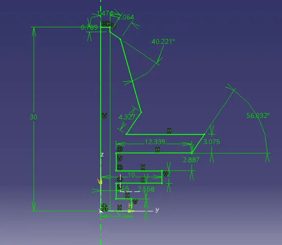
The position of the heat stake is obtained from the given master section as shown in the figure below.
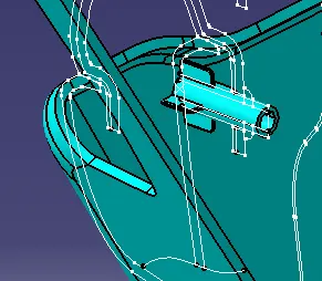
The required sketch for the heat stake is drawn on the plane by taking reference from the master section.
from the master section the dimensions of the heats stakes are-7.5 mm Outer diameter, 4.5 mm inner diameter and a height of 25mm.
The heat stake is given a draft of .5° with respect to the tooling axis on both the outer and inner surface.
ribs for the support of heat stake is also provided with all the design guidelines as shown in the figure below.
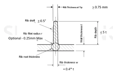
Taking the rib thickness as 1mm up to a height of 10 mm and providing draft of .5° with respect to the tooling axis.
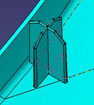
Creation of 2-way and 4-way locators
Locators are used to fix the position of the components to each other in the process of attachment.
any component will have 12 degrees of freedom for movement. The locators will arrest the degrees of freedom.
A 2-way locator will arrest one translational motion and two rotational motions.
A 4-way locator will arrest two translational motion and all three rotational motions.
design guidelines for creation of locators is same as the ribs and the height should be greater than the heat stakes.
Creation of Dog house
Doghouse is a component used as a supporting feature to the surface for fastening processes and fixing heat sticks, screw boss etc
in this project the dog house is supporting the pushpin.
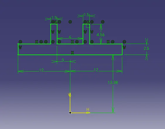
coring is done at the bottom of the doghouse with thickness to be 0.4 Times thickness of the Lower substrate which is 1mm and height 3-6mm.
A draft is created for the support of the pushpin.
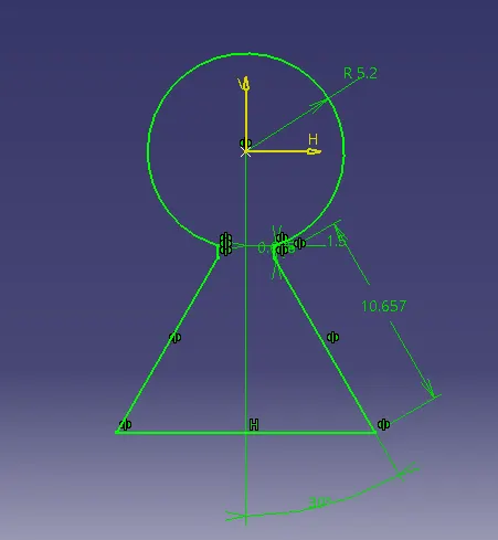
The dimensions for the sketches shown below are taken from the measurements of the pushpin provided as the input.
doghouse tooling axis is created at the opening side and a draft of .5° is provided to all the walls parallel to the tooling axis of the doghouse and also to the tooling axis of the lower substrate.
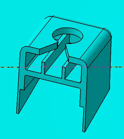
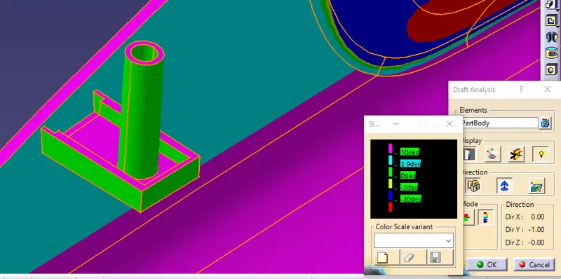
Draft analysis of the doghouse from the Main tooling axis
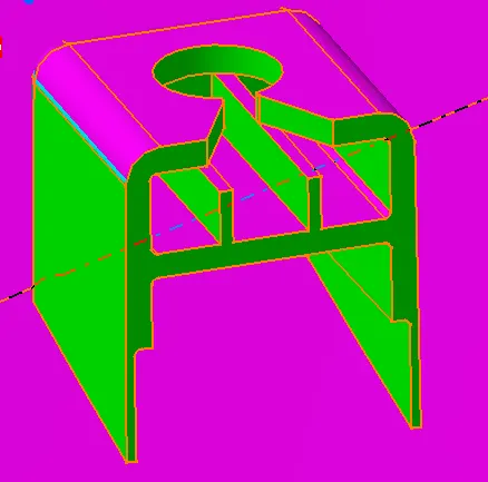
Draft analysis of the dog house from dog house tooling axis
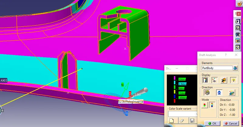
Draft analysis of lower substrate
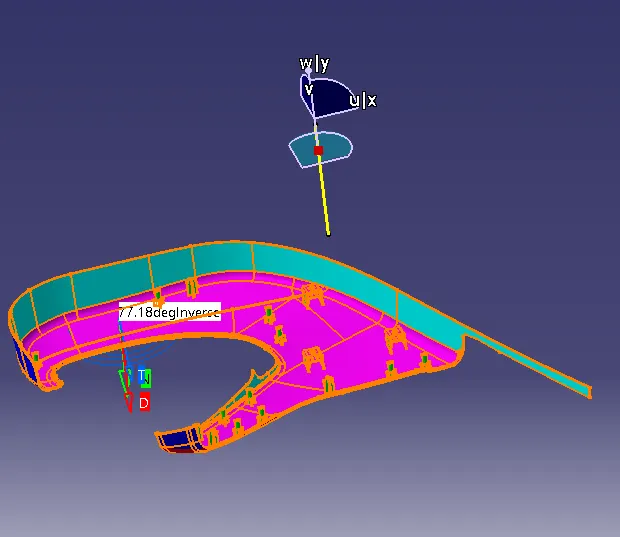
All the above procedures as explained in the lower substrate component is performed on the other three parts.
ARM REST
The input class C surface is as shown below,from the visual inspection it is found that the component should also have a side tooling axis, hence draft analysis is done on both the tooling axis.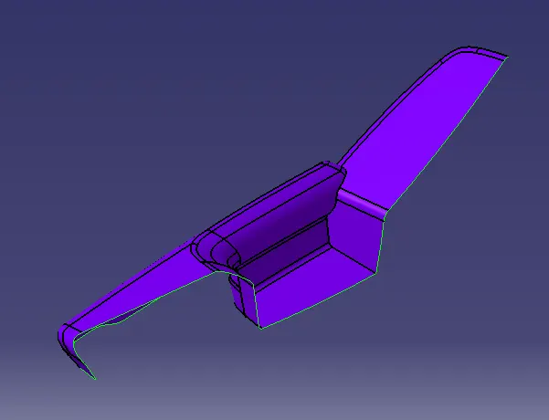
Draft analysis of the arm rest from Main tooling axis is shown below
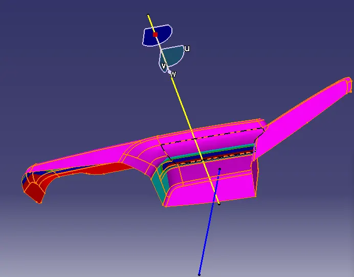
draft analysis of the armrest from side tooling axis
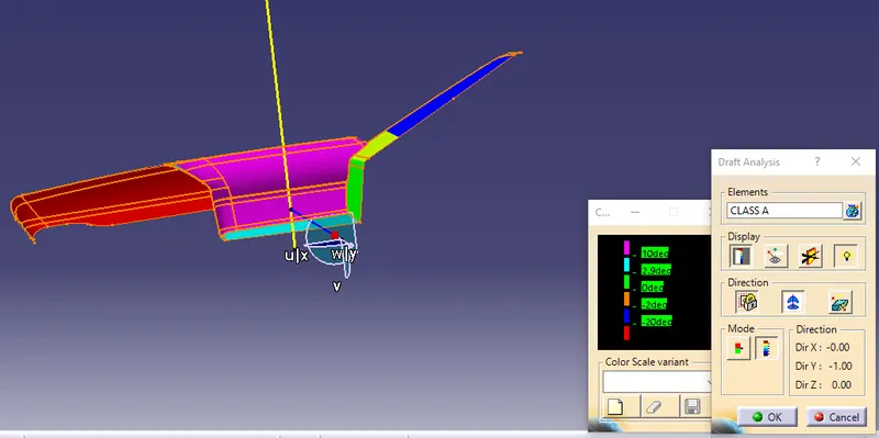
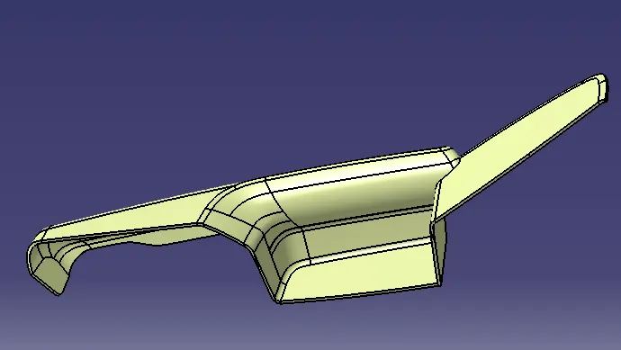
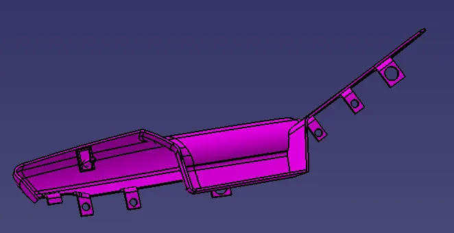
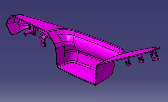
Final part body from the close surface
B-side features
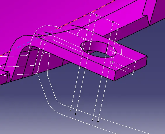
CREATION OF FLANGE
Draft analysis of the heat stake with the doghouse from main tooling axis
Draft analysis of the flange from side tooling axis
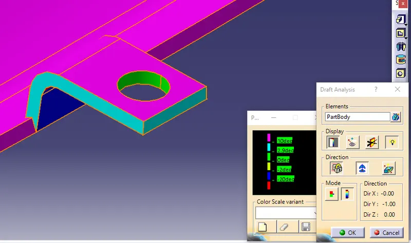
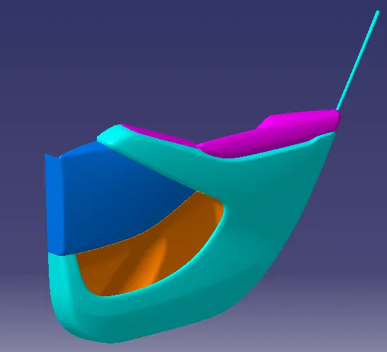
Final image of Arm rest
BOTTLE HOLDER
Class C surface as an input
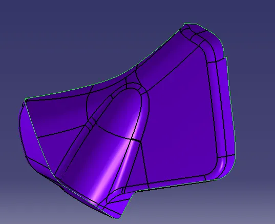
Draft analysis of the class C surface

Draft analysis of the complete bottle holder
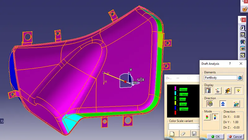
Final image of the bottle holder
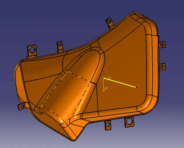
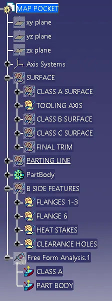
MAP POCKET
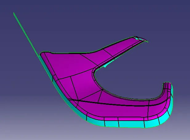
Class C surface of the map pocket
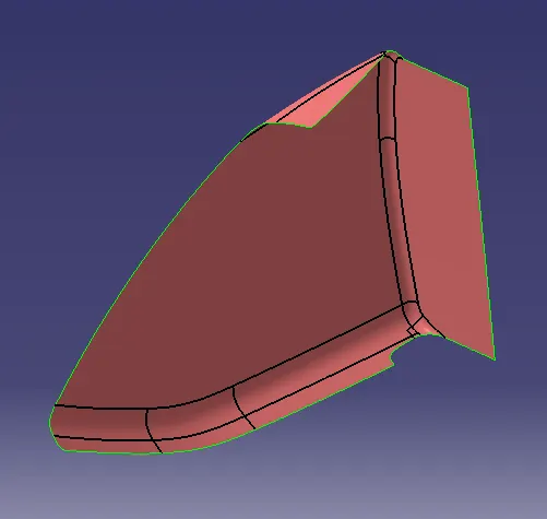
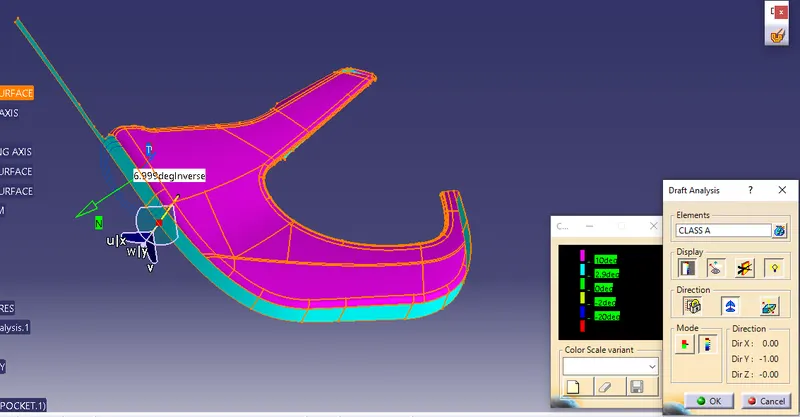
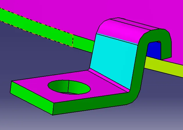
Draft analysis of the map pocket
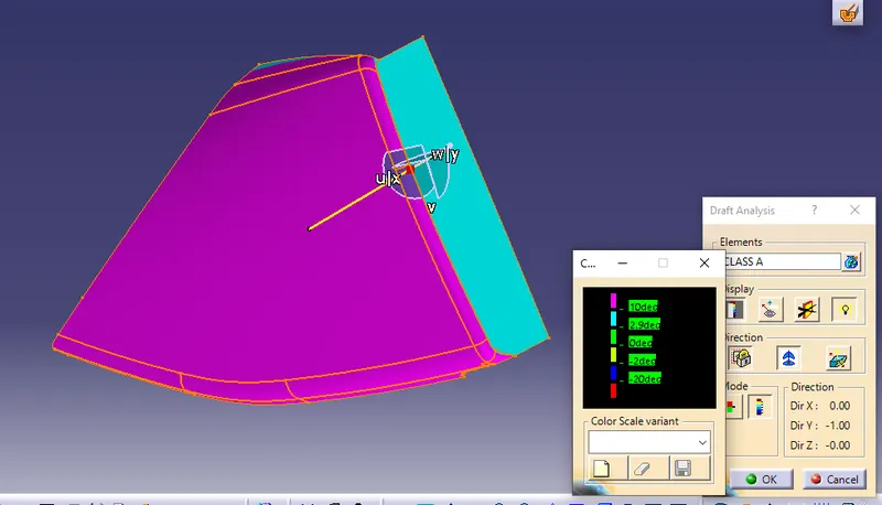
Draft analysis of the complete map pocket with B-side features
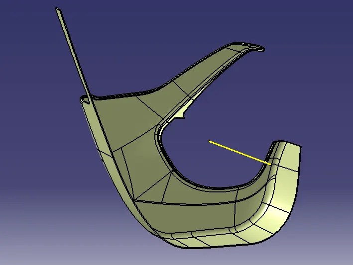
Final image of the map pocket
PUSH PIN
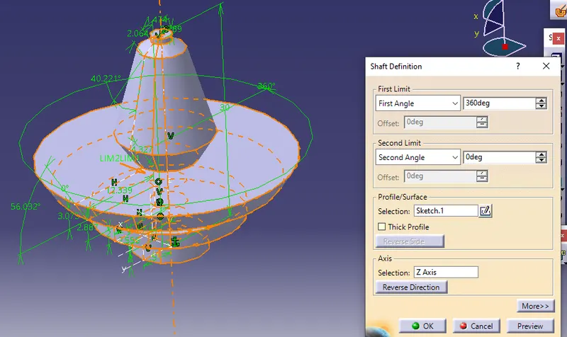
ASSEMBLY
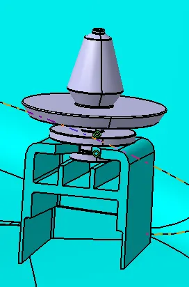
Fix constraint is given to all the four components of Door trim panel.
Push pin is assembled to the Dog House on the top surface of it by
1.coinciding the axis of push pin and hole axis of Dog House.
2.coinciding the contacting supports of the two components.
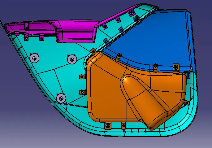
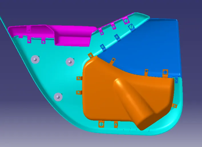
FINAL IMAGES OF THE DOOR TRIM PANEL
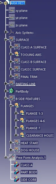
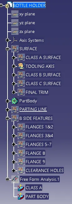
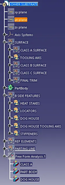
TREE STRUCTURE OF THE COMPONENTS
ARM REST
BOTTLE HOLDER
LOWER SUBSTRATE
MAP POCKET