Week 11 - Final project
ARM REST CREATION:
- TOOLING AXIS CREATION:
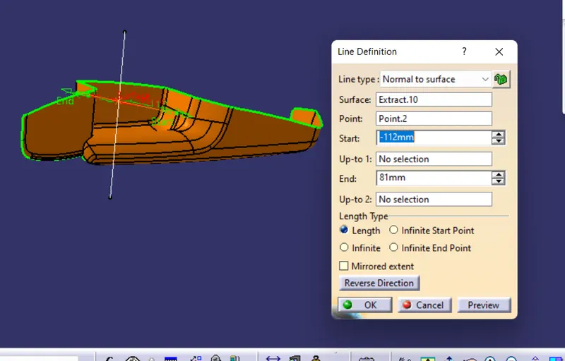
for creating main tooling axis first extracted the surface and created a point middle of it and created a line passing through this point and perpendicular to the surface this is out main tooling axis.
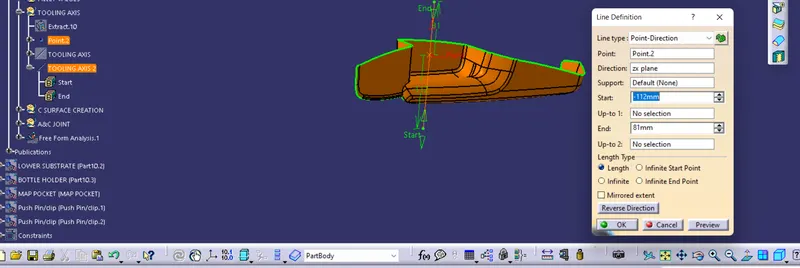
for creating side tooling axis used the same point and direction normal to the zx plane
- B-surface creation:
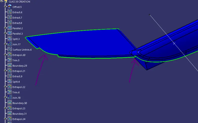
First i have offseted the given class a surface to 2.5mm inward direction. There were two patches missing i have resolved this patches by using multisection command and second patche we use jion command to remove subelement and then extact the nearby surface and extrapolet them and trimed, after this join these trimmed surface with offsetted one
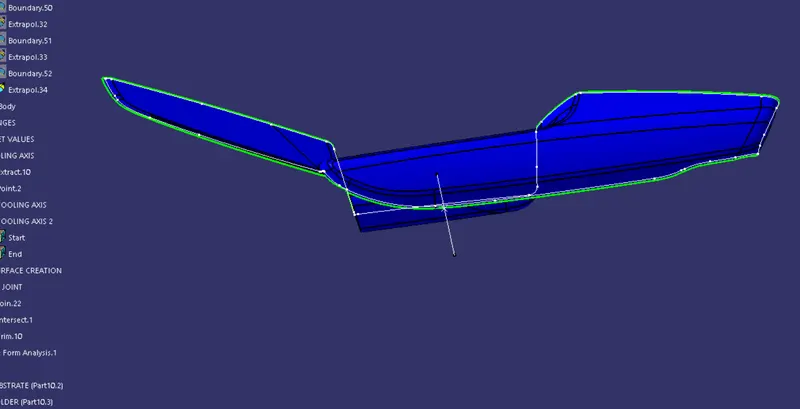
Final b surface:
- C surface creation:
Here first created a small small boundary on the class a surface and create a sweep along the direction of tooling axis where our surface edge is perpendicular to the tooling axis, and sweep perpendicular to the surface where the surfacew edge is along the tooling axis. joint all the c surfaces together.
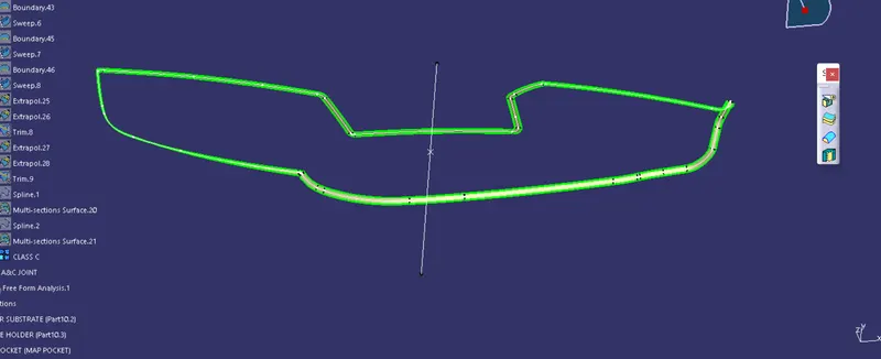
after creating c surface joint the class a and c surface together then unhide the b surface here b surface was not intersecting the c surface then after i extrapolated the b surface and checked the intersection the trimed the a&c surafce with the b here after this i checked whether our closed surface has a open surface or not with the boundary creation tool
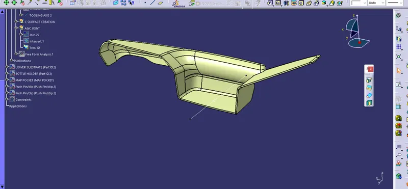
After making this go to part work bench and create a solid body
- FLANGE CREATION:
Used reference as a master section to create a flange first create a point beteween the two line of heat steakes and make a plane normal to zx plane
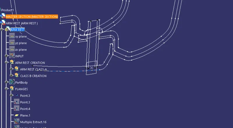
taken multiple extract of the side edges and make intersetion line between a plane and multisection for obtaine a point in side edge of the part now go to sketche and projrct a line from the master section and asolate it and the make coincidence this line with intersection and Projrct all the necessery line from the master sectioon and trim.
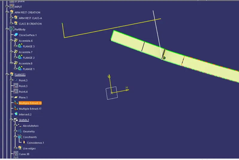
created a multiple extract of the line which is below the extracted surfaces, using thise line as a guide curve and profile as a extracted line from the master section.
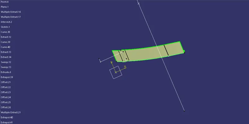
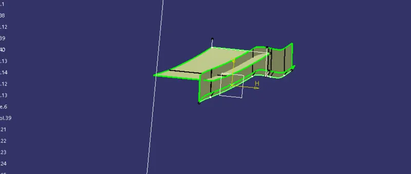
then create a surface perpendicular to this top surface to cut the soldi flanges
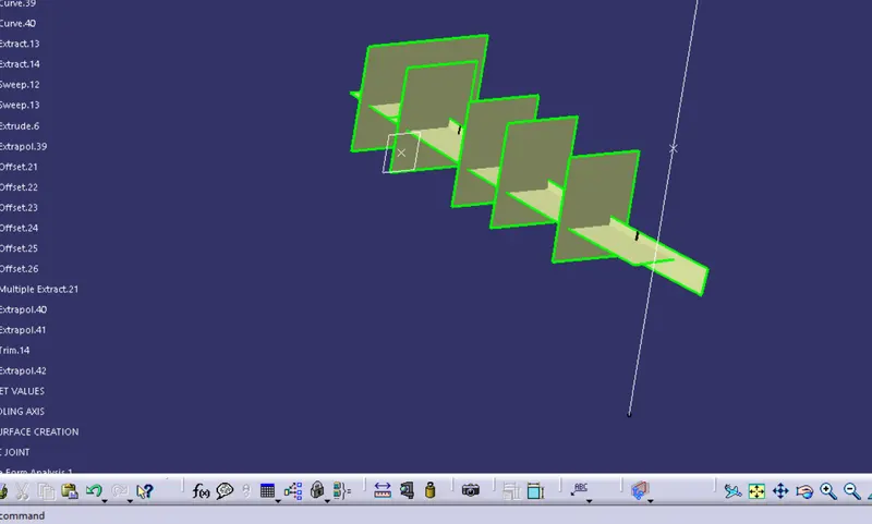
Now make a trim and then goto part workbence and thicken it to 2.5mm to create a solid body flange then split the flanges with this surface to get a flange
then create a hole in the middle of the flange and give the fillet on the flange as givem in the master section then used unio trim to
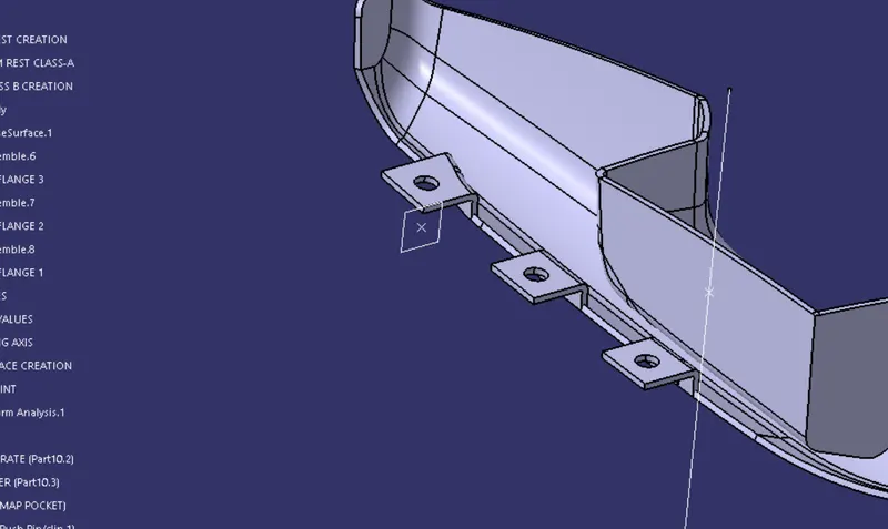
LOWER SUBSTRATE CREATION:
create A Point on the class a surface and a line normal to the zx plane. then create an offset of 2.5mm and this is our claas b surface
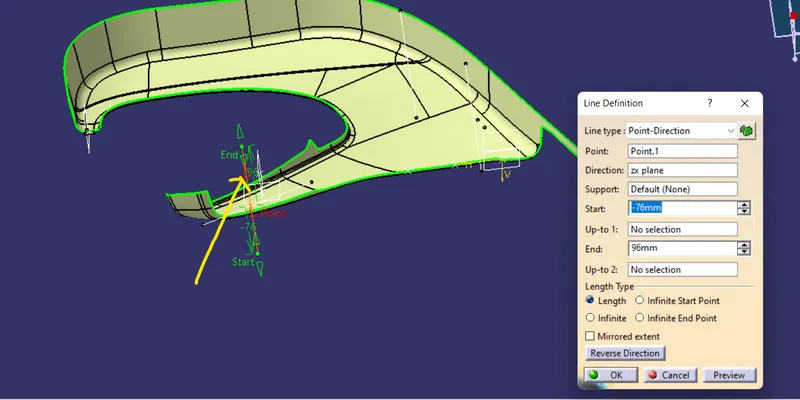
aftre offseting to 2.5mm there is no patches was removed so this is our final claas B surface
- C-SURFACE CFREATION:
First created a small small boundary on the class a surface and then sweep with reference surface 90 degree to class a surface
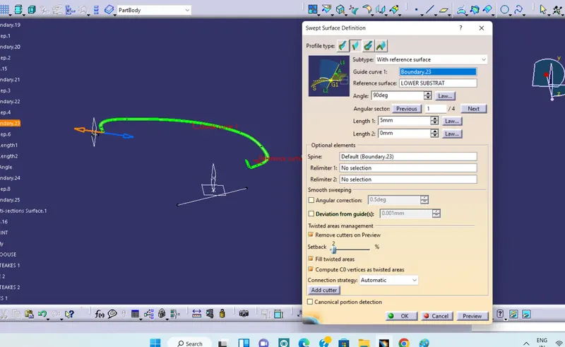
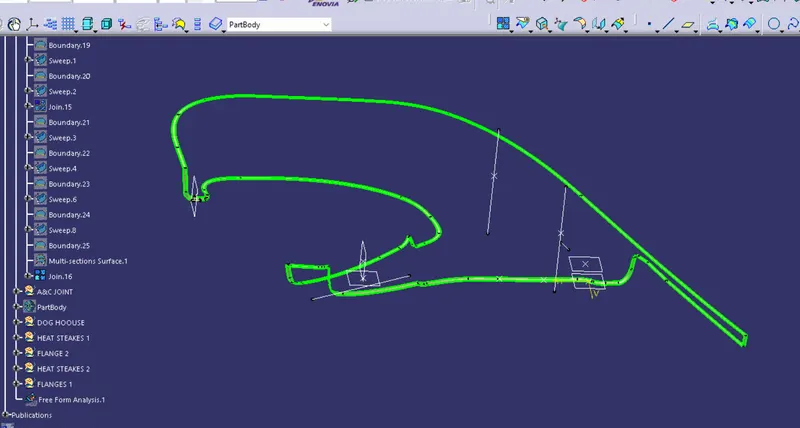
then joint all the sweeps together to get a class c surface then joint class a with class c surface to get final classA AND C
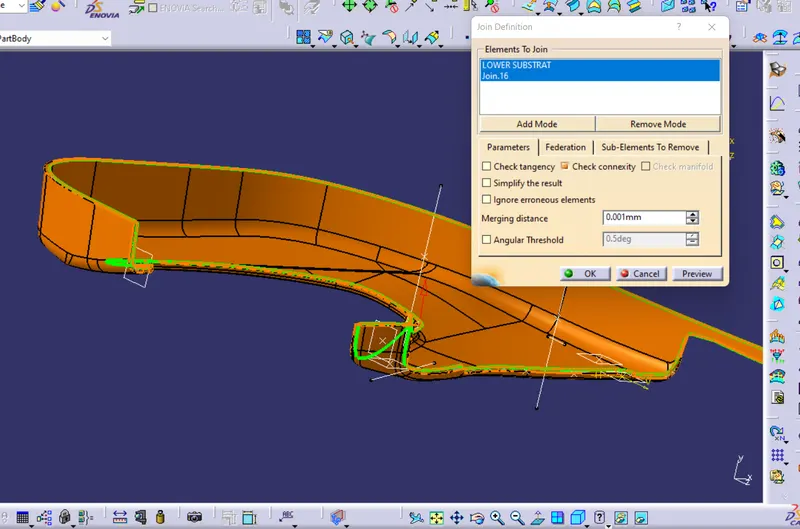
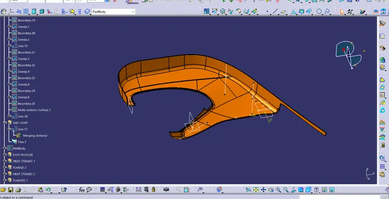
then try to check whether your boundary is closed or not, try to create a boundary on it if boundary doesent create then your surface is fully closed
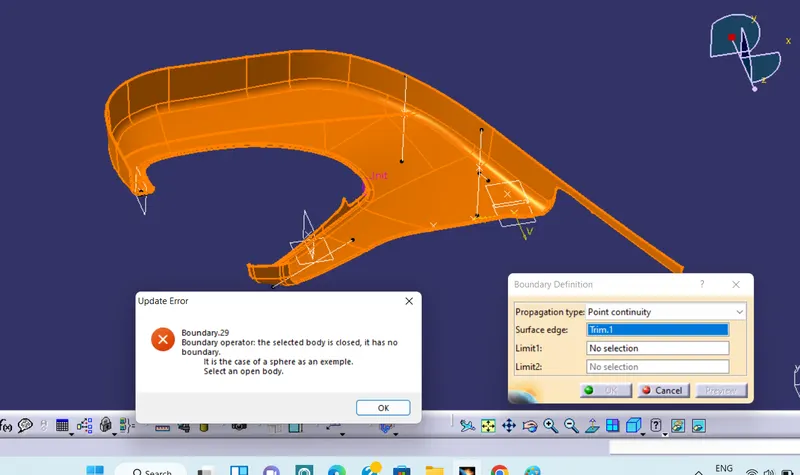
Go to part workbench to create a solid body.
- HEAT STEAKES CREATION:
First Created a point between the two lines of master section of Heat steakes and then create a plane 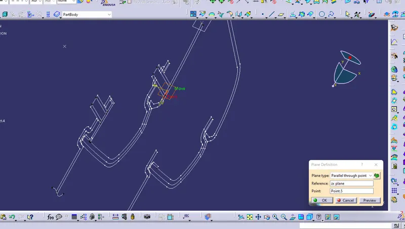
then go to sketch workbench and create two circles and come to part work bench and the pad it at a height as given in master section
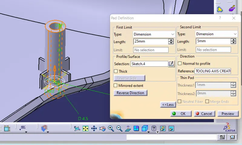
- RIB CREATION:
For rib creation again go to another sketch and creat two crosss line (each 15 mm) perpendicular to each other the then go to part workbench and pad it and give thick and Neutral fiber.
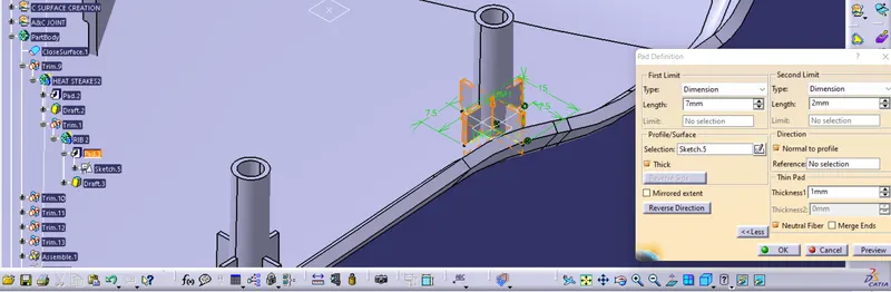
after rib creation done a union trim with the heat steakes and after used union trim for heat steakes with the main part body.
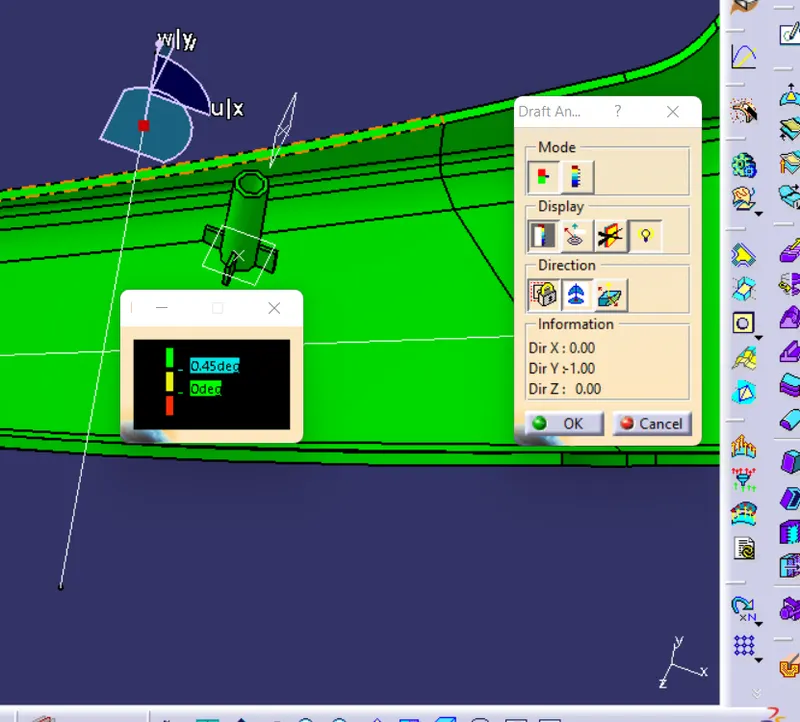
- DRAFT ANALYSIS FOR Heat steakes:
Here the draft analysis is created with thw main tooling axis. For Draft analysis got o Customized view parameter and change the part to material mode and go t draft analysis and pick on the compass and drag it to the side tooling axis and lock it and click on the Heat Steakes, here Green colore shows as the draft angle greater thane 0.45 degree and in between 0 to 0.45 degree it shows with blue colore and les than 0 degree is showing with red colored. Hence we clear with the side coring as draft.
- DOG HOUSE CREATION:
First create a pont and a plane along zx and go to sketch and create 25 mm squqre and then pad it along the direction of main tooling axis to a length of 30 mm and back side of 7mm afteer give a draft of 1.5 mm in three sides , and give neutral element as aplane and pooling direction as a tooling axis
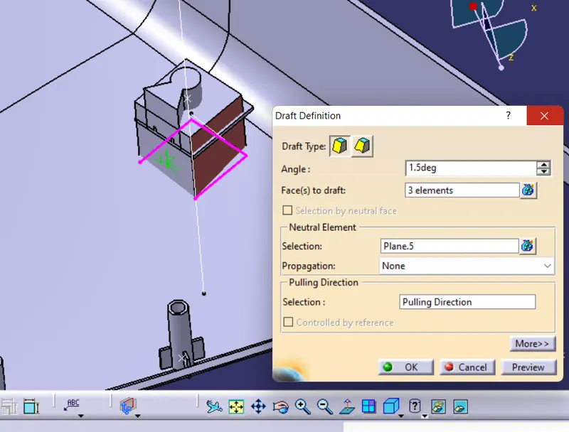
Now use shell to a thickness of 2.5mm, Now again give draft of 0.5mm for side coring.
Now taken an extract of inside wall of dog house and extract of main body now off set the surface off main body towards top at a distance of 5 mm then taken an intersection between the dog house extracted surface and offseted surface we get a line now extrud this line and trim with the side wall surface and offset to outward to a value of 0.4*t and Hide all the remaining Surface perform an extrapolat on the offseted surface. Now go to part workbench and split dog house with the surface this is done to avoide Sink mark on the part body. In my Dog house creation the Sink mark saver Height is not in the range of 3-6mm it is 7mm at the fron and 2.8 mm at the back, this is much of height variation came due to not flat surface at the part, it is too much curvy
Now create an rib on the dog house for this go to sketch draw a sketch as per given dimensions and then come to partworkbench and pad it and perform Bolean Operation to assamble it with the dog house.
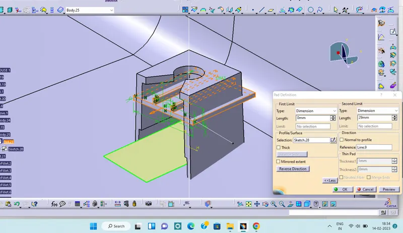
Give draft of 0.5degree at the rib, choose elements to draft as parallel to seide coring and draft on the dog house splitted area.
Now create a Push pin hole on the top of the dog house, Draw a sketch as per given and Pad it and use Boolean opration as a Remove.
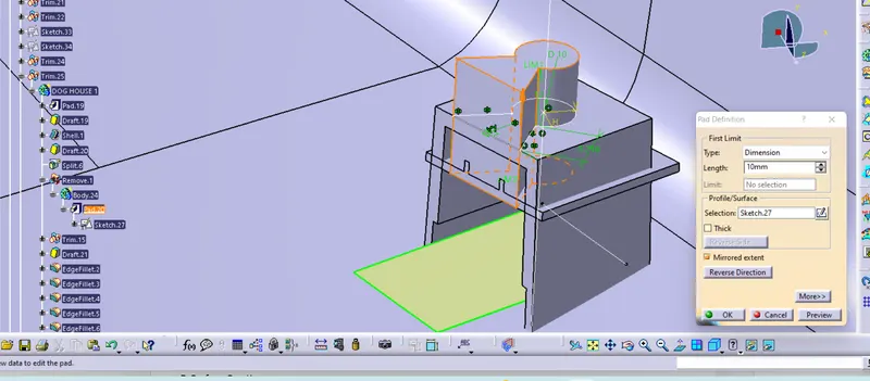
Now Copy the dog house and paste it in the same lower substrate part and the translate it at a point where you want .
- DRAFT ANALYSIS FOR DOG HOUSE:
For draft Analysis first we created a tooling axis as pint and direction direction taken as normal to the front face of the dog house
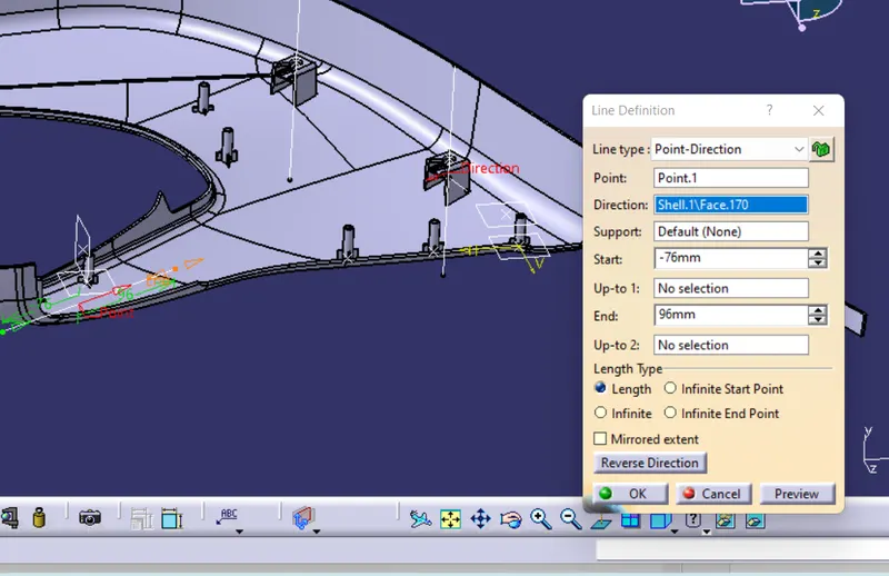
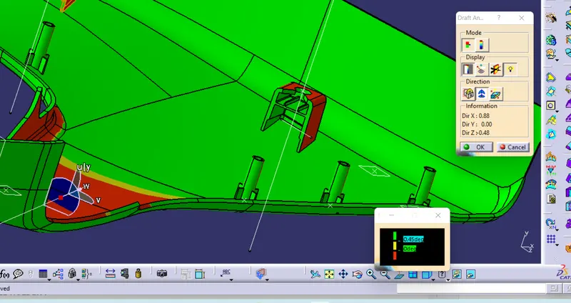
For Draft analysis got o Customized view parameter and change the part to material mode and go t draft analysis and pick on the compass and drag it to the side tooling axis and lock it and click on the dog house, here Green colore shows as the draft angle greater thane 0.45 degree and in between 0 to 0.45 degree it shows with blue colore and les than 0 degree is showing with red colored. Hence we clear with the side coring as draft.
BOTTLE HOLDER :
- TOOLING AXIS:
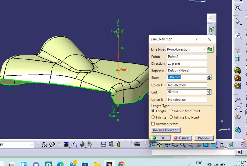
first create a point on the surface of the part and make a line Normal to ZX plane fig
- B-Surface Creation:
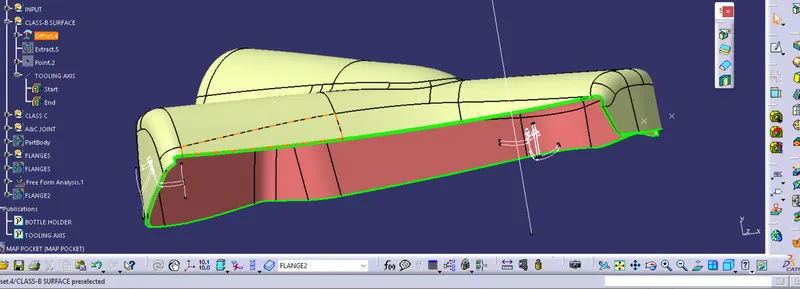
Offset the Class A Surface to outward direction at a Distance of 2.5mm here no any patches removed after offsetting
- C-Surface Creation
Unhide the Class A and Create a small small boundary and use sweep as with reference surface at a length of 5mm Fig
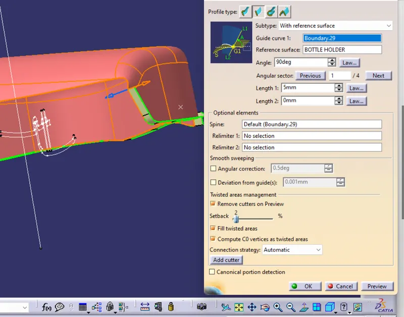
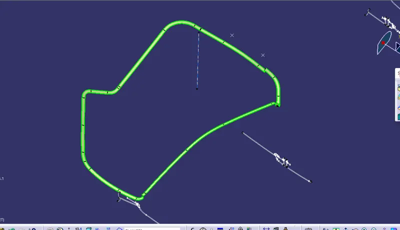
Joint all the C surface together and join again the c surface with the Class A Surface
Now Unhide the class B surface and perform an intersection to see your Class A &C and B surface are perfectly intersect or not if intersec then use trim command to obtaine final closed surface
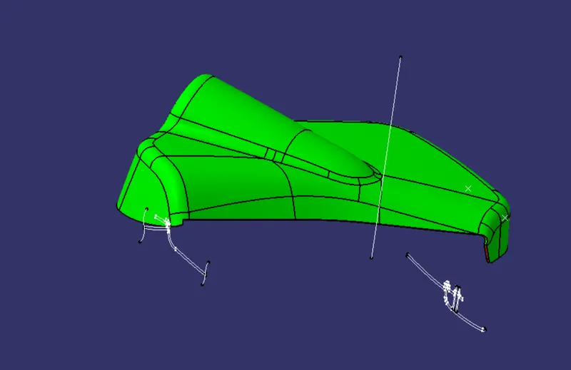
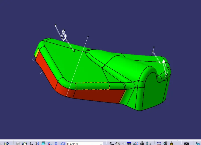
this is our closed surface, after draft analysis one side is not clearing as CLASS A was not also clearing.
then try to check whether your boundary is closed or not, try to create a boundary on it if boundary doesent create then your surface is fully closed
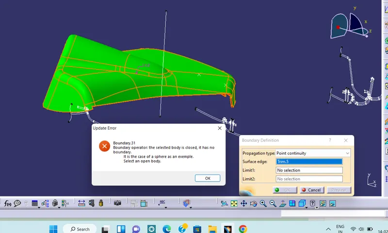
Now go to partworkbench and create solid
- FLANGE CREATION:
Used reference as a master section to create a flange first create a point beteween the two line of heat steakes and make a plane normal to zx plane
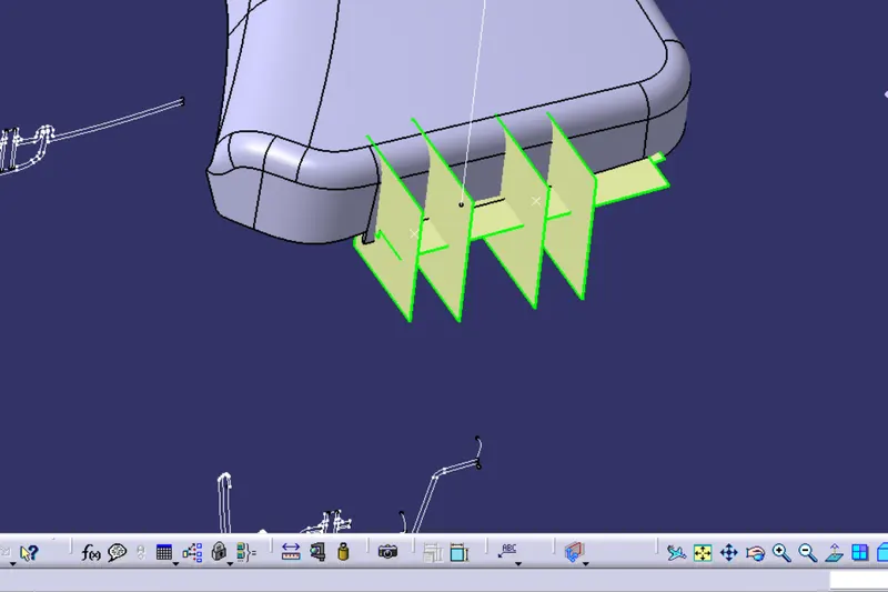
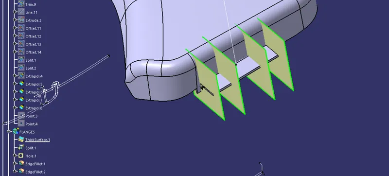
Here we split the flange as cuuting element surface. After creating flange make a hole on the flange and create a centre pont on the hole.
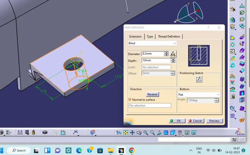
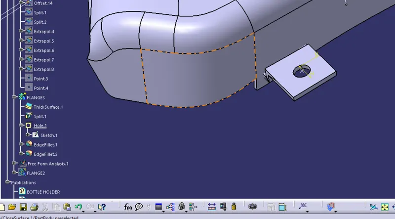
Now for insert a heat steakes in the hole, copy the heat steakes and paste it onthe same Geometrical set now translate the Heat steakes point to point select first point as the origine and second point where you want to move like in flanges.
MAP POCKET CREATION:
- TOOLING AXIS CREATION:
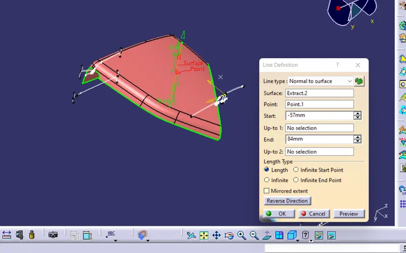
First create a point on the surface of the part and make a line Normal to surface fig.
- B-Surface Creation:
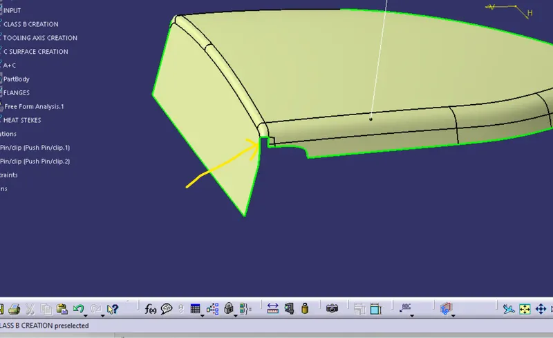
Offset the Class A Surface to inward direction at a Distance of 2.5mm here one patches fillet surface was removed after we use extrac, extrapolate and trim together and give fillet as same as offseted fillet
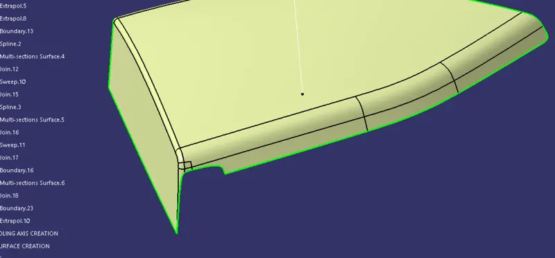
- C surface creation:
Here first created a small small boundary on the class a surface and create a sweep along the direction of tooling axis where our surface edge is perpendicular to the tooling axis, and sweep perpendicular to the surface where the surfacew edge is along the tooling axis. joint all the c surfaces together.
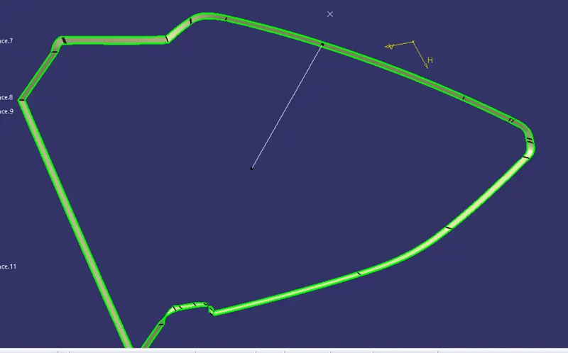
after creating c surface joint the class a and c surface together then unhide the b surface here b surface was not intersecting the c surface then after i extrapolated the b surface and checked the intersection the trimed the a&c surafce with the b here after this i checked whether our closed surface has a open surface or not with the boundary creation tool
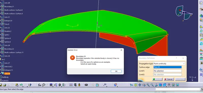
Now go to partworkbench and create solid.
- DRAFT ANALYSIS FOR:
For draft Analysis first we created a tooling whic is our main tooling axis in the direction normal to the surface of the body PART.
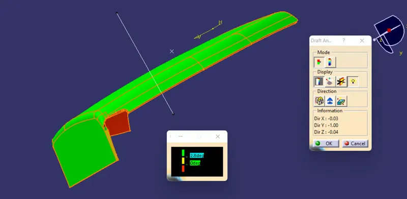
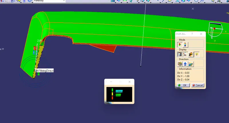
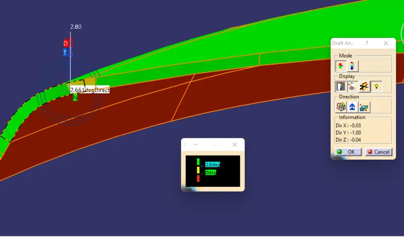
For Draft analysis got o Customized view parameter and change the part to material mode and go t draft analysis and pick on the compass and drag it to the side tooling axis and lock it and click on the part body, here Green colore shows as the draft angle greater thane 0.45 degree and in between 0 to 0.45 degree it shows with yellow color and les than 0 degree is showing with red colored. Hence we clear with the side coring as draft.
In two area where we get a draft of 2.47 degree as shown in below image in yellow color.
and one area where draft angle is 2.661 degree which is shown by yellow colour in the below image
- FLANGE CREATION:
Used reference as a master section to create a flange first create a point beteween the two line of heat steakes and make a plane normal to zx plane
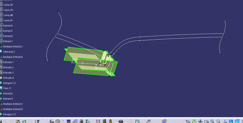
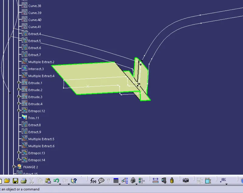
Before trim after trim
Go to partworkbench and thicken it to 2.5mm in downward direction
Here we split the flange as cuuting element surface. After creating flange make a hole on the flange and create a centre point on the hole.
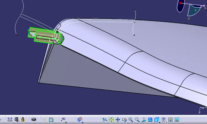
Now for insert a heat steakes in the hole, copy the heat steakes and paste it onthe same Geometrical set now translate the Heat steakes point to point select first point as the origine and second point where you want to move like in flanges.