Door Trim Lower Final project
Final Project
Aim: Creation of door panel parts in Catia V5 along with Draft Analysis, Tooling Direction, Class A, B and C Surfaces, closed surface and parting line for mold.
What is door inner panel?
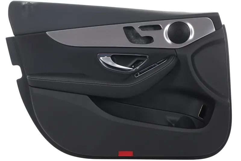
Door panel are used to give the aesthetic look to interior of the car and also it will cover the wiring and inner component of the car interior like speaker, window glass etc. Door panel consist of different parts such as lower substrate, upper substrate, garnish, bottle holder, arm rest etc., which give looks to interior, fulfill the comfort requirement, hold the interior hidden parts and also hides the wiring of the car door panel.
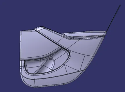
Our Door Panel:
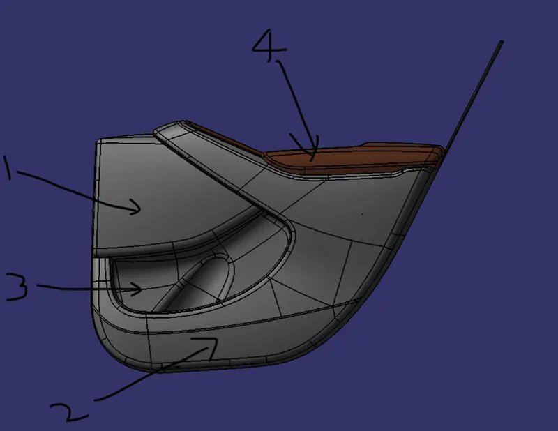
This is our door panel which we had created with given master section for the different parts.
- Upper substrate
- Lower substrate
- Bottle holder
- Arm rest
This are the parts we had designed and material are given to it. We had used our methodology that we had learned previously to create this door inner panel.
We were provided with this class A surfaces and master sections from this we created the solid bodies followed by master sections.
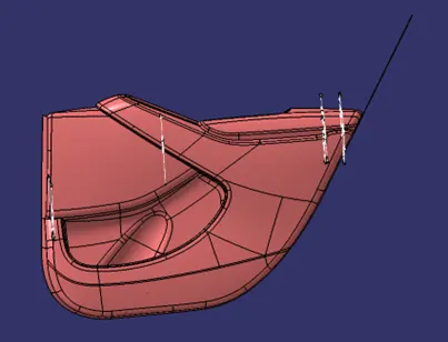
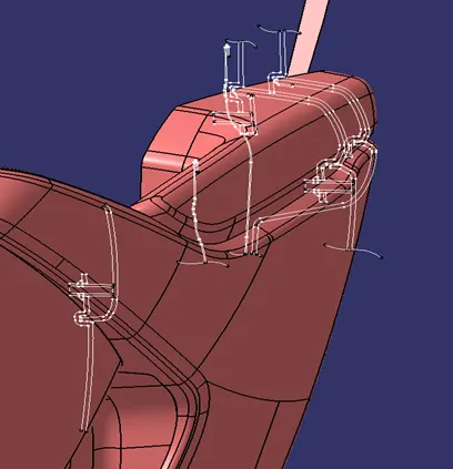
Designing Arm Rest:
We start with the arm rest, so first we copy and paste the surface with result link in separate geometric set or separate part bodies.
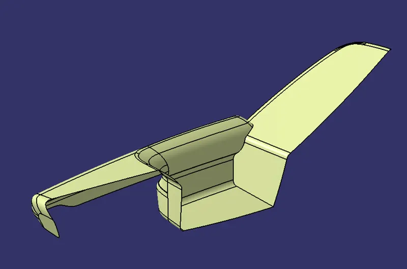
After copying and pasting the arm rest surface first thing we will do is the tooling direction and do the draft analysis of the surface.
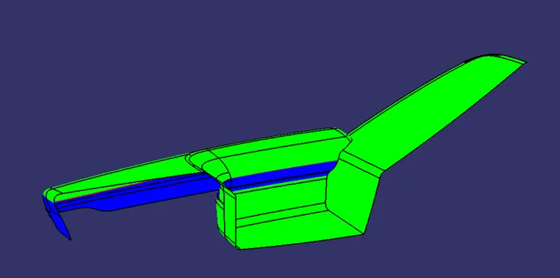
Some surfaces are folded inside so we will need a side core for the creation of this kind of surfaces we need side mold for the creation of the model. Now we will create the class B surface by creating off-set of 2.5mm as it was taken from the master-section that is provided with the main surface.
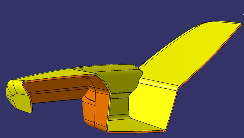
The yellow color is the class A surface and the orange is class B surface which is off-set to 2.5mm from class A. We do had some irregular surfaces to fix which we did fix using multi-section solid and Fill command. After creating the class B surface we had to extrapolate the surface so that we can make a trim between class C and Class B surface. Now we created the class C surface in multiple parts and then join them. As the boundary had so many turns and fillets, we had to create the class C surface in parts and then join them together.
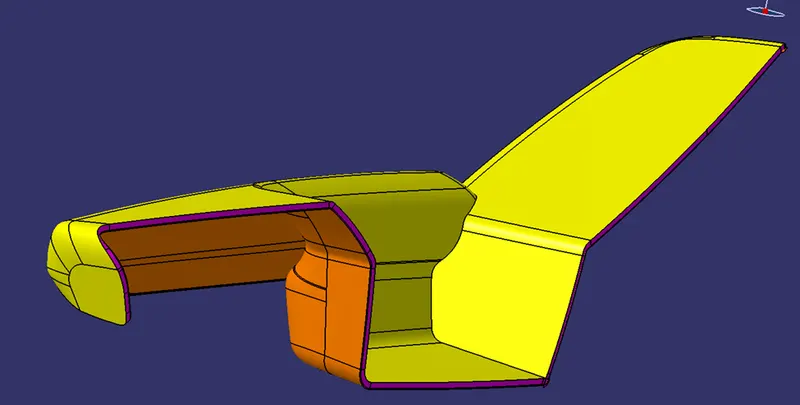
In the above image yellow is class A surface, orange is class B surface and purple is class C surface. Now we create a closed body and then perform draft analysis on the same.
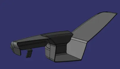
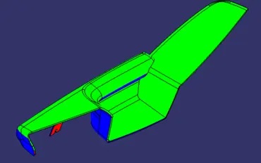
Image on left is solid body with class B Feature and image on right is Draft Analysis which is exactly same as class A Draft Analysis. So, we need some side core for creation of this kind of surface.
Upper Substrate:
Class A Surface and Draft Analysis.
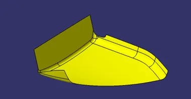
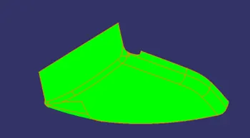
Class B and Class C Surfaces
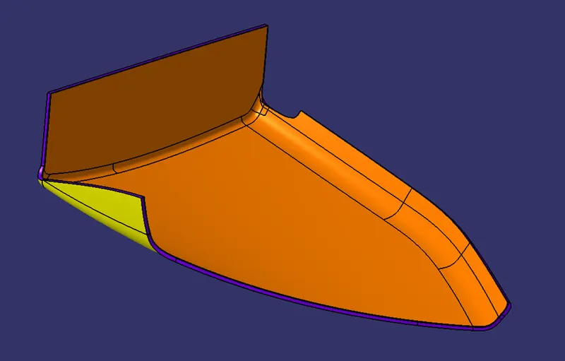
Solid Surface and Draft Analysis.
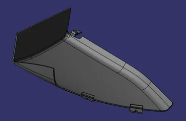
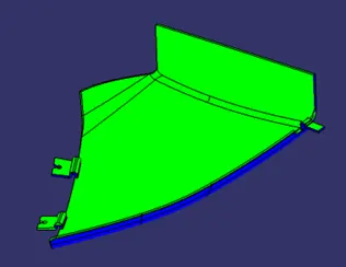
Bottle Holder:
Class A Surface and Draft Analysis.

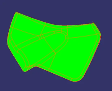
Class A Class B and Class C Surfaces
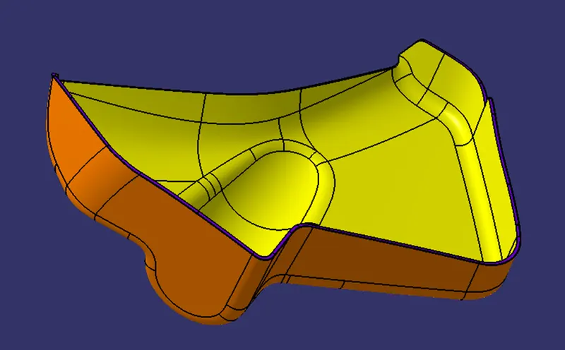
Closed Solid Surface and Draft Analysis.
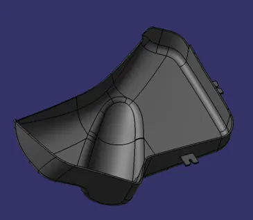
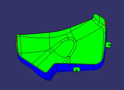
Lower Substrate:
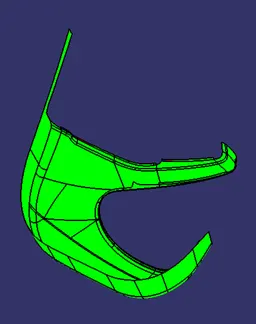
Class A surface and Draft Analysis.
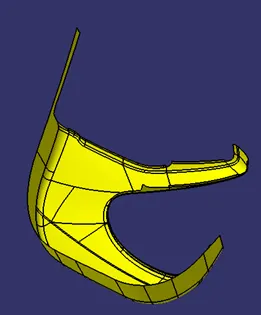
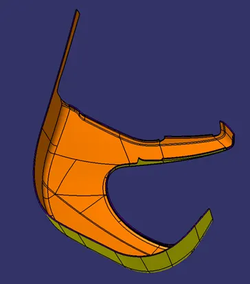
Class A, Class B and Class C Surfaces.
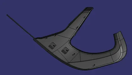
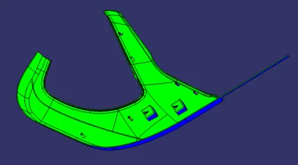
 Closed Solid Surface and Draft analysis.
Class B Feature Dog House:
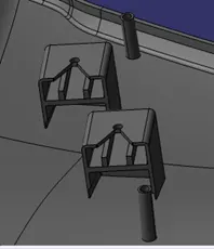
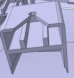
Dog house is a feature that is used to clamp two surfaces with push pins and different material this is created with a specific given dimension which is shown in the image below.
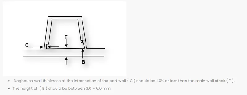
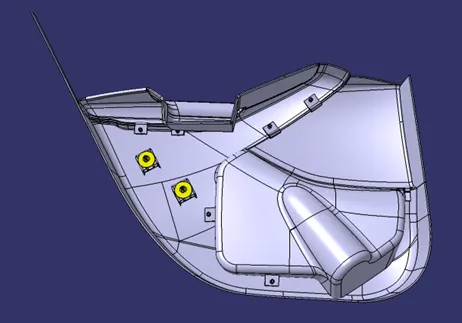
This are the parameters that has been used to create the class B feature Dog house on the Lower Substrate of the model so that we can clamp the other surfaces to the lower substrate using push pins. In our model we had taken the thickness is 3mm because only two of the Doghouse will pe holding the entire panel so, we increase the thickness in order to withstand the stress.
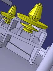
We can see the ribs are created inside the Doghouse; this are created to hold the push pins base.
Class B Feature Heat Steaks:
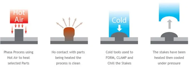
Heat steaks are the feature which are used to join the two parts together. This is a permanent joint and is done by heat treatment. The heat steaks are given the draft of 0.5° because it is maximum prescribed. This heat steaks will join the Lower Substrate with Arm Rest, Arm Rest Garnish, Upper Substrate and Bottle Holder.
Assembly:
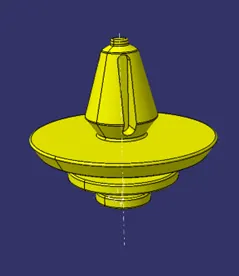
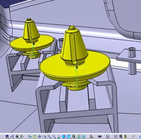
The assembly of the above surface is created with all the above plastic bodies and adding the push pins to the dog-house.
The technical assembly is done by creating the Axis line in circular part and Doghouse and creating axis at the center of the bottom or top plane. (as required for assembly). Then we do axis constrain and then offset constrain with axis plane as reference so that it won’t be directly related with the part body.
Conclusion:
Finally the assembly and all the door lower trim part are created by following the master section and are passed through the Draft analysis also. Now this part can be send to manufacture.