Week 11 - Final project
DEVELOPMENT OF DOOR TRIM PANEL
SCOPE:
To design and development of vehicle interior door trim using given class A surface along with master section. Also create the side attachment features as per design rules.
OBJECTIVE:
- Creating a product file with all the parts
- Creation of tooling direction
- Creation of close surface
- Following master section
- Creation of additional engineering features
- Report writing and file attachment
INTRODUCTION:
Door panels serve as an interface between the interior of the car and the inner workings of the door, and between vehicle occupants and the door. They are expected to meet a variety of design specifications regarding safety, aesthetics, and functionality. Generally, the door panel is divided into two parts of easy designing like arm rest, map pocket, lower substrate, bottle holder, these requires one of the toughest requirements among the interior parts of the car. This should be designed to with stand the load while being less than 2mm in the thickness and also protect the occupants during collisions. Door currently has an inner full width panel consisting of electronic windows. Central locking system and speakers. These panels typically consist of a covered with either textiles or plastics.
A surface:
A surface is the styling surface that is visible to the consumer and gives an aesthetic look for the model designed. Engineering features are not added to this surface. Class A is any of set freedom surface high efficiency and quality. Although strictly it is nothing more than surface have curvature and tangency alignment.
B Surface:
Class B surfaces are the secondary surfaces that you can see sometimes includes all the engineering features such as dog house, locators, ribs, flanges, etc. This surface is the direct offset of the Class A surface which gives thickness to the component.
C Surface:
This surface is the combination of the Class A and Class B surfaces also they are the backside surfaces that can have tool marks, flash, and other imperfections without hurting appearance, function, etc.
B- side Features:
Rib:
The ribs provide economical stiffness and strength to the part without increasing the overall thickness of the part.
Boss:
Bosses are used to facilitate the registration of mating parts, for attaching fasteners such as screws, or for accepting threaded inserts.
Heat stakes:
Heat Staking is a pulsed-heat process to join two or more parts out of which one at least is made of plastic. The process is to deform the plastic material using heat and force at a set process time. The bond is made by partially de-forming the plastic part in order to fix the other.
Dog House:
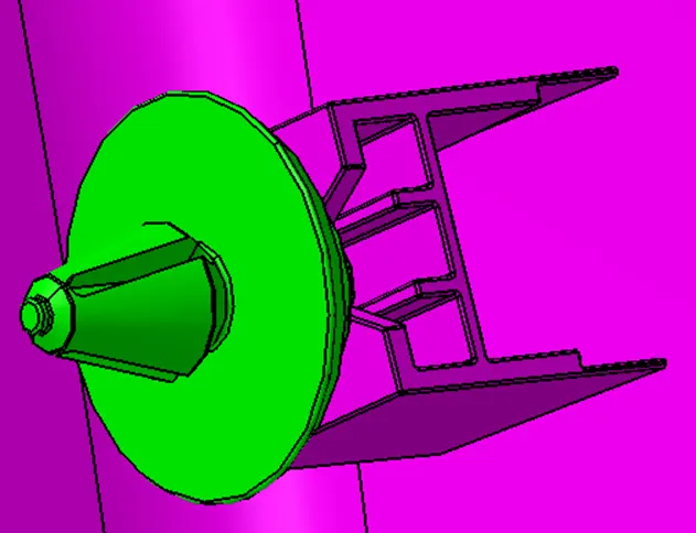
Dog house is the attachment feature which helps you to assemble things at certain heights and also resolve the plastic defects. There is plenty dog house design which can be used for assembly purpose but we will be using the one provided to us by the resources.
Flanges:
These flanges will be built on the components for the fitment purpose with lower substrate. The hole at centre will be guided along the heat stakes. Later top portion of the heat stake will be melted over it. The flange should rest on the supporting ribs on side.
Push Pin:
These pins are used for the assembly purpose. These pins are guided into the sheet metal body. The pin is assembled over the dog house on one side and other into sheet metal.
Given input study:
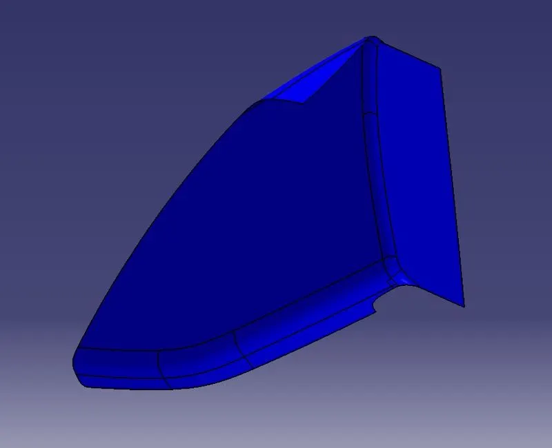
Door trim panel without master section
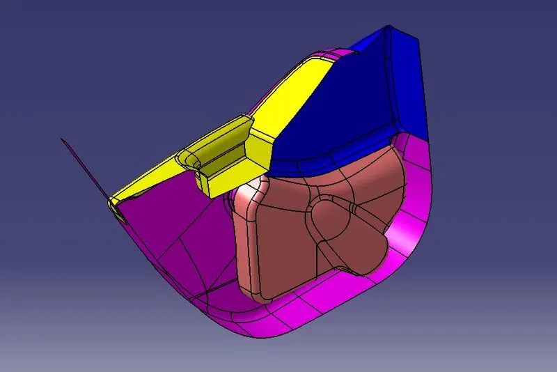
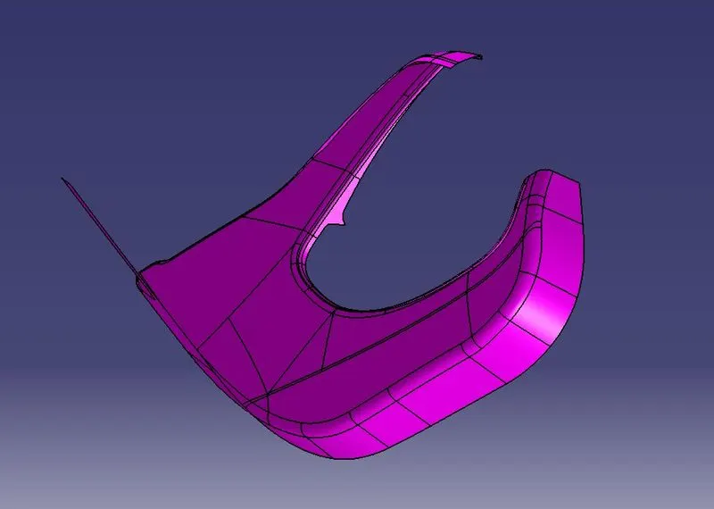
Door trim panel with master section
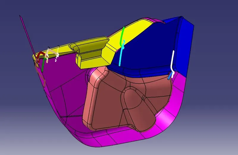
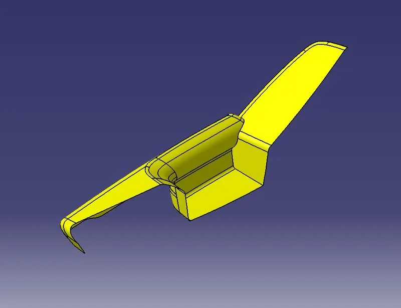
Door Arm Rest:
In the front of the car, a central armrest, which commonly folds away based on user preference, will also often include a storage compartment and sometimes even cup holders. Some also provide the location for controls for non-essential functions of the vehicle, such as climate control or window motors.
Map Pocket:
Map pockets can be created integrally within the door trim panel by forming a projection region outwardly towards the passenger compartment and then providing a separate panel attached to the rear outboard surface of the trim panel. This type of map pocket protrudes into the passenger compartment. Another type of map pocket such as a recessed map pocket can also be formed within the door assembly such that the storage compartment of the map pocket is generally located between the trim panel and the outer metal panel of the vehicle door. An aperture in the door trim panel defines the opening into the map pocket. Generally, these types of map pockets are formed by a separate map pocket assembly which is fastened to the rear surface of the trim panel. The map pocket assembly includes a front portion and a separate rear portion which are connected together to form the map pocket assembly and define the storage compartment. The rear portion defines a rear wall of the map pocket assembly. The front portion defines a lower front wall and a pair of side walls. The region above the lower front wall is generally open to provide access to the storage compartment of the map pocket. The map pocket assembly is then attached to the rear surface of the door trim panel such that the opening of the map pocket is generally aligned with an opening formed in the door trim panel.
Lower map pocket
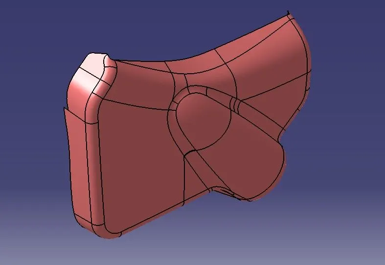
Upper map pocket
Lower Substrate
From the given input body thickness is measured
Thickness of all the component = 2.5 mm.
Draft angle for all component = 3°.
Calculations Based on component thickness
Boss calculation:
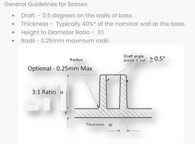
Wall Thickness t = 2.5mm
Screw boss thick =0.6*t=0.6*2.5
=1.5mm
Height: Diameter =3:1
H:7.5 =3:1
H =3*7.5
=22.5mm
Dog House Calculation:
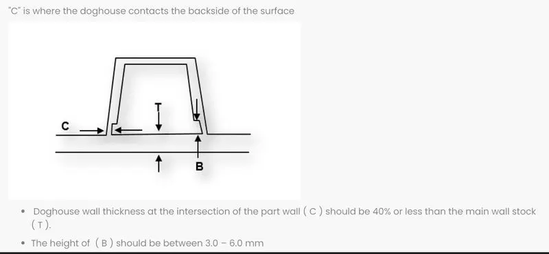
Thickness of Door Trim T =2.5mm
Thickness of Dog House =2.5mm
Dog house contact thickness C =0.4*T=0.4*2.5
=1mm
B =3 to 6mm
Rib calculation:
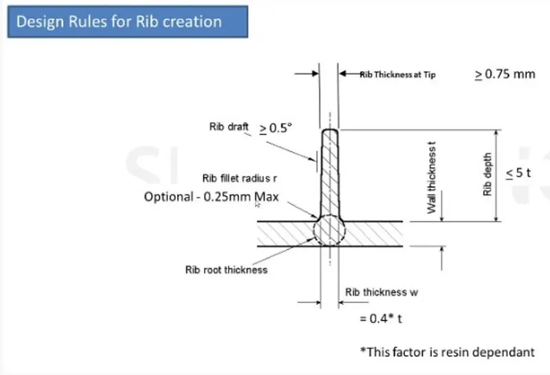
Wall Thickness = 2.5mm
Rib thickness = 0.4*t =0.4*2.5
=1mm
Rib Height =5t=5*2.5
=12.5mm
Rib fillet radius =0.125*t=0.125*2.5
=0.3125mm
Draft angle =0.5°
Distance B/W rib =2t=2*2.5
=5mm
Sequence followed to create the closed body parts are given below:
- Input checking
- Creating Tooling Axis
- Draft Analysis of Class A surface
- Creating Class B
- Creating Class C surface
- Class A + Class C
- Class A + Class B + Class C
- B-side features
- Draft Analysis of body
Input checking:
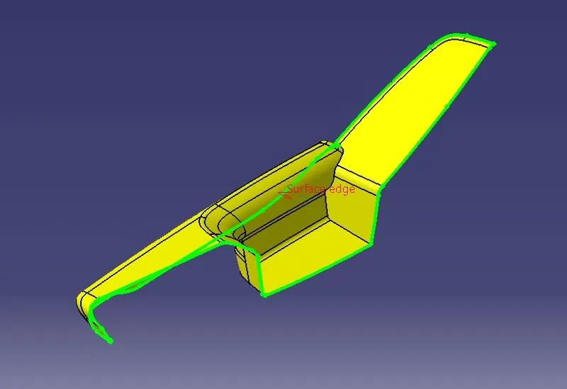
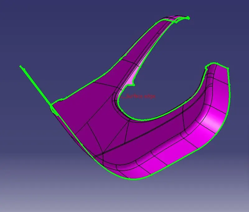
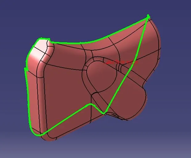
The given input surface is checked using boundary comment, the boundary of the class A surface is are fully closed or not. If there is any open boundary make sure close it properly.
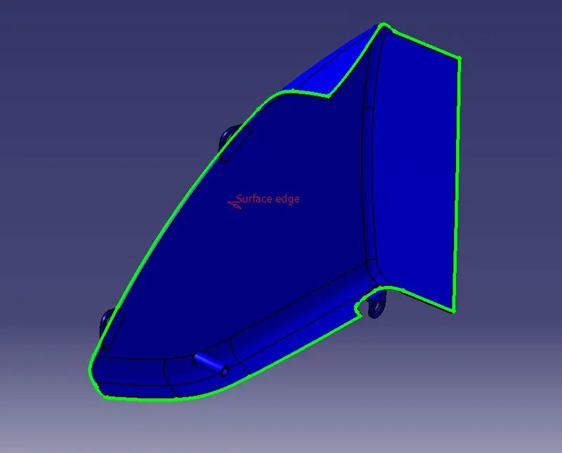
Creating Tooling Axis:
Tooling axis is the line represents the mold open and close direction at the time of component manufacturing.
If a component has flat surfaces, then the tooling axis identified by visually, otherwise intersection method is used to find the tooling axis of component.
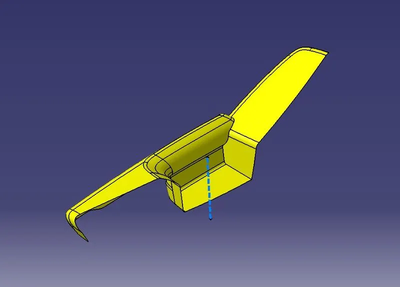
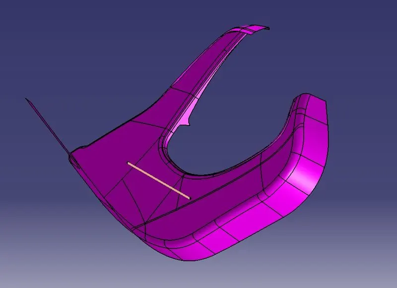
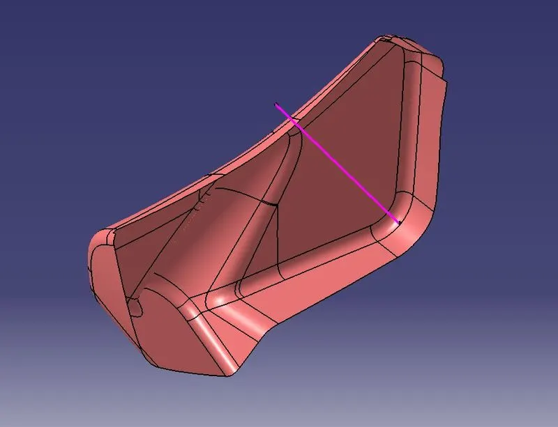
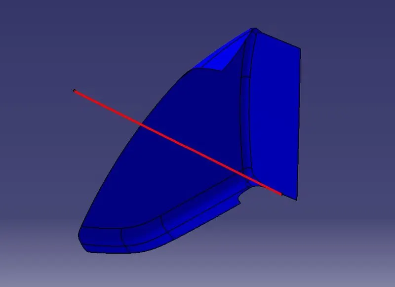
Draft Analysis of Class A surface:
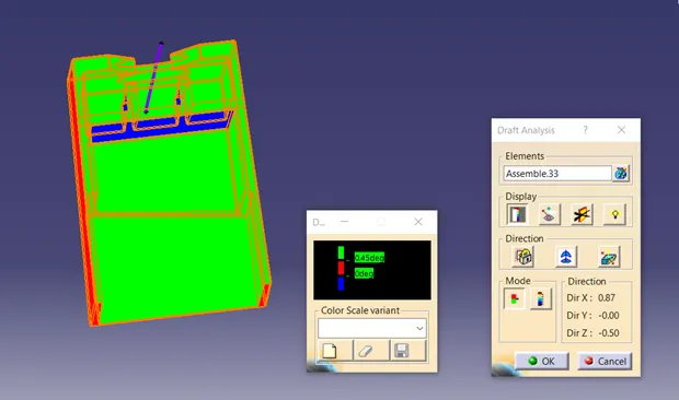
Drafting analysis shows that when component ejected from the mold die whether the component removed smoothly without creating any damage or scratch on the surface of the component.
The minimum draft angle applied on the component is 0.5°. But it need high precision and it increases cost of the mold.
In industry 3° draft angle is used for optimal solution for component ejection.
Here, draft analysis is done with respect to 3° angle.
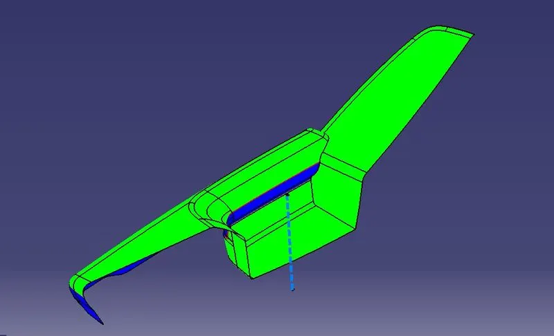
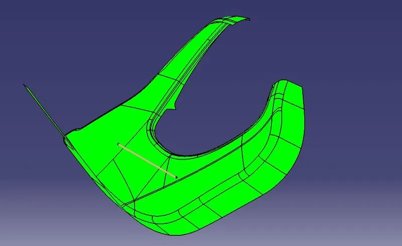
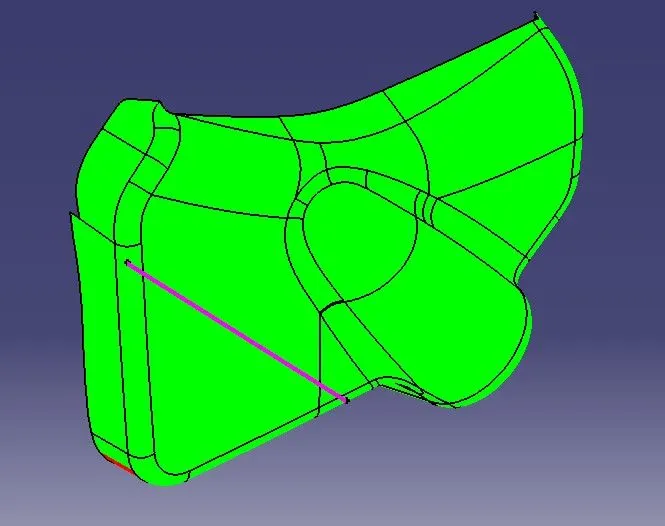
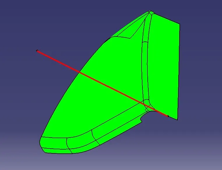
The green colour shows the given input class A surface has good positive draft effect. The red colour shows surfaces are not clearing mold ejection condition that means the given class A need modification for mold ejection.
Where modification of class A surface need to consider with customers.
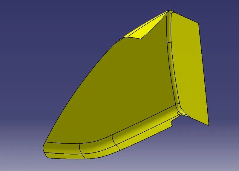
Creating Class B:
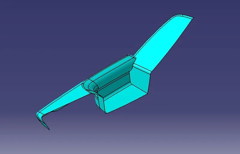
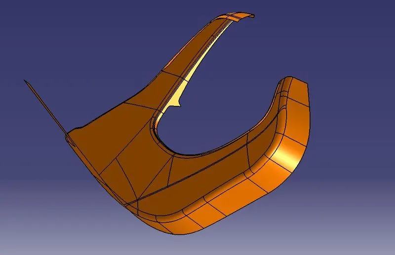
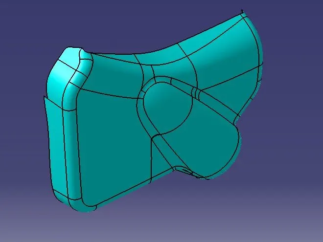
In here direct offset used to create the class B surface and done some patching work to complete the class B surface.
After offsetting the Class A surface 2.5mm, the patching work is done by using the sweep command.
Creating Class C surface:
- For creating class C surface, we have extracted the boundary of Class A using multi-extract and then converted to smooth curve.
- Now this smooth curve is swept along the draft direction with a 90deg perpendicular to CLASS A surface.
- In some places not smooth class C surfaces not formed, In those places multisection command used create the surface.
- Finally, the sweep surface and multisection surfaces are joined into single surface by join command.
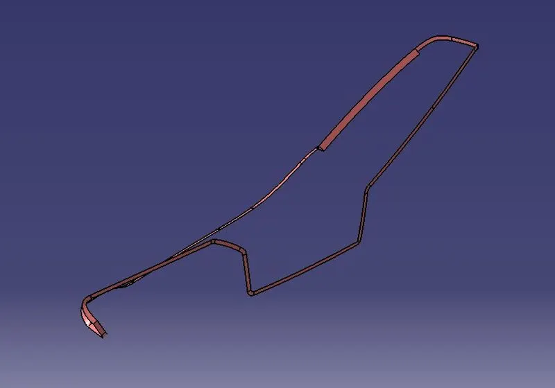
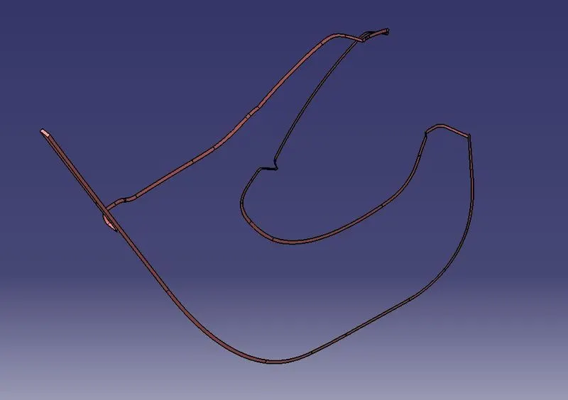
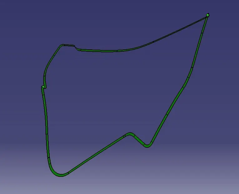
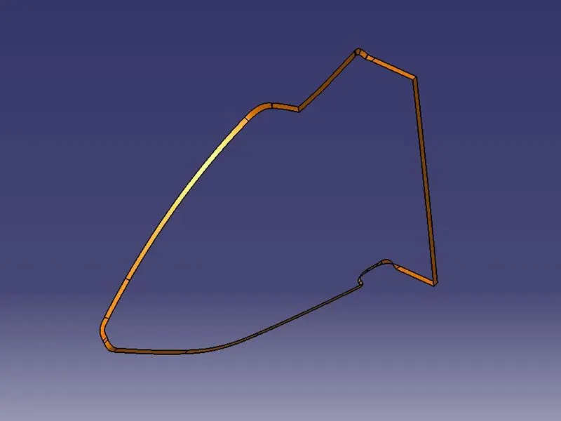
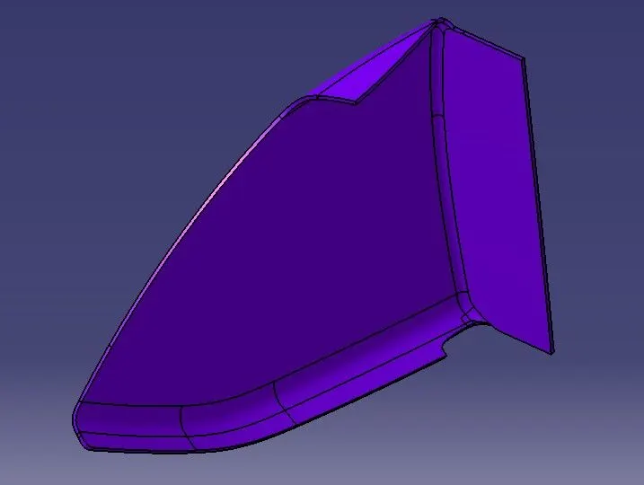
By, joining the class A and class C surface Class A + Class C formed for the final trim operation.
Class A + Class B + Class C:
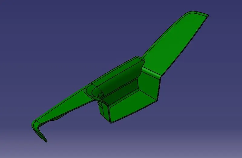
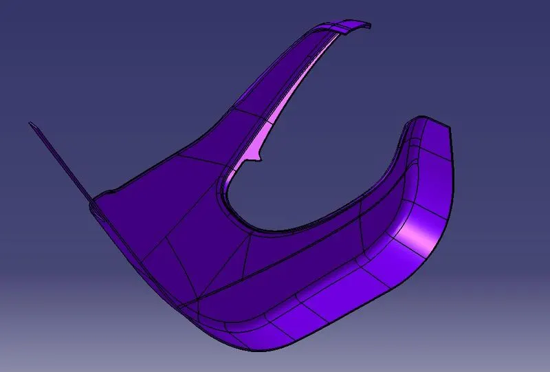
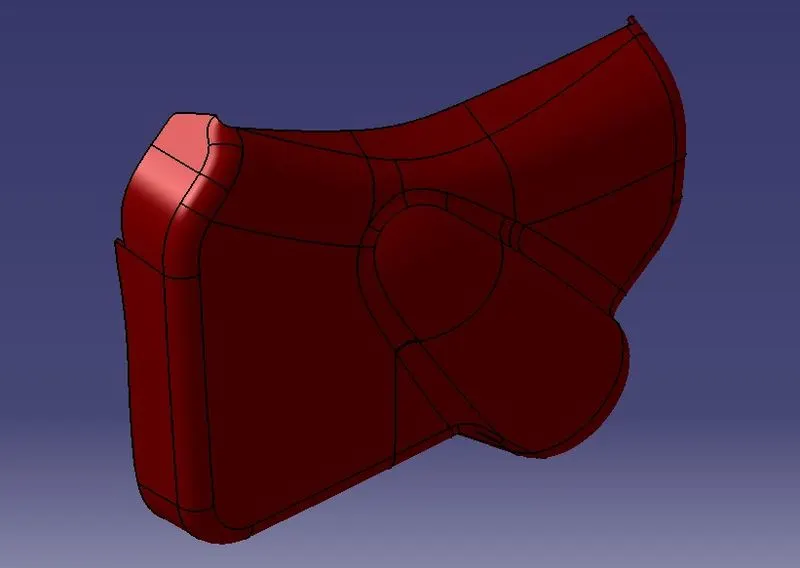
For this we have trimmed the Class B surface with Class A+C surface using trim feature. Then the fully closed surface is formed.
B-side features:
- B- side features are created as per the calculation dimension and applied draft of 0.5 °. All the features are applied with main body.
- Heat stake are used to locate the body constraint the Degree of freedom.
- Rib is created to reduce the stress level in body and acting as support for body.
- Apart from calculated dimensions all other dimensions are assumed.
Some of the connecting example position is shown below
Arm rest connecting with lower substrate
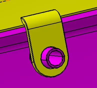
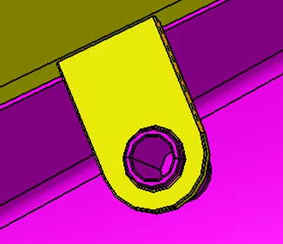
Lower map pocket connecting with lower substrate
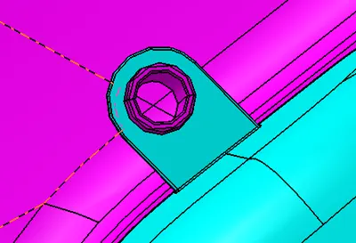
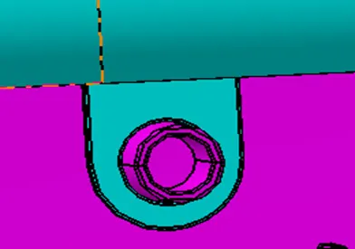
Lower map pocket connecting with upper map pocket
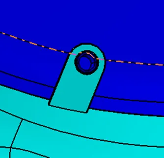
upper map pocket connecting with lower substrate
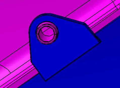
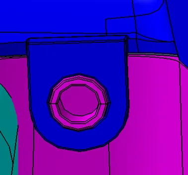
lower substrate dog house connected with push pin
Draft Analysis of body:
Draft analysis needed for every mold component because at the time of mold ejection the component removed without any difficulty or ejecting component should be safe without any crack and scratch on the surfaces with good aesthetics.
Here, Draft analysis done with respect to 3.
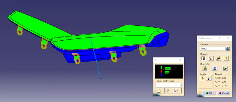
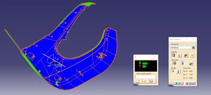
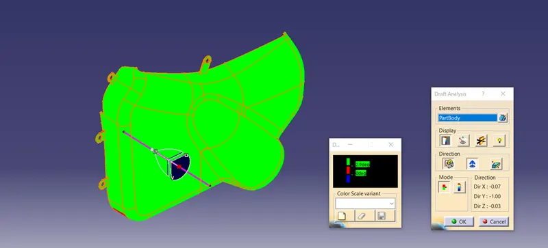
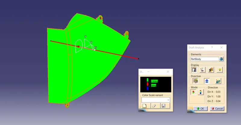
The above shown draft analysis is representing the closed body which has good quality at the time of mold ejection.
Green -positive draft - Accepted
Blue -negative draft - Accepted
Red -critical places - Not accepted
The surfaces shown in red colour are need to change draft to accepted range. If it is a class A surface before changing the surface shape need to consider with customer.
If it is a class C surface then angle changed to 93° or 87°. After changing the angle of the class C surface some places not meeting the draft condition. In those conditions are discussed with superior and left as it is.
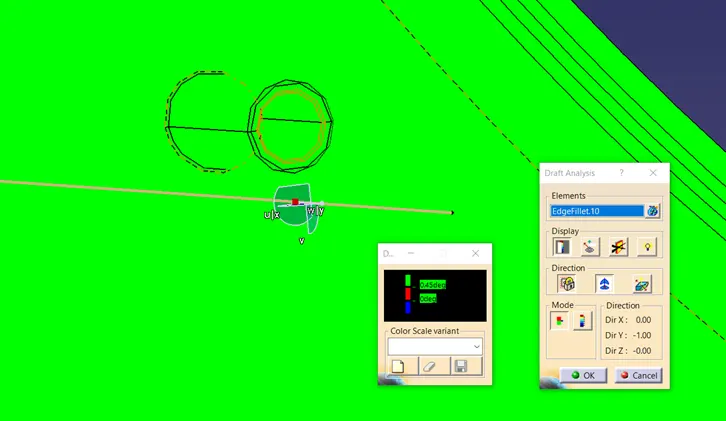
Heat stake drat analysis:
For heat stake 0.5° draft analysis applied all the places. Here shown one example only for reference.
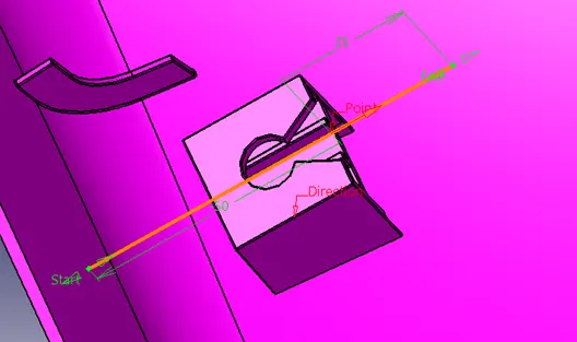
Dog house draft analysis:
The dog house is not in the direction of mold opening so mold split used. For that split need to create opening axis that is side core axis. Here side core axis created along dog house direction shown like below
outside draft analysis with respect to 1.5°
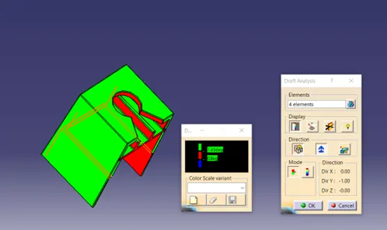
inside draft analysis with respect to 0.5°
Component views:
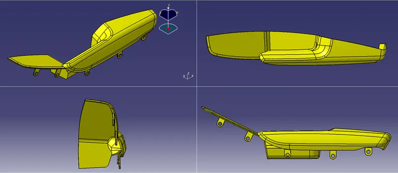
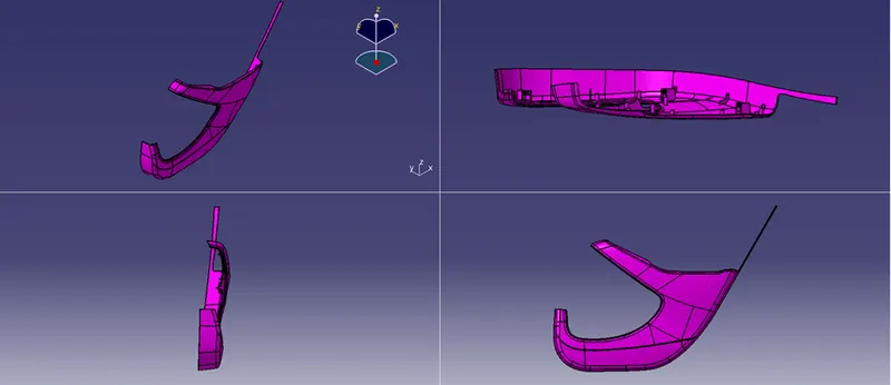
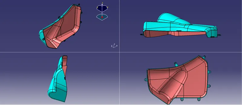
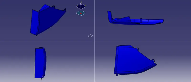
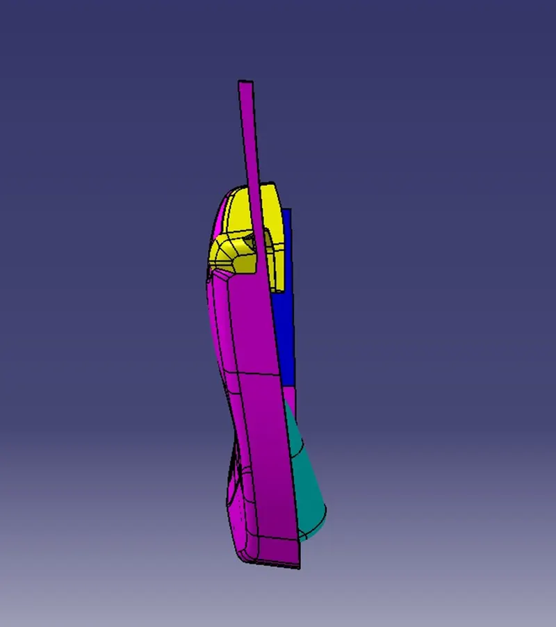
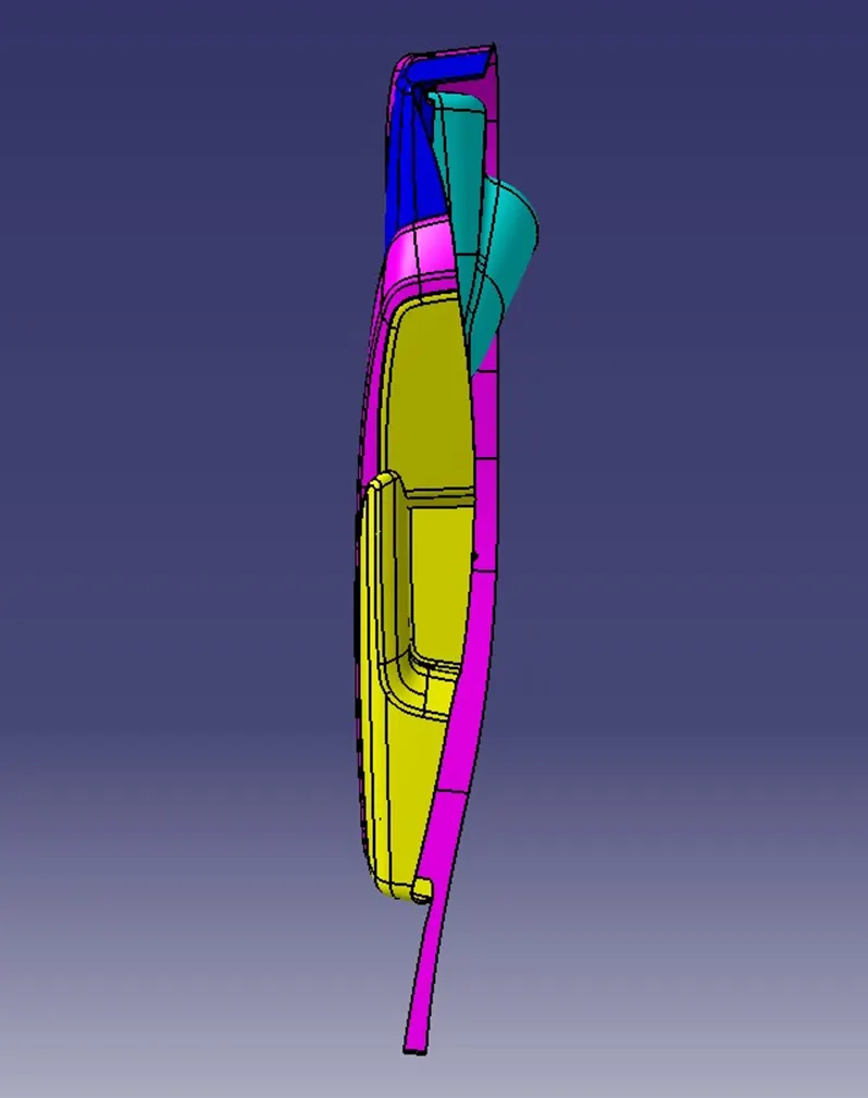
Door trim assembly:
Isometric View
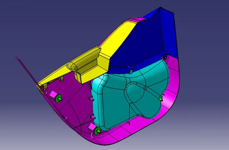
Front View
Top View
Right Side View
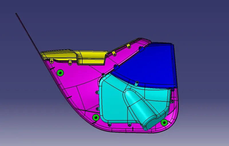
Left Side View
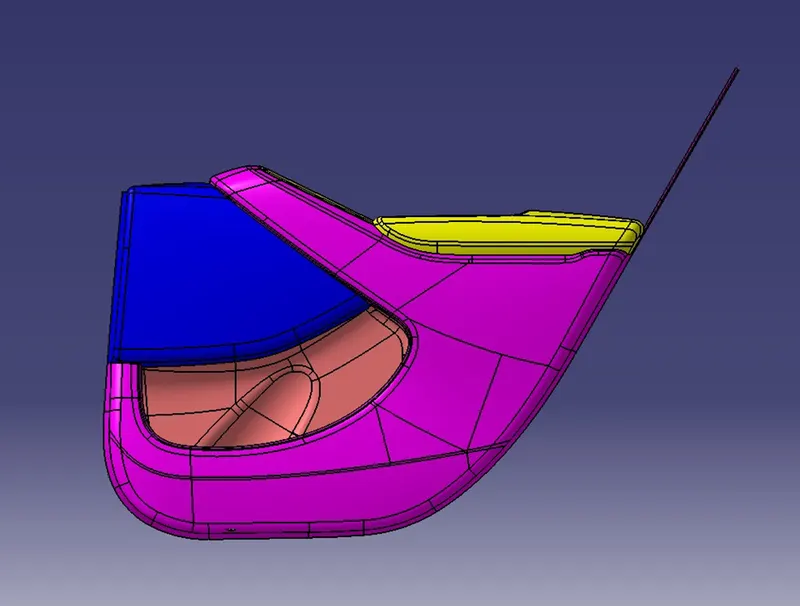
CONCLUSION:
The door panel successfully designed by following all design rules used in automotive industry. All the attachment feature are properly placed at different location.