Week 11 - Final project
Week 11 - Final project
OBJECTIVE :
The Objective of the project is to development of vehicle interior door trim panel by using CATIA V5 With given class-A surfaces of Arm Rest, Lower Substrate, Upper Map Pocket, Lower Map pocket along with the master section. Also Create the side attachment feature as per design rules.
- Analysing the class A and performing necessary modification to obtain the modified class A.
- Creating the tooling axis for all the components .
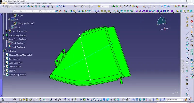
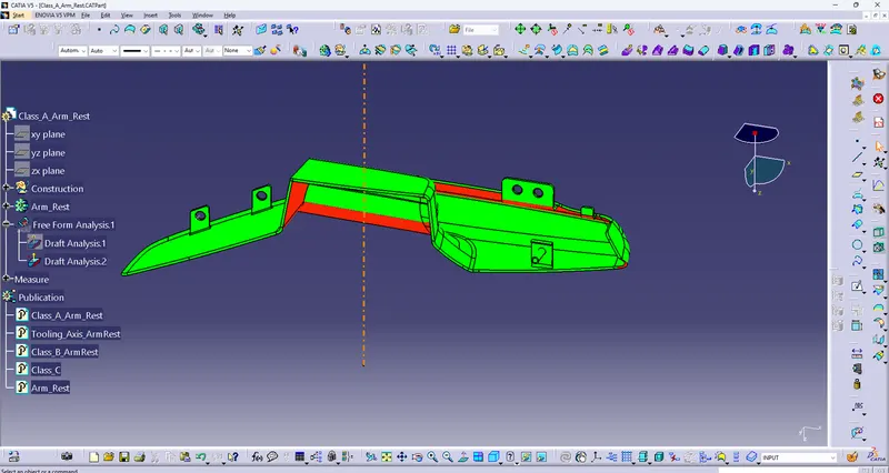
- Performing draft analysis of class A surface.
- Creating the class B surface with the help of surface workbench.
- Creating the class C surface with necessary draft.
- Trimming the CLASS A,B AND C Surface for obtaining the final trim for all the components.
- Creating the closed body for all the components.
- Creating the attachments on the LOWER SUBSTRATE for assembly like DOG HOUSE, HEAT STAKES, AND RIBS.
- Creating the flanges on the other three components for the assembly purpose.
- Creating the Side core tolling axis.
- Performing the draft analysis and make sure all parts are clearing with positive and required draft.
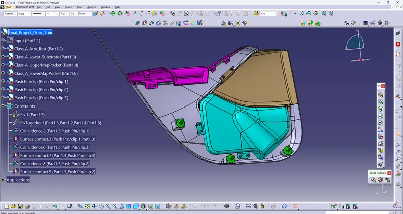
- Assembly of the push pins over the dog house in assembly workbench.
- Final submission.
Construction of Arm Rest
- From given class A surface of arm rest, analysing by boundary of the surface some where surafce are not form properly
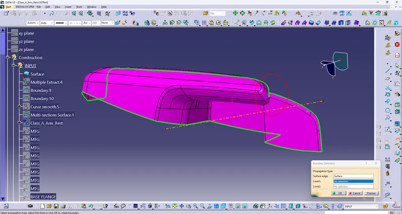
- on the surface has reconstruct and develop Class A surface
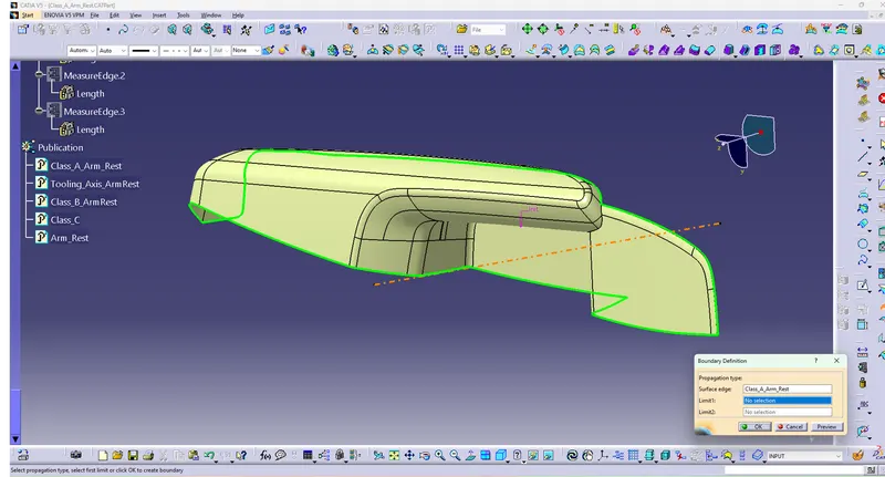
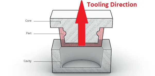
Tooling Axis:
Tooling Axis is the direction in which the Mold opens and closes. Part Drafts are generally given along this axis.
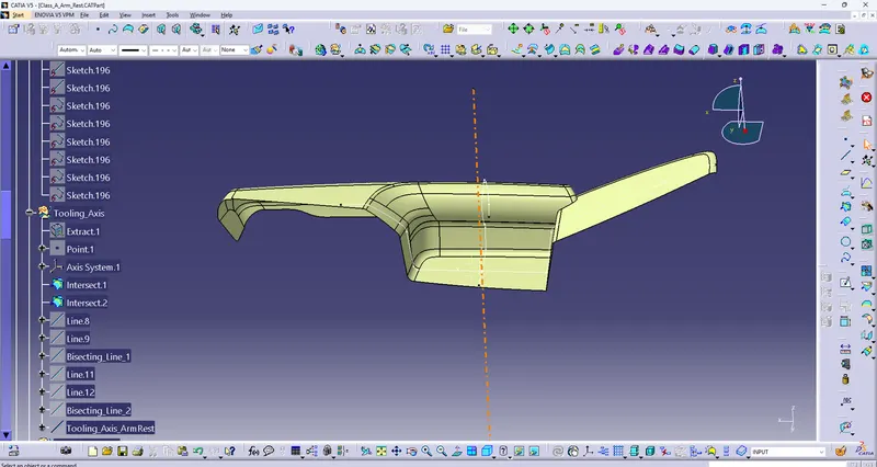
- Extract base surface from class A and Add point on the extract surface
- then add axis system on the point,intersection is created on XZ and YZ on the class a surface
- after end side of intersection line is construct along the intersection point and from the two ends of line .
- create Bisecting line, same as other intersection lines create bisecting line
- After from two bisecting lines, create line in between two bisecting line is Tooling axis line.
Class_B of Arm rest
- Offset the class A surface 2.5mm is measured from the given master section.
- Somewhere surface is broken, after construct on the surface by using sweep and multi section surface
- after trim those surfaces and completely formed Class_B surface.
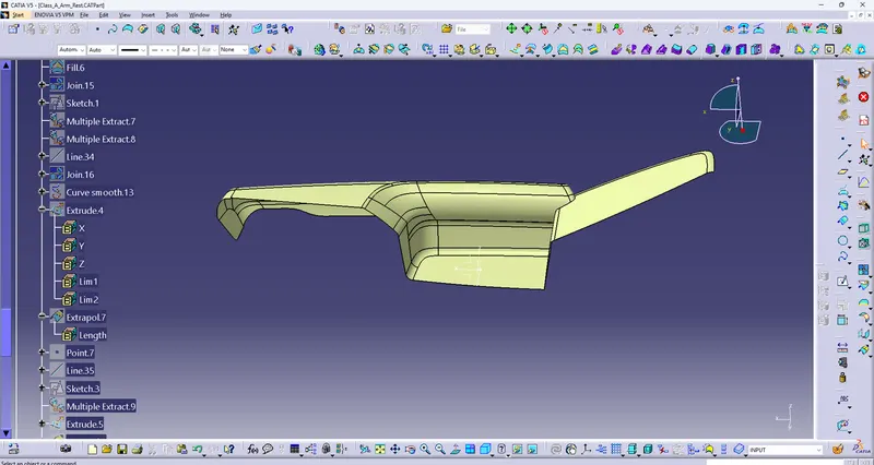
Class_C of Arm Rest
- Use sweep command to create a new surface an an angle with respect to a surface . This angle is dependant on draft angle for free edges and ususally 90 degree for mating surfaces .
- In areas where sweep is not possible , use Multi section surface to create a new surface .
- Join all surfaces to obtain C surface.
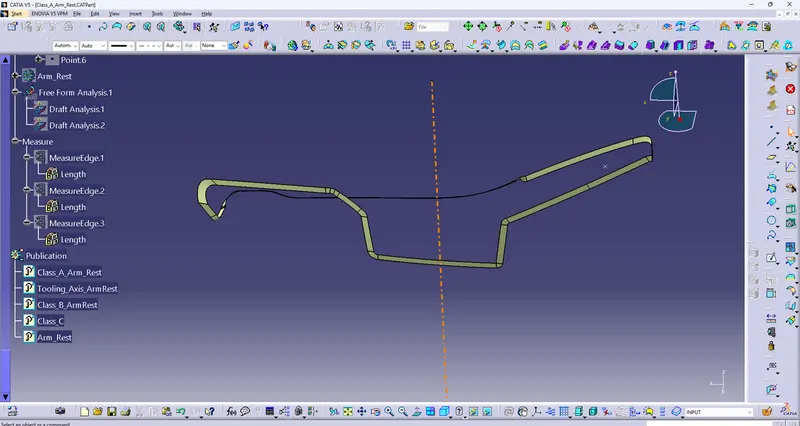
- Join Class A and Class C surface and trim Join surface and Class B surface.
- then closed boundary of surface is created, then closed surface in Part Design
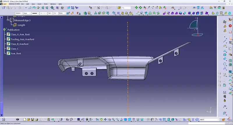
Heat Stakes mount and Ribs of Arm Rest
- After create heat stakes mount and ribs by master section
- By using of sweep and extrude create those master section of attachments
- then thicken those surface and assemble in main component by using Boolean Operation.
Construction Of Upper Map Pocket
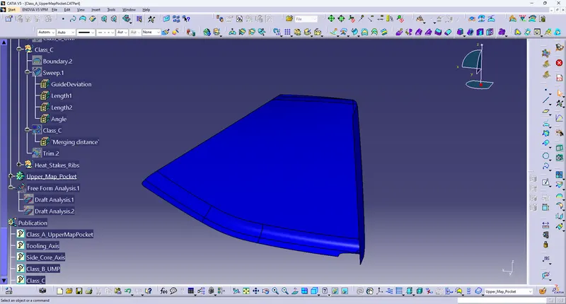
Class A surface of Upper Map Pocket (UMP)
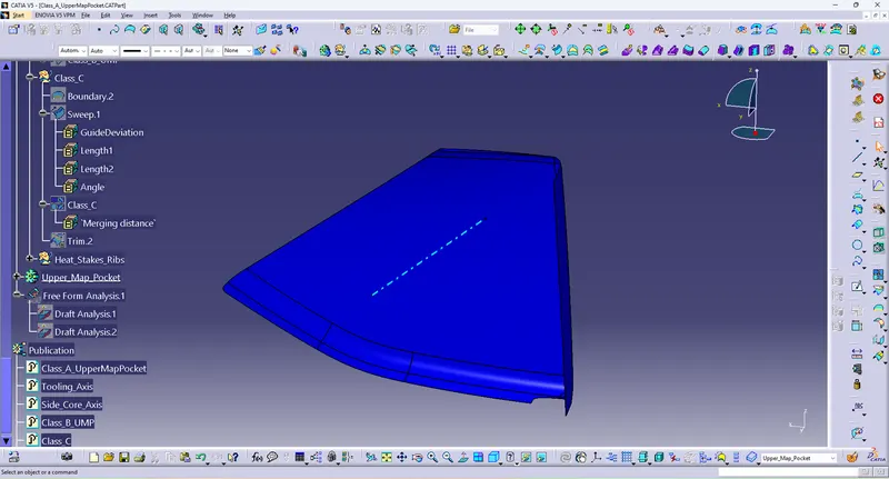
Tooling Axis
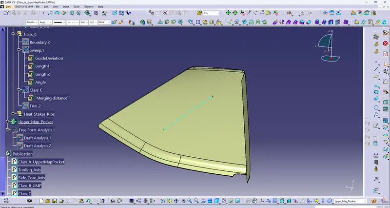
Class B surface of UMP
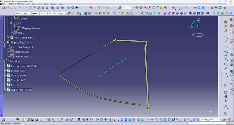
Class C surface of UMP
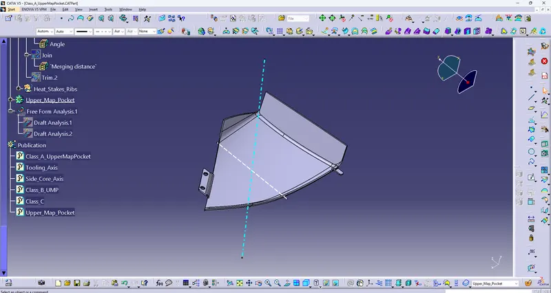
Side Core Axis
- Side core axis is created for attachment is design in main component
- its may not draft along in main tool axis.
- in Mould box, adding core or Sliding mechanism were provide to the special features may create on the component
- its may proportional to the main tool axis. so, we assign those features along another tooling axis is called side core axis
- where draft angle is created to the attachment features along Pulling Direction of side core axis.
Construction of Lower Map Pocket(LMP)
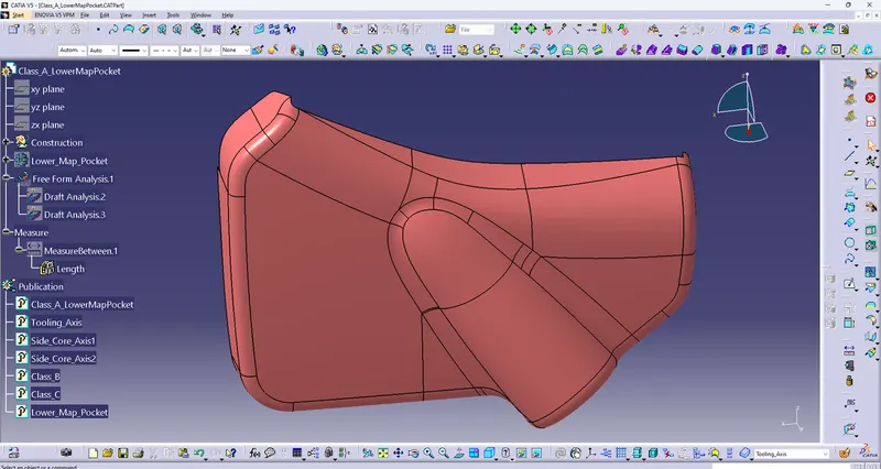
Class A surface of Lower Map Pocket (LMP)
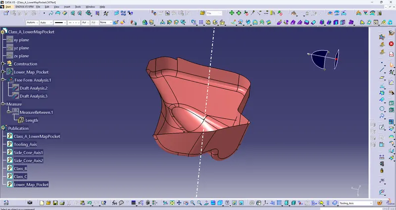
Tooling Axis
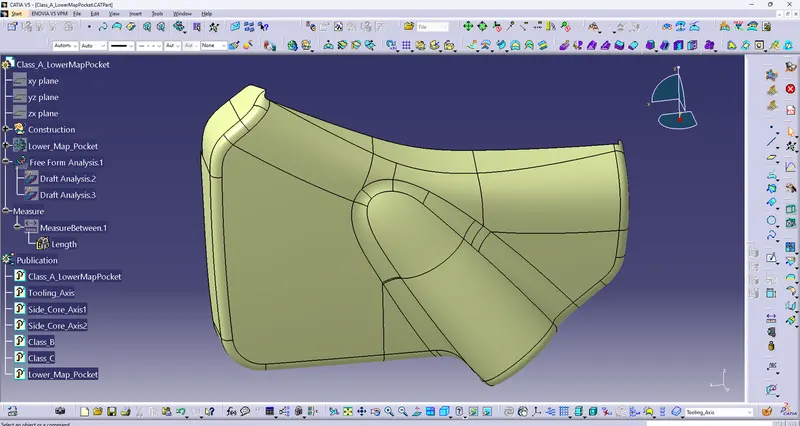
Class B surface of LMP
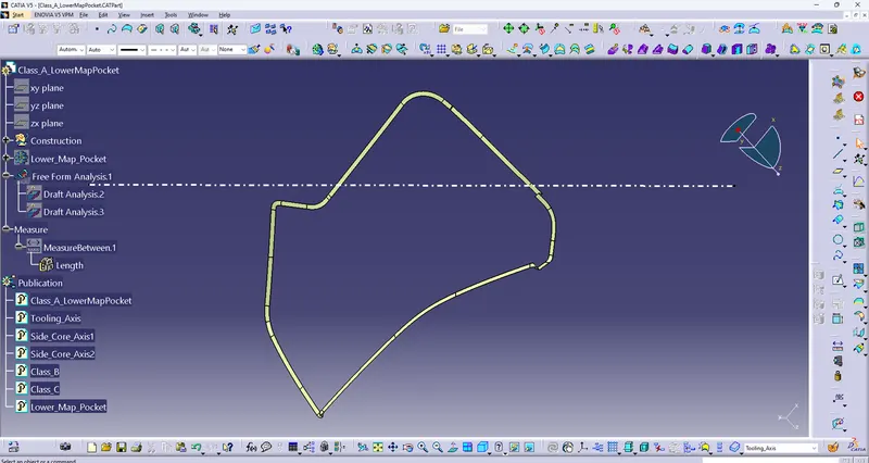
Class C surface of LMP
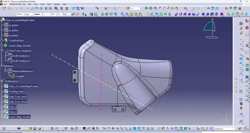
Solid component of LMP with attachments
Construction Of Lower Substrate
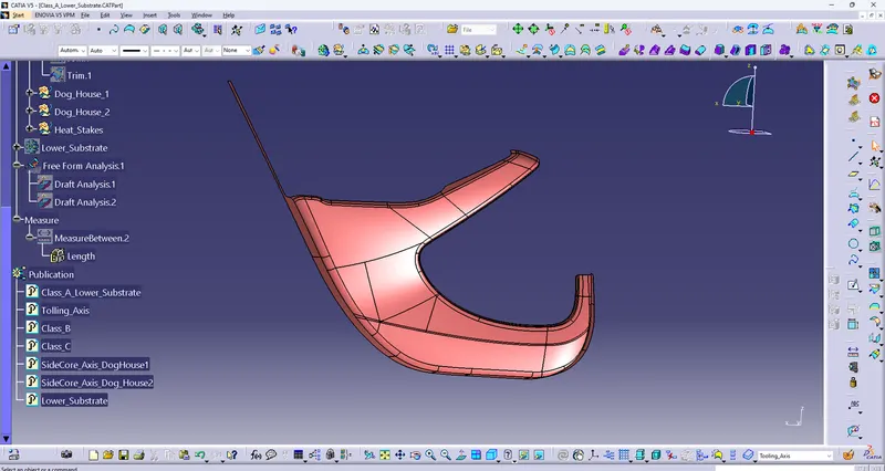
Class A surface of Lower substrate
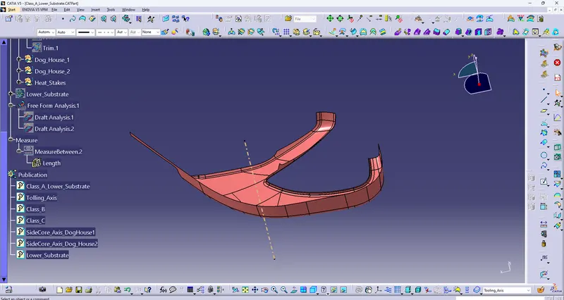
Tooling Axis
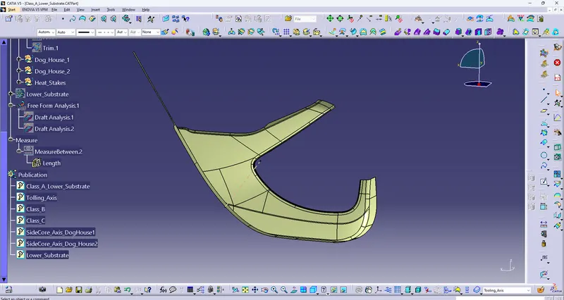
Class B surface of Lower substrate
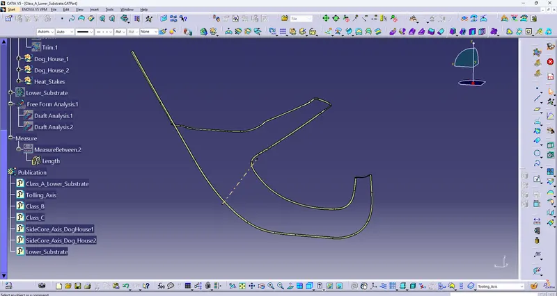
Class C surface of Lower substrate
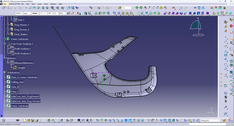
Solid Copmponent of Lower subtrate with heat stakes, Dog House attachments
Draft Analysis of Door Trim Components
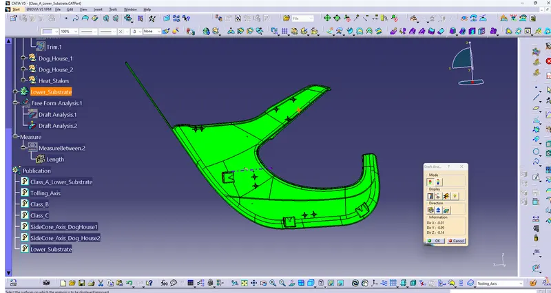
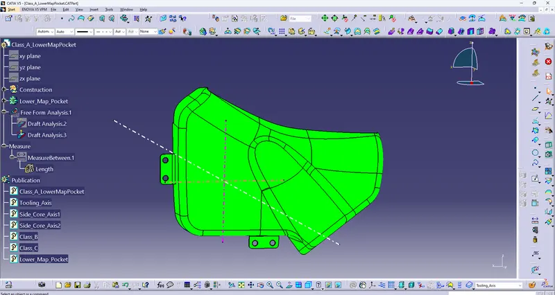
Assembly Workbench of Door Trim Components
Conclusion
In the Final Project of Door Trim, Challenging is creation of attachments features for the components and final output of design is made as per requirements of engineering standard and design standard.