Week 11 - Final project
FINAL PROJECT : DEVELOPMENT OF DOOR TRIM PANEL
AIM :
To develop the front door trim panel of a car with the class A surface which is received from a class A team then convert it into a part body with a minimum 3 degree draft and also develop attachment features like heat stakes, dog house, stiffners etc, using OEM design standards to fix the automotive parts together where ever it is required and get the model to be read for analysis team and also for the final production.
PROCEDURE :
The given igs file type model should be first attached and form them into class A surfaces where the model includes patches of bottle holder, map pocket, Lower substrate, Door arm rest and upper substrate.
The Igs model is given below :
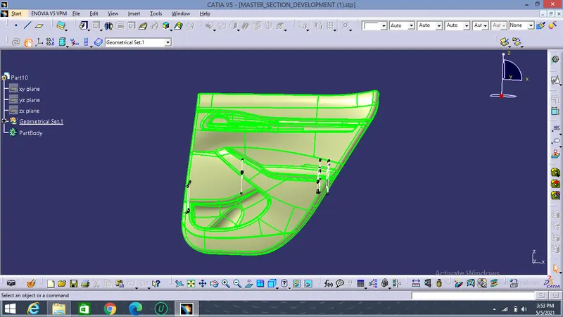
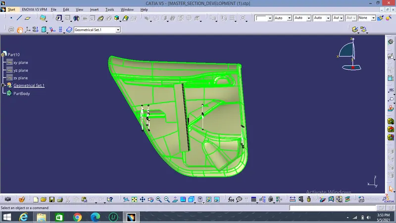
So now all the patched input should be attached together to form seperate parts using join option or join by no propagation.
Basically there are 6subparts in it as Bottle holder, Map pocket, Lower substrate, Upper substarte, Door arm rest and handle.
Now here we are going to work on the Bottle holder, Map pocket, door arm rest and the lower substrate.
So first we are going to create the class A surfaces from the given input then work on them to create class C and closed bodies, there after we proceed with the B-side features.
1. BOTTLE HOLDER :
The class A of the bottle holder will be looking like as in below image after seperating from the patches.
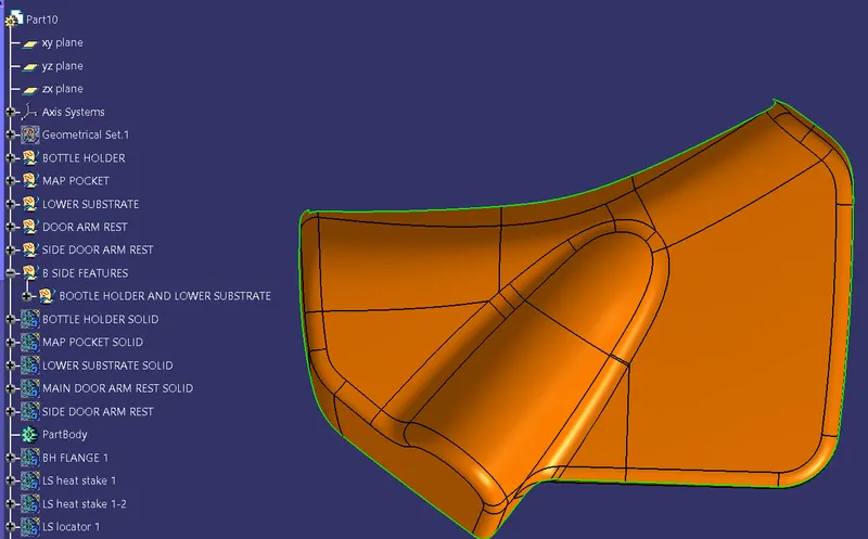
After getting the class A surface the first thing that should be performed is tooling axis and draft analysis for the class A surface.
DRAFT ANALYSIS :
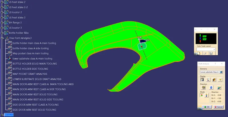
If you're designing a product that will be manufactured using injection molding, use the Draft Analysis tool to analyze the draft angle. This allows you to verify whether the product will be easily removed from the mold, or if you will need to correct the draft to facilitate mold release.
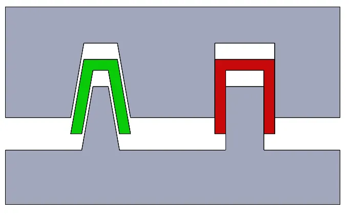
What is a draft angle? When designing a product to be injection molded, the sides of the object should not be parallel to the pull direction (the direction in which the mold is pulled away from the object). Rather, any parallel sides need to be angled slightly so that the mold can be pulled away from the object easily, without deformation or damage. This slight angle is called draft. The deeper the mold, the more draft needed.
To analyze the draft of a design:
Click the Draft Analysis icon or choose the Tools > Analyze > Draft Analysis menu command.
The analysis is run automatically.
It is assumed that the mold will be pulled along the Z axis. You can change the Pull Direction in the Control Panel, or click and drag the Direction and Origin handles in the modeling views.
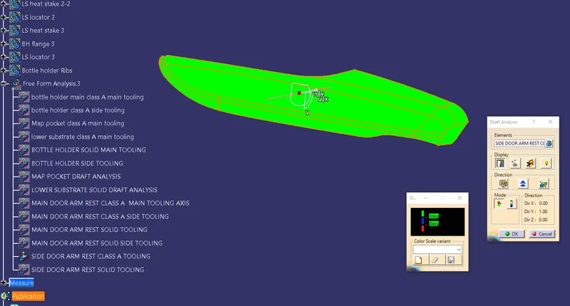
By default, an angle of 3° is considered sufficient draft. To use a different tolerance value, modify the Draft Angle in the Control Panel.
By default, an angle of 0° is considered insufficient draft. To use a different tolerance value, modify the Warning Angle in the Control Panel.
Green indicates a region where sufficient draft has been detected, in the same direction as the current pull direction. You can change the legend color using the Positive Draft parameter in the Control Panel.
Blue indicates a region where insufficient draft has been detected; you'll need to correct the draft of this region. You can change the legend color using the Requires Draft parameter in the Control Panel.
Red indicates a region where sufficient draft has been detected, in the opposite direction of the current pull direction. You can change the legend color using the Negative Draft parameter in the Control Panel.
Pull Direction :
Use to define the pull direction.
X Axis: If the object is aligned with the world coordinate system, the mold will be pulled away from the right side of the object.
Y Axis: If the object is aligned with the world coordinate system, the mold will be pulled away from the back side of the object.
Z Axis: This is the default. If the object is aligned with the world coordinate system, the mold will be pulled away from the top side of the object.
Custom: Allows you to define an alternative pull direction by clicking and dragging the Direction and Origin handles in the modeling views.
The above compass sign is used to arrange the compass in the draft direction.
Invert Direction: Use to invert the pull direction. For example, if the object is aligned with the world coordinate system, select Z Axis and Invert Direction to indicate that the mold will be pulled away from the bottom side of the object.
Use to change the legend colors and define the tolerance values for sufficient and insufficient draft.
Positive Draft: Refers to a region where sufficient draft has been detected, in the same direction as the current pull direction. By default, these regions appear green, but you can change the legend color using the color palette.
Draft Angle (°): Use to define the tolerance value for sufficient draft. The default value is 1°. Select a value that is greater than or equal to 0°; it must also be greater than or equal to the Warning Angle.
Requires Draft: Refers to a region where insufficient draft has been detected. By default, these regions appear yellow, but you can change the color using the color palette.
Warning Angle (°): Use to define the tolerance value for insufficient draft. The default value is 0°. It must be less than or equal to the Draft Angle.
Negative Draft: Refers to a region where sufficient draft has been detected, in the direction opposite to the current pull direction. By default, these regions appear red, but you can change the color using the color palette.
Below is the image of performed draft analysis for the surface :
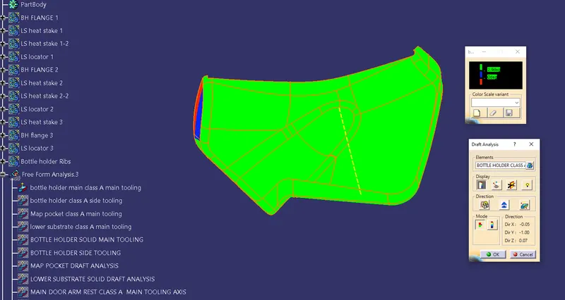
As there is a an issue with the clearing of the side tooling axis we provide a slider axis for clearing the side surface.
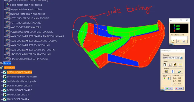
After performing the side core axis that surface part is cleared with the draft angle with 2.9 degree.
After successful clearing of draft analysis we need to build up a class C surface to get a closed body for the bottle holder.
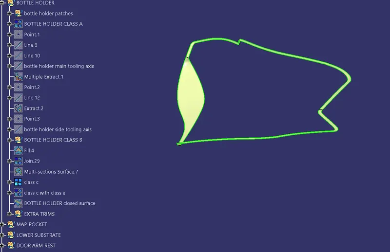
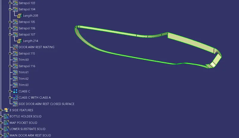
Now class C is a surface which is created from the class A edges with a draft angle of 3 degree for extracting the part safely without any ruptured surface.
The class C surface for the bottle holder is given below :
Below is the image of class C attached to class A surface that to be trimmed with class B surface.
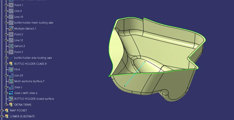
Now we need to offset the class A surface to get the class B surface with the given thickness of 2.5mm.
The trimmed and final closed body for the bottle holder for creation of solid plastic part is given below :
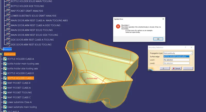
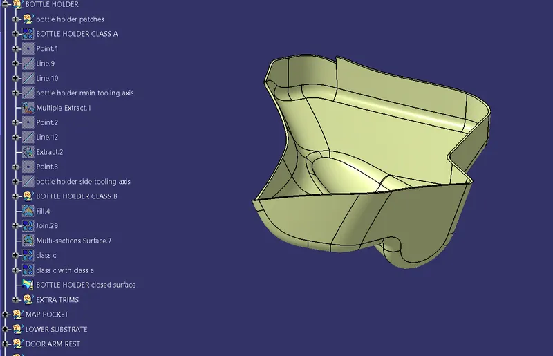
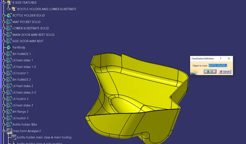
Now again we need to perform the draft analysis for the part body with a material mode :
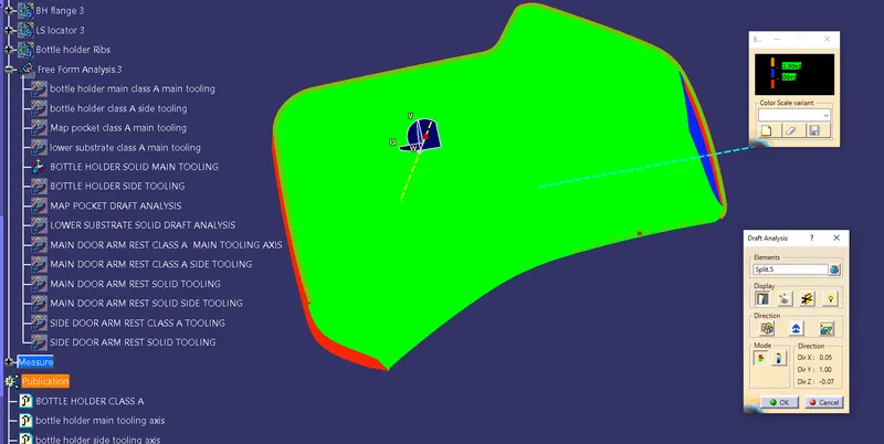
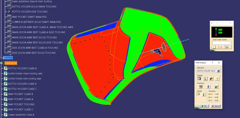
So by this we can say that draft analysis for the bottle holder plastic part is done with a 3 degree draft.
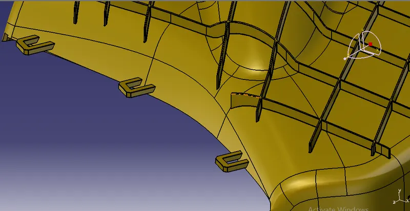
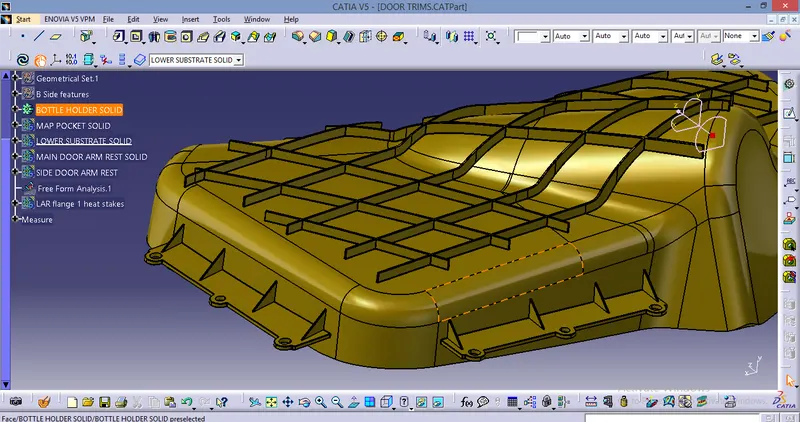
B-Side Features :
The basic b-side features that were mainly used in the mould design for plastics are :
- Screw-bose
- heat stakes
- Flanges
- Ribs
- Stiffners
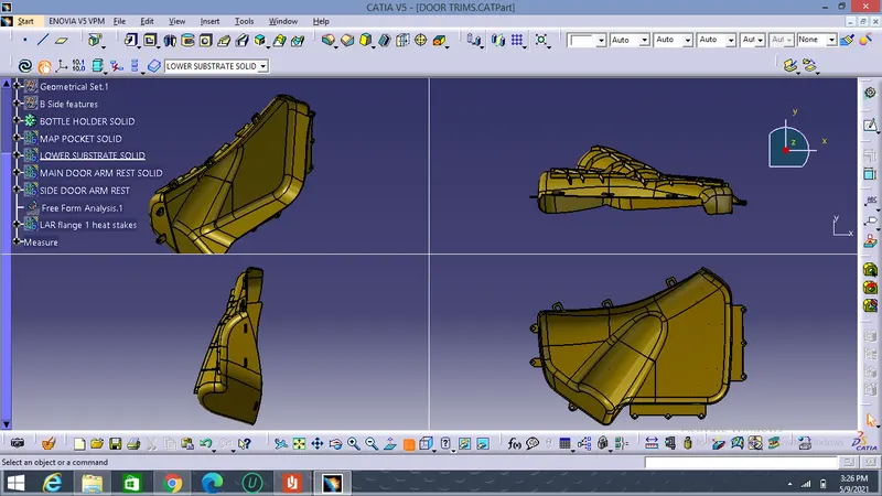
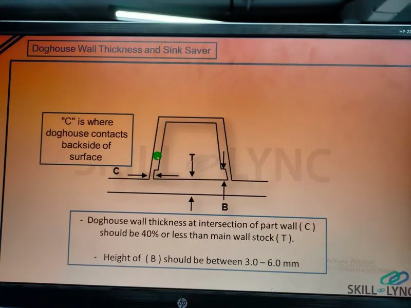
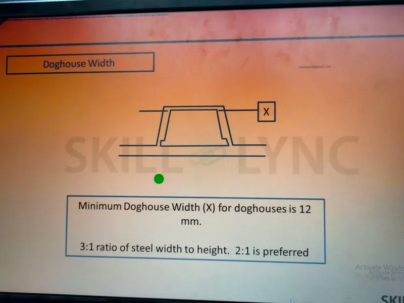
- Dog house
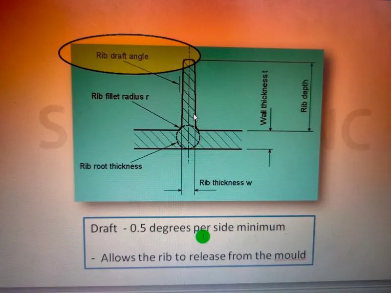
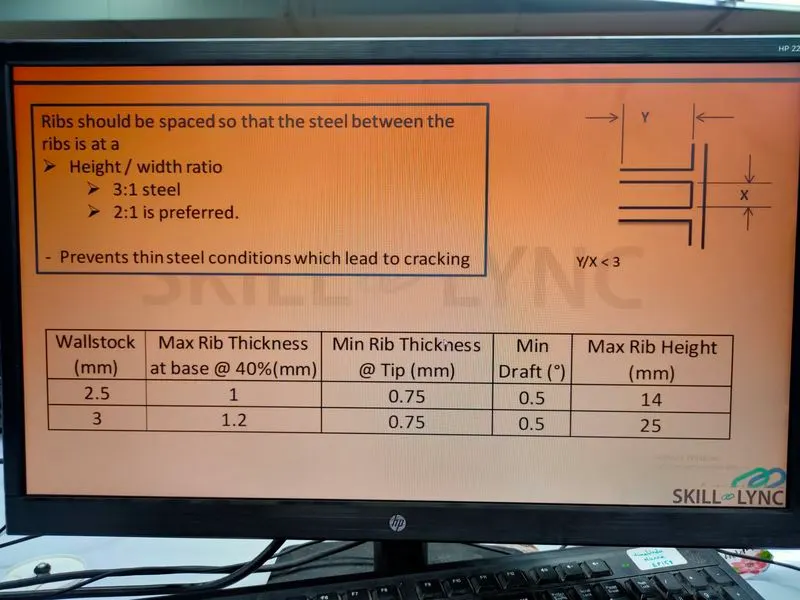
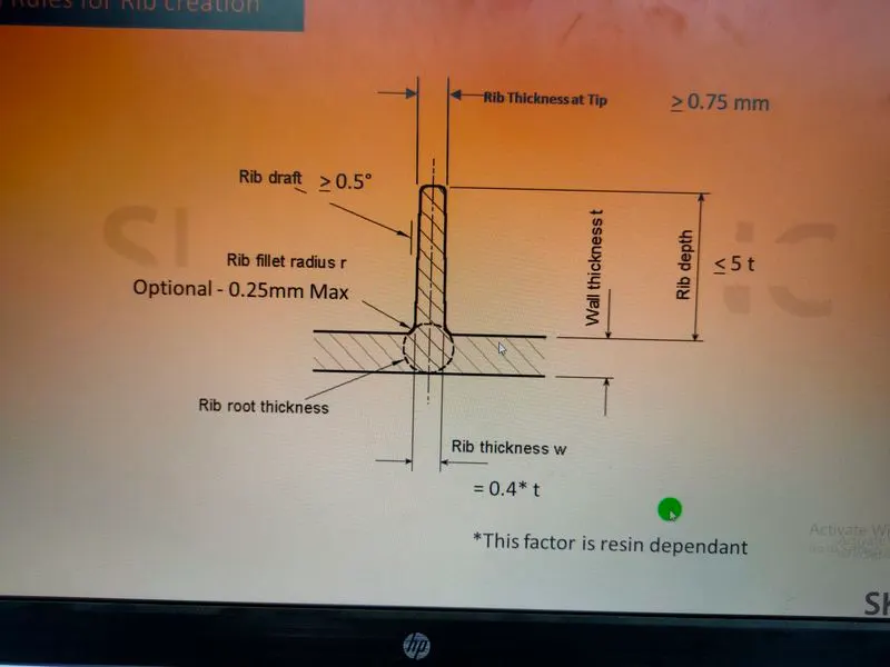
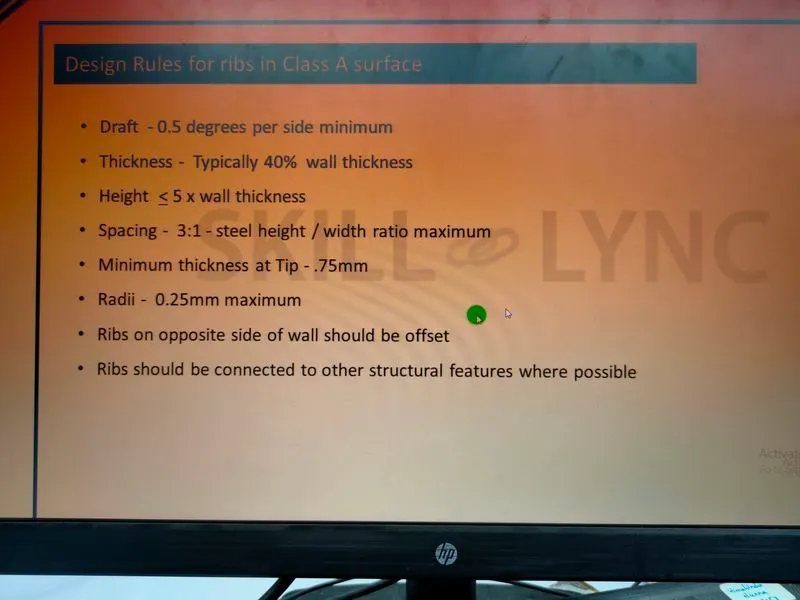
And according to these features there are some OEM standard design rules that must be followed while designing these features.
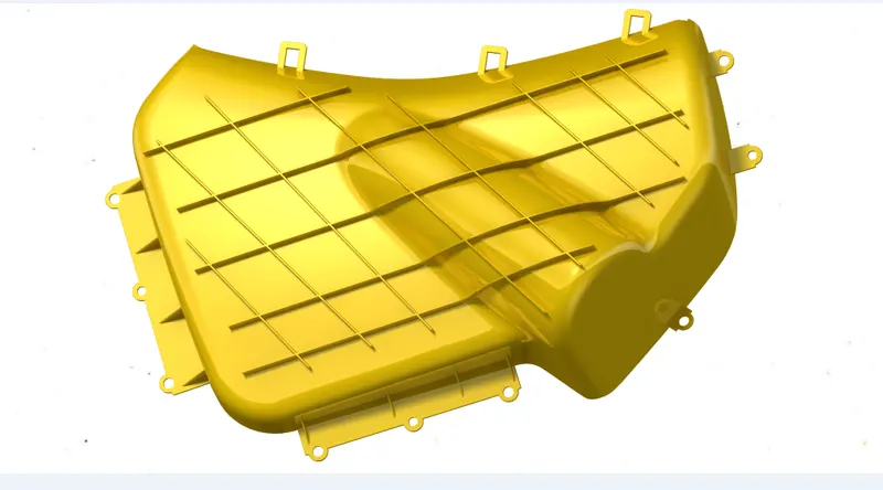
Rib Design :
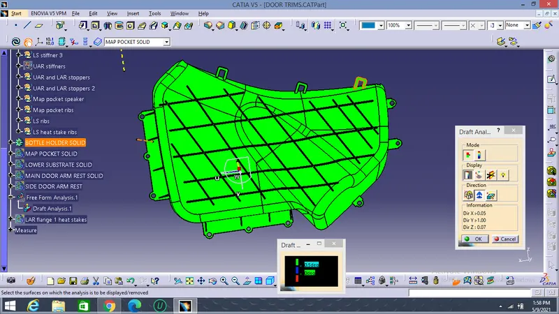
The draft analsis for the bottle holder with b-side features is shown below :
The final rendered image of the bottle holder :
Dog house design :
MAP POCKET :
The class A of the Map pocket will be looking like as in below image after seperating from the patches.
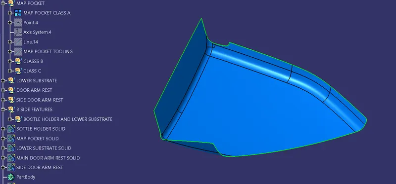
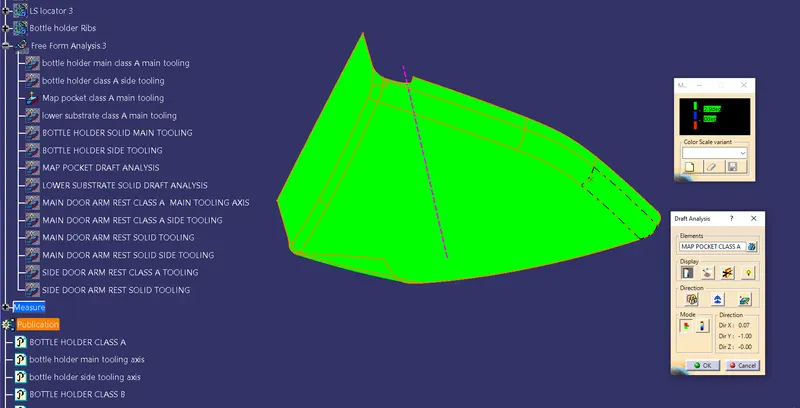
Below is the image of performed draft analysis for the surface :
After successful clearing of draft analysis we need to build up a class C surface to get a closed body for the Map pocket.
Now class C is a surface which is created from the class A edges with a draft angle of 3 degree for extracting the part safely without any ruptured surface.
The class C surface for the Map pocket is given below :
Below is the image of class C attached to class A surface that to be trimmed with class B surface.
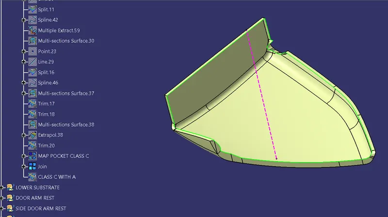
Now we need to offset the class A surface to get the class B surface with the given thickness of 2.5mm.
The trimmed and final closed body for the map pocket for creation of solid plastic part is given below :
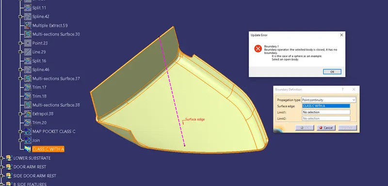
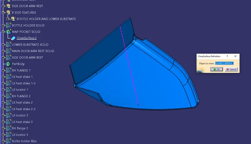
Now again we need to perform the draft analysis for the part body with a material mode :
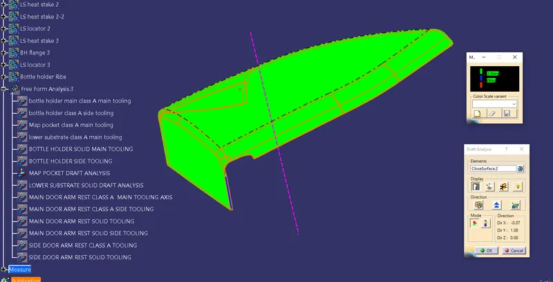
B-side features for Map pocket :
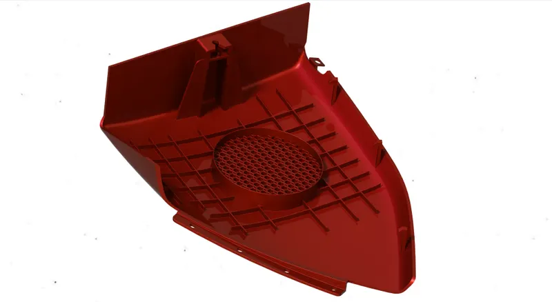
Speaker design and ribs for map pocket stiffness :
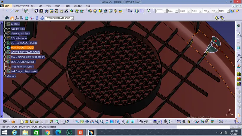
Flanges and Bottle holder holding snap fits :
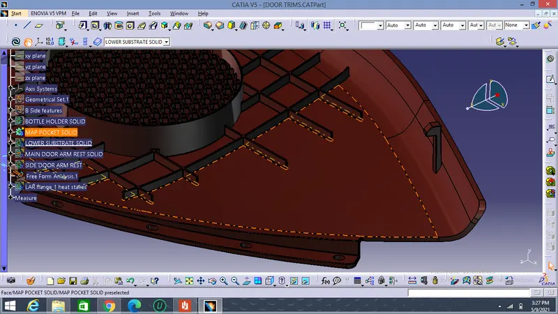
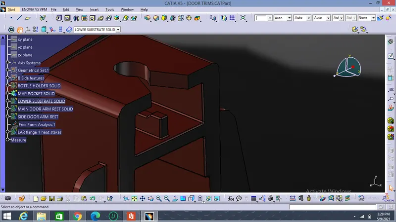
Dog house for overall stiffness and for attachment of other attachment features using retainer clips :
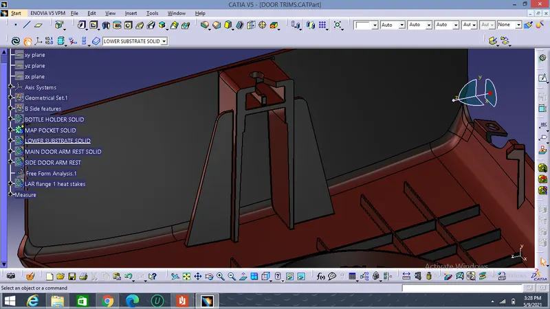
Gib headed stopper for stopping the motion of the retainer clips :
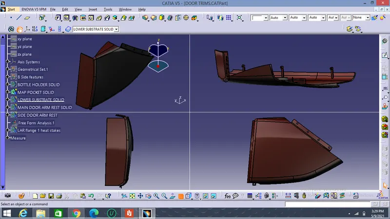
All views of Map pocket is given below :
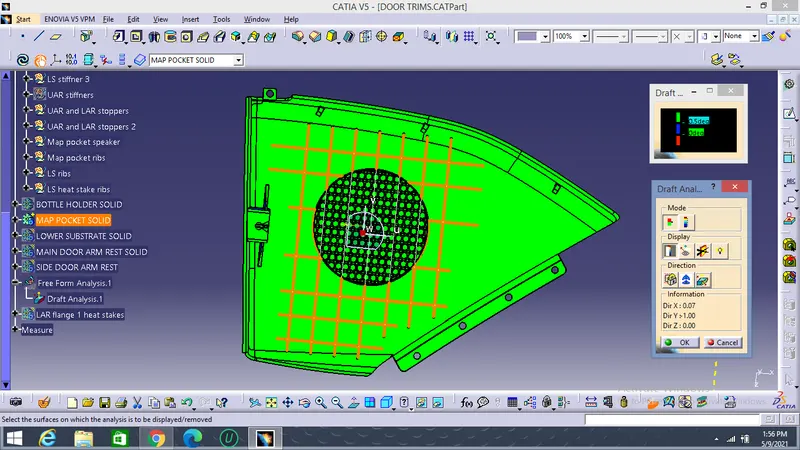
The draft analsis for the Map pocket with b-side features is shown below :
Final view of the Map pocket with B-side features with rendering:
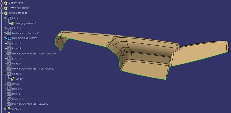
DOOR ARM REST :
The total class A surface of door arm rest image is given below :
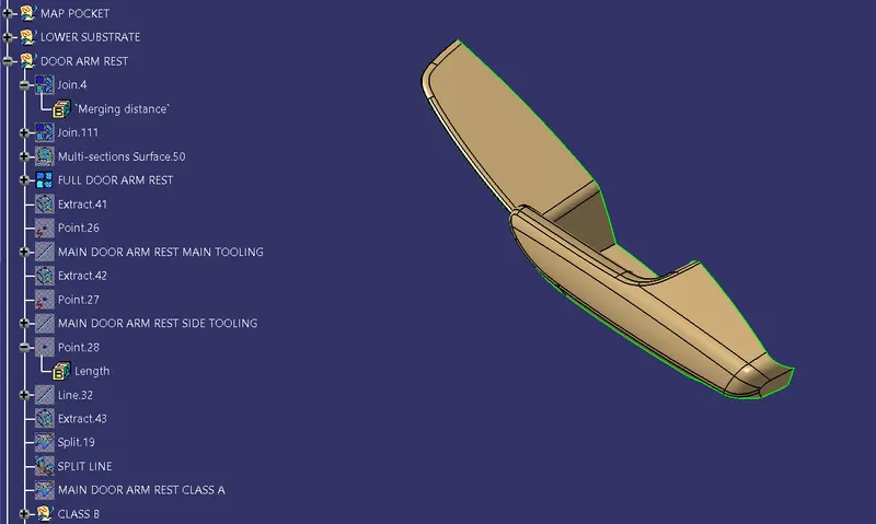
The draft analysis for the total class A :
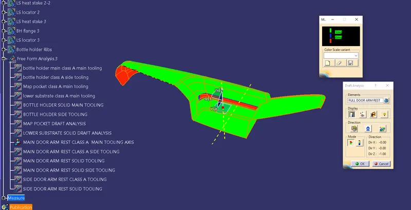
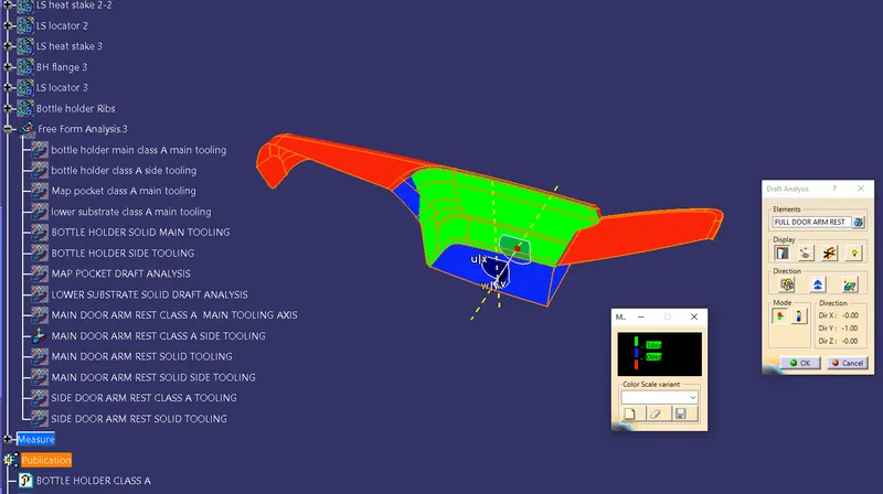
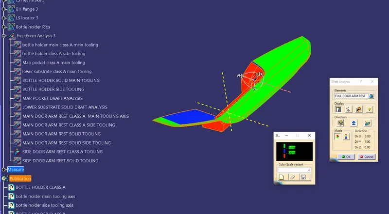
To perform further operations on the door arm rest there is a need to split the door arm rest into two parts as the surface feature of it little curved and the ejection of the part from the mould is bit difficult.
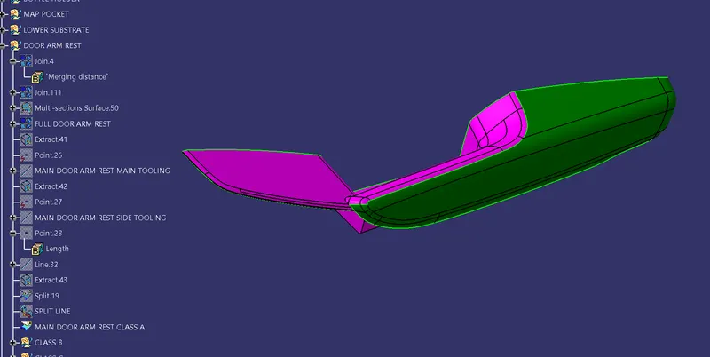
Here from the above image we call pink surface as upper arm rest and the green is lower arm rest
UPPER ARM REST :
Class A surface for the Upper arm rest is given below :
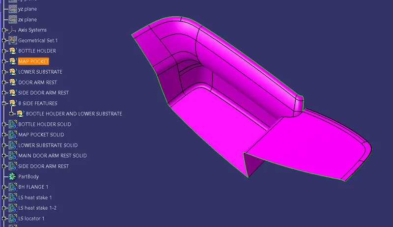
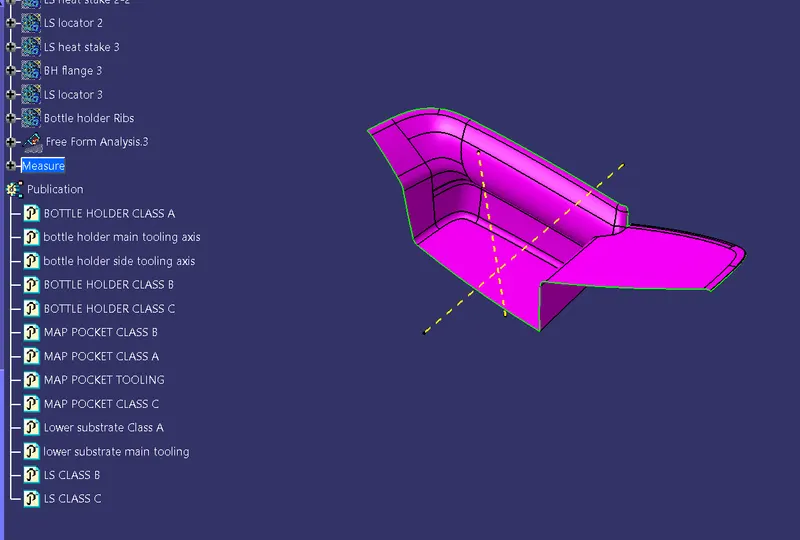
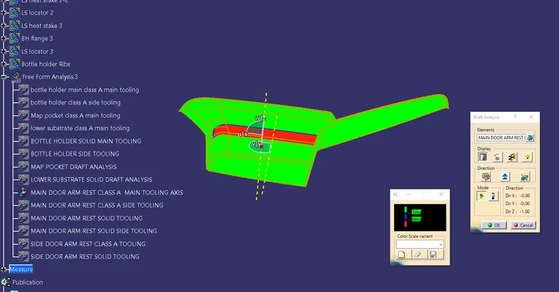
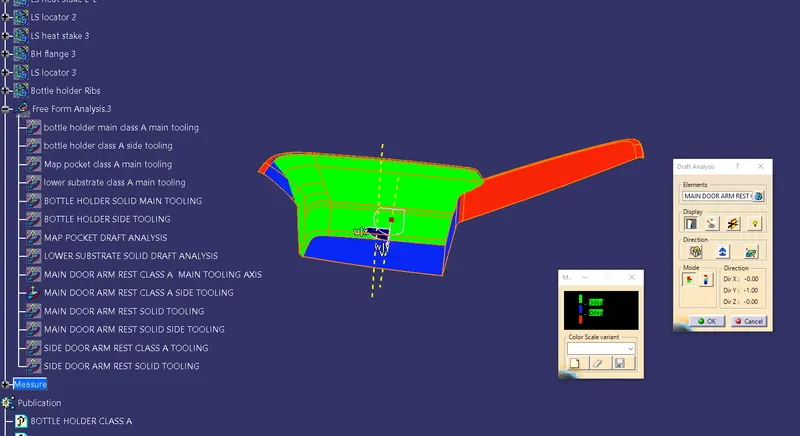
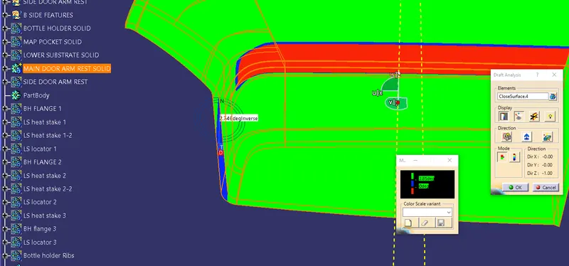
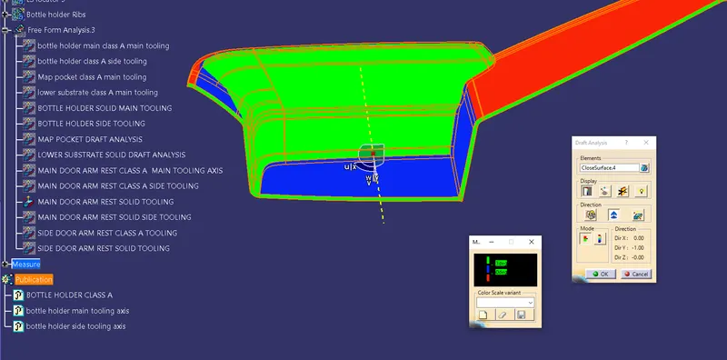
The draft analysis performed on Upper arm rest has two dividions one is from main tooling axis and the other is Side tooling axis.
The main and side tooling draft analysis for upper arm rest is given below :
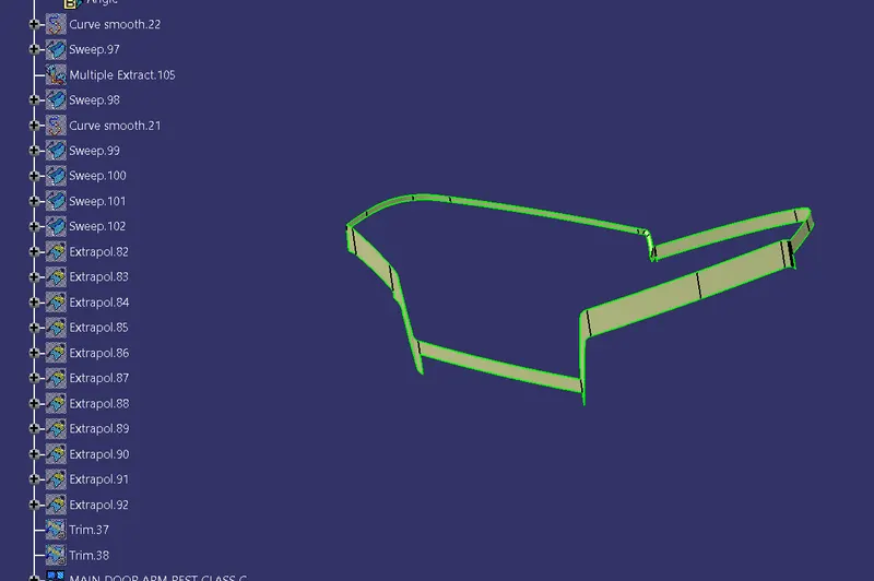
The class C for the upper arm rest created with 3 degree draft is shown below using class A surface :
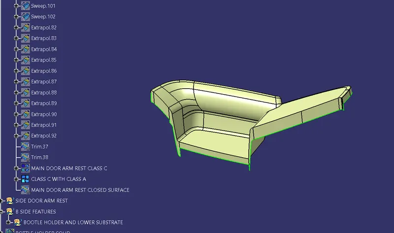
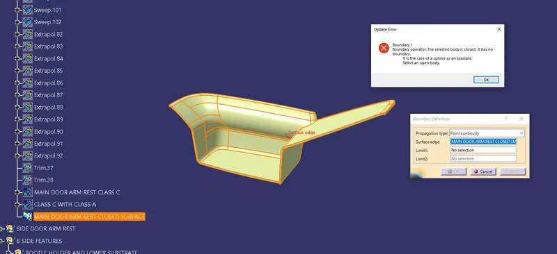
The closed body for the upper arm rest is shown in the below image which is used to create solid plastic part :
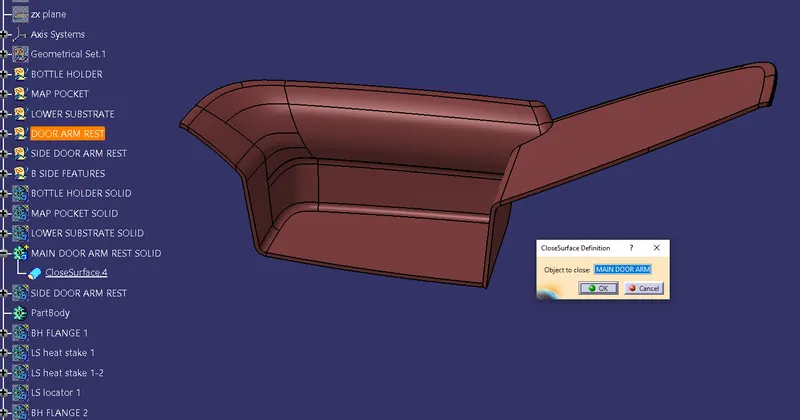
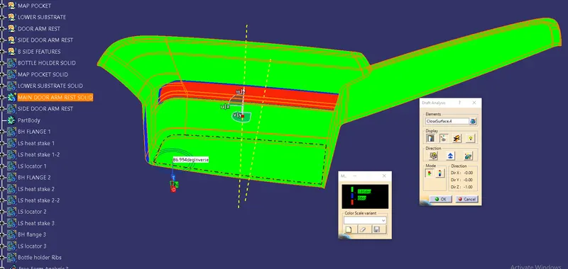
The draft analysis for the solid part is shown below :
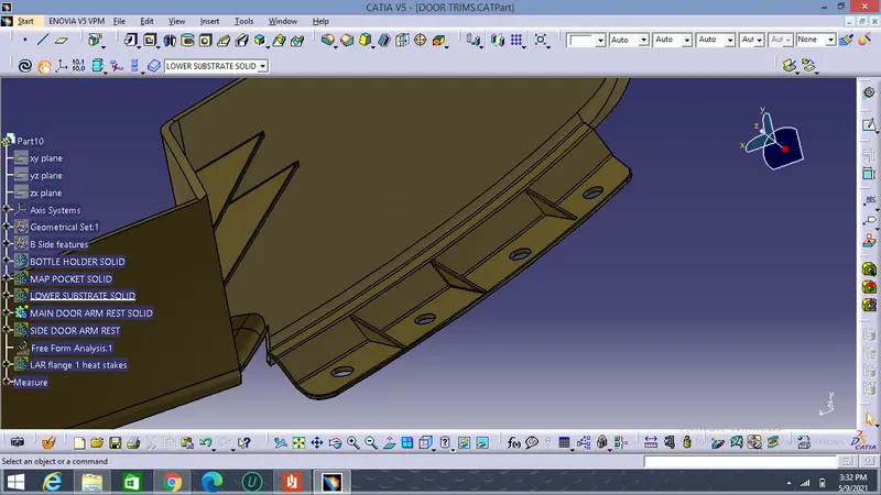
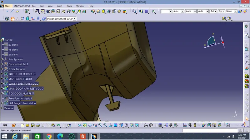
B-Side features for the upper arm rest :
Flanges, stopper for lower arm rest and the ribs for upper arm rest is shown in the below image :
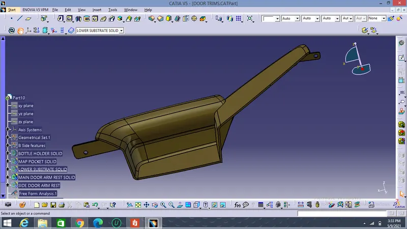
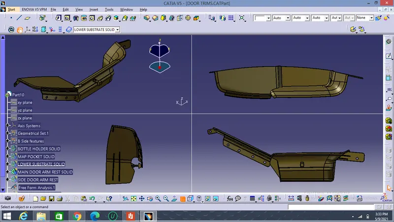
All views of upper arm rest is shown in the below image :
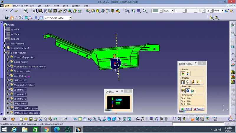
The draft analsis for the upper arm rest with b-side features is shown below :
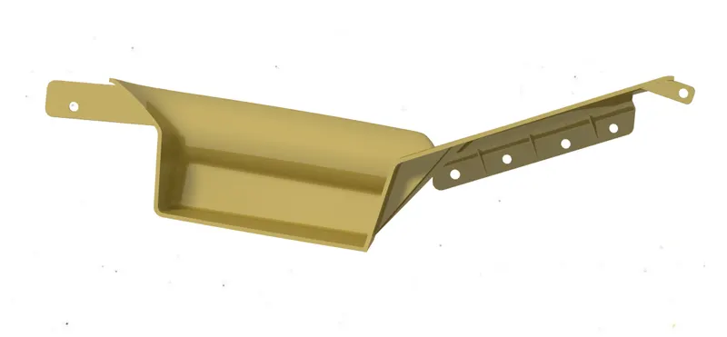
Final render image of upper arm rest :
LOWER ARM REST :
The class A for lower arm rest is given below in the image :
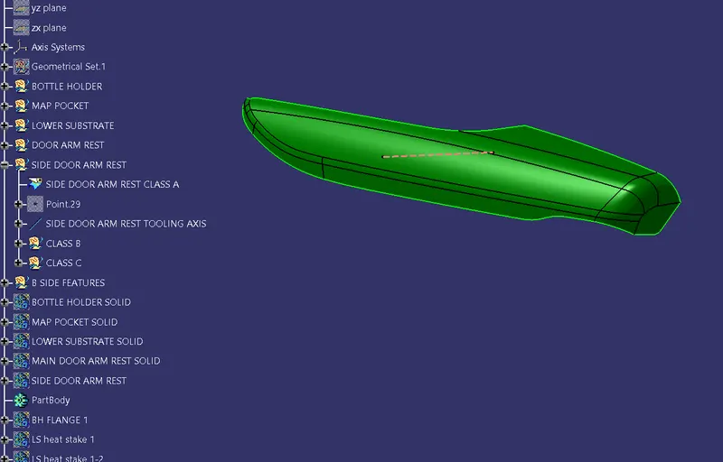
The draft analysis for the lower arm rest with a minimum draft angle of 3 degree :
The class C surface which is developed from the class A surface with draft direction of 3 degree is given below :
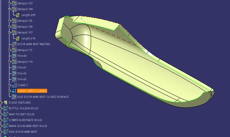
Class A with class C is given in the below image :
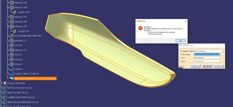
The draft analysis for the final part body is done with a minimum 3 degree draft angle :
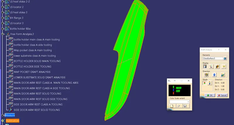
B-Side features for Lower arm rest :
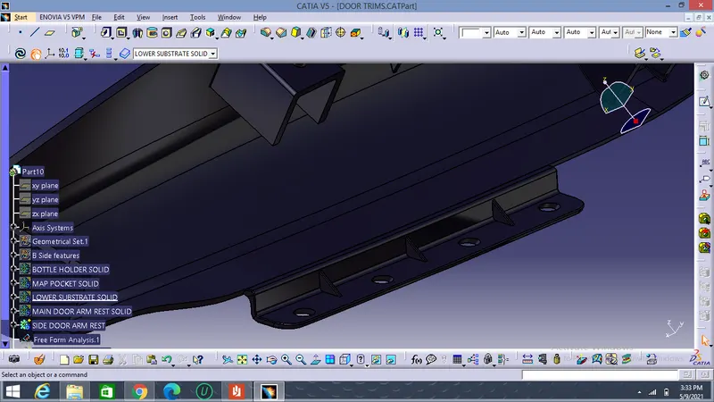
The flanges for attaching lower arm rest to the lower substrate is given below :
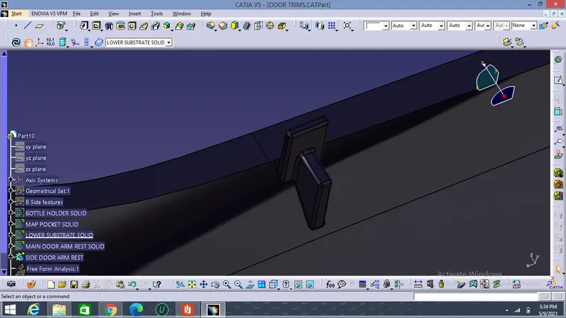
The stoppers that stops the motion of the upper arm rest inside these are used which are shown below in the image :
The all views of lower arm rest is shown in the below image :
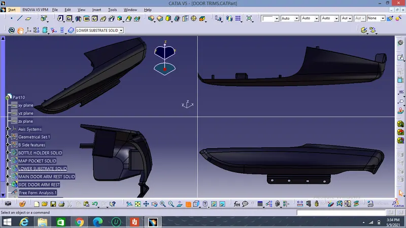
The draft analsis for the lower arm rest with b-side features is shown below :
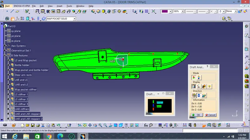
The final rendered image of lower arm rest is given below :
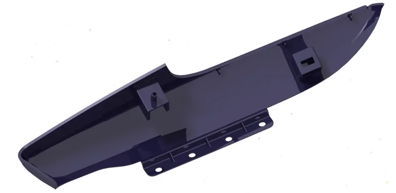
LOWER SUBSTRATE :
The class A for the lower substrate is given below :
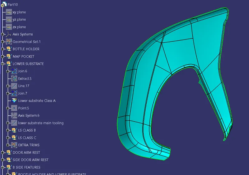
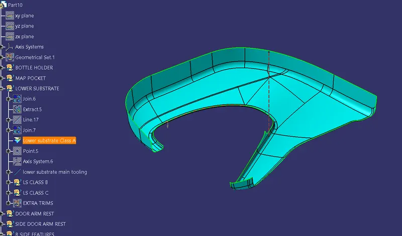
The draft analysis for the lower substrate class A surface is given below :
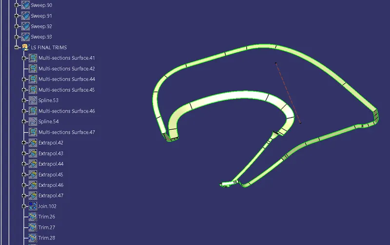
Class C surface for the lower substrate is given below which is created with the draft direction using draft tool using class A surafce :
Class C attached with class A surface is given below :
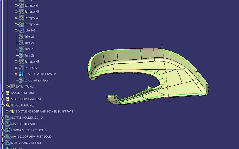
The closed surface for the lower substrate is given in the below image :
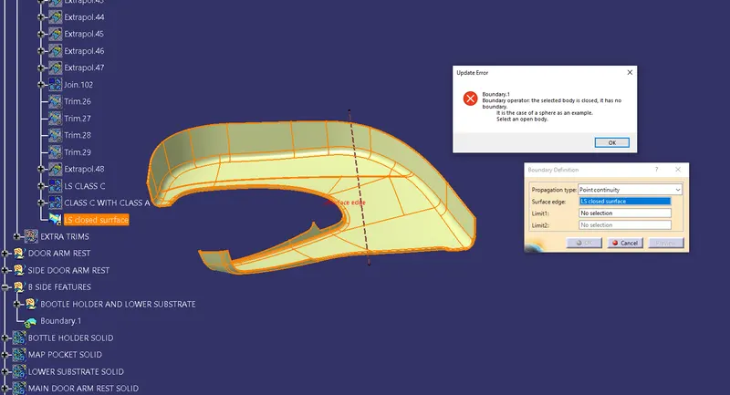
The Draft analysis for the lower substrate solid part is given below :
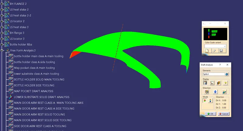
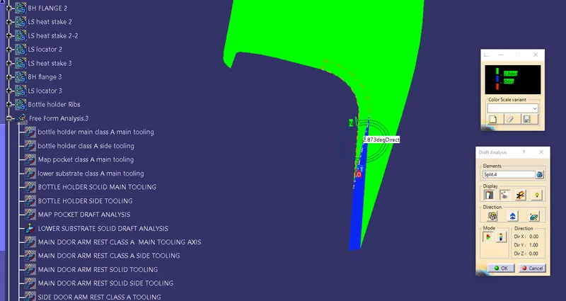
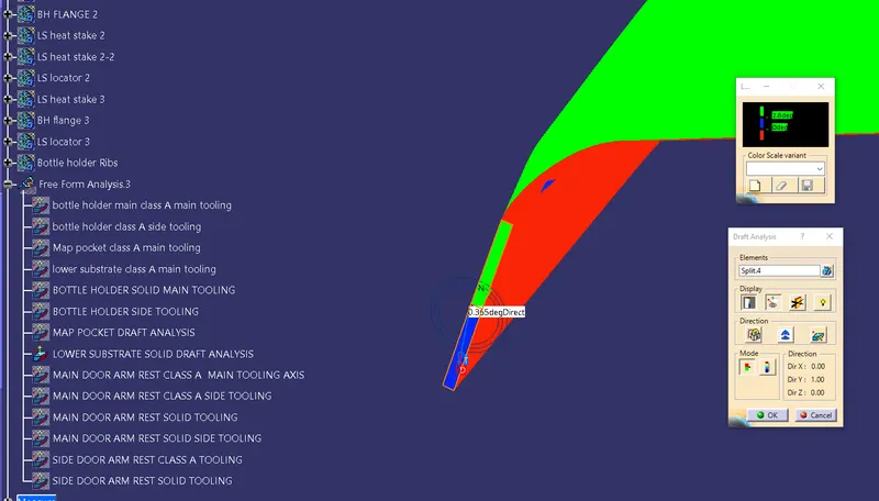
Lower Substrate B-side features :
Dog house and ribs based on standard design rules for lower substrate is given below in the image :
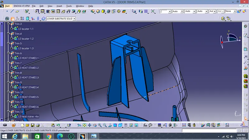
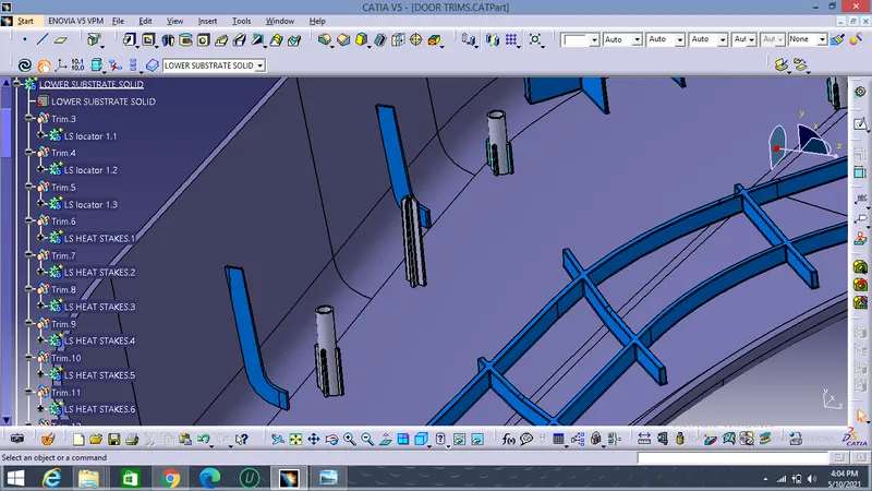
Locators, heat stakes and ribs for stiffness of the component is given below :
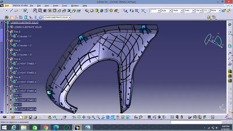
Draft analysis for the lower substrate final part body :
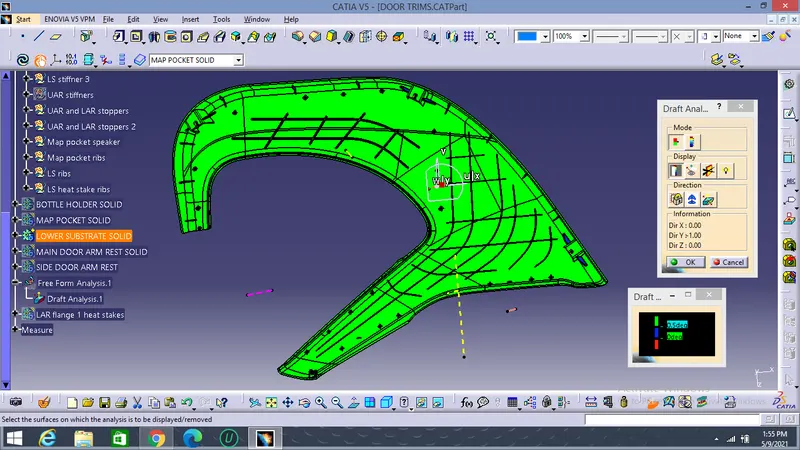
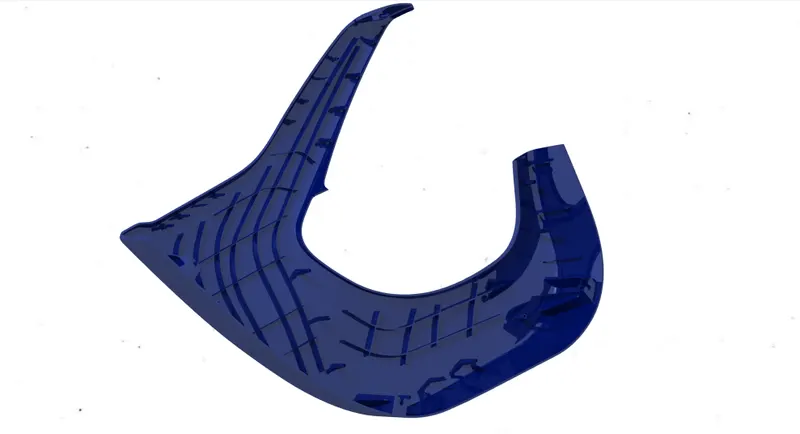
Final rendered image of the lower substrate :
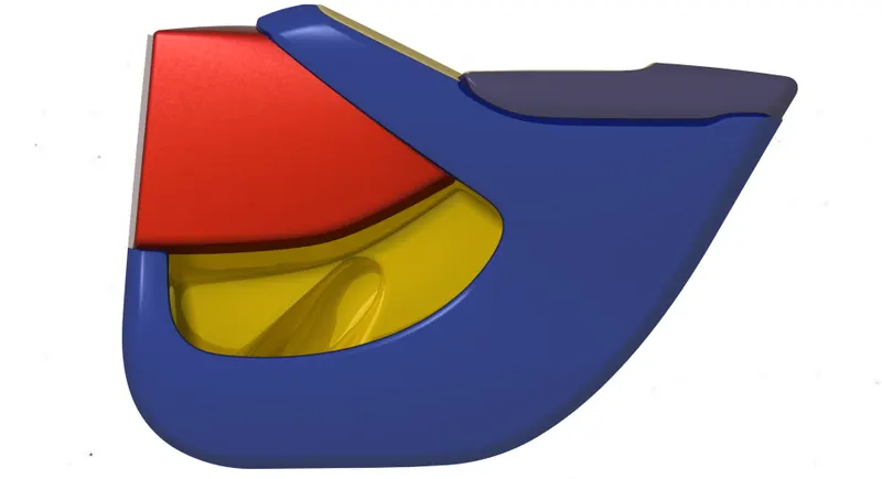
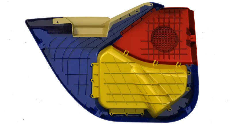
Final images for total Door panel trims is shown below :
GOOGLE DRIVE LINK FOR DOOR PANEL TRIMS :