Week 11 - Final project
SCREENSHOTS:
1. ARM REST:
In this armrest class a surface we will find some imperfections. so first of all, we need to check whether the imperfection is resolved by using the join command or not. If the imperfection appears again we will do some modifications where the imperfection occurs and we will consider the modified class a as our class a for future whole processes.
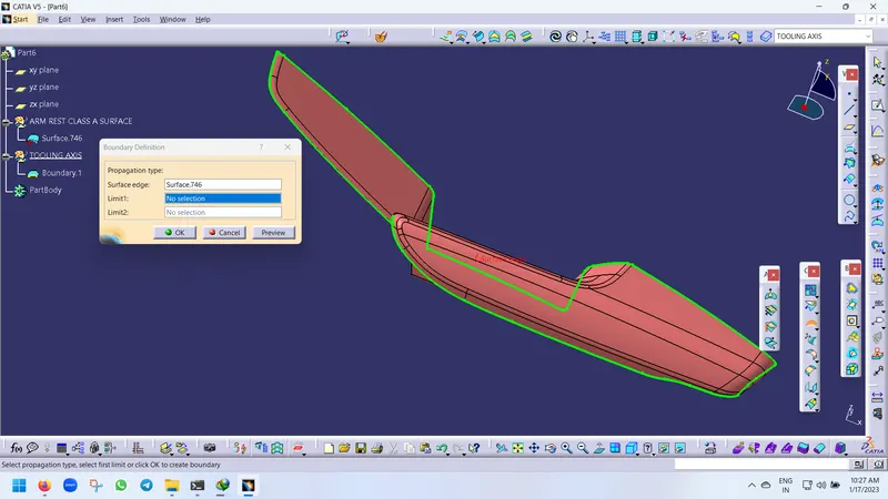
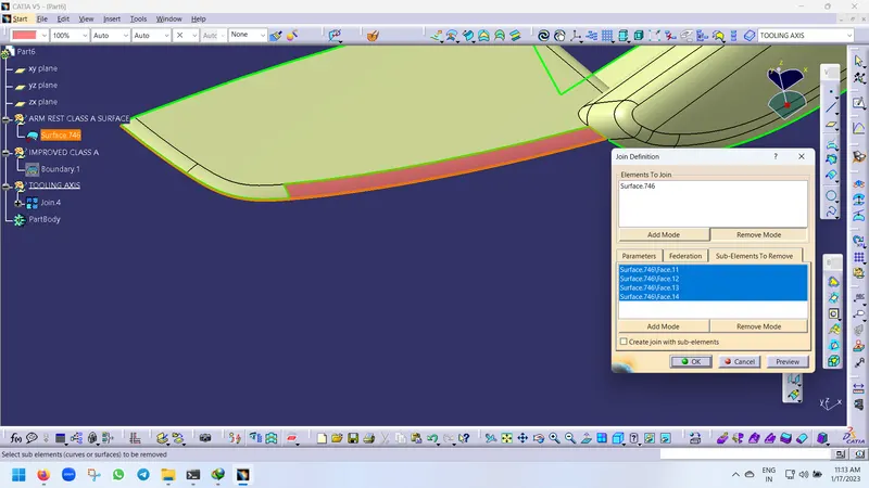
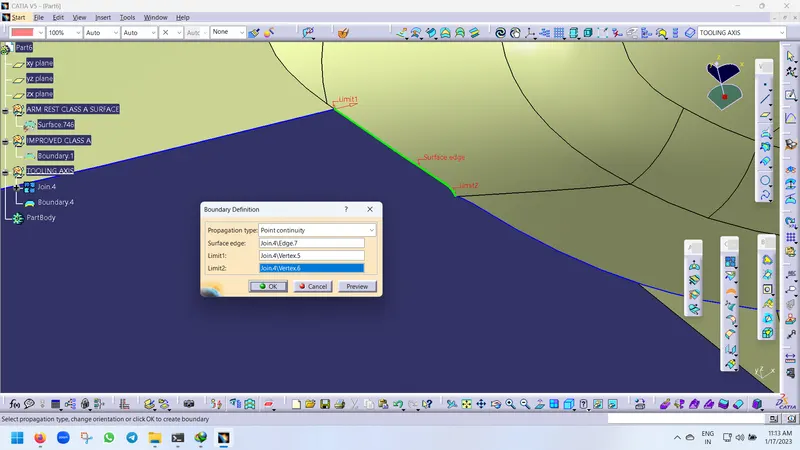
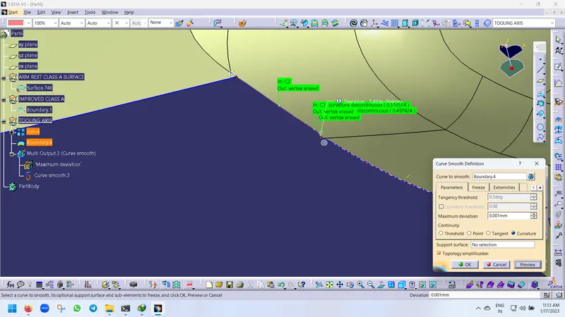
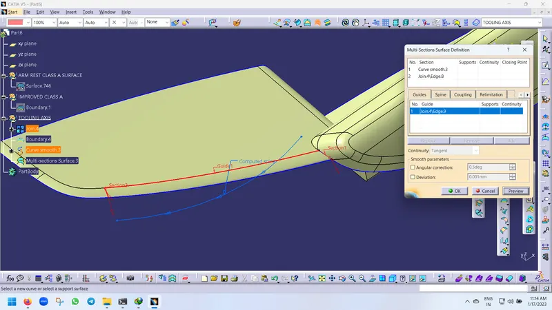
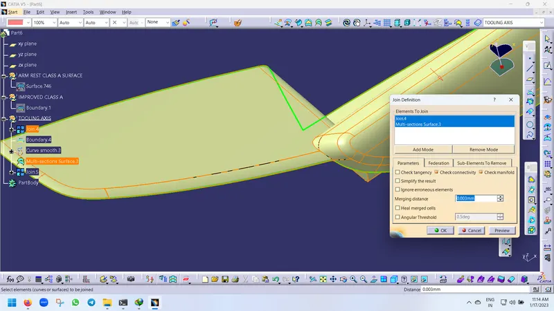
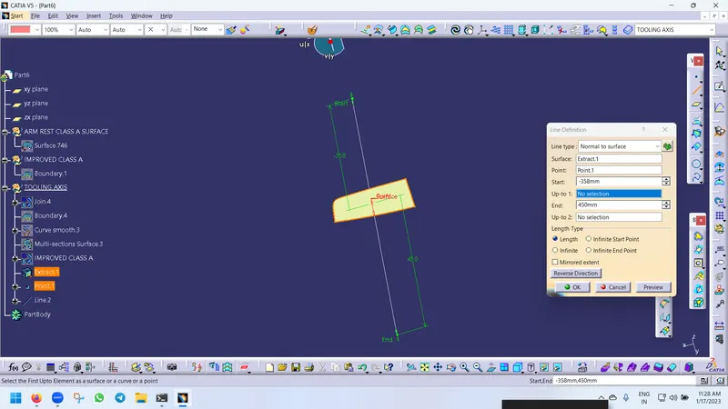
Creation of tooling axis:
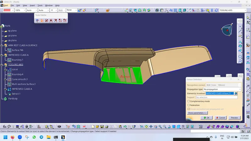
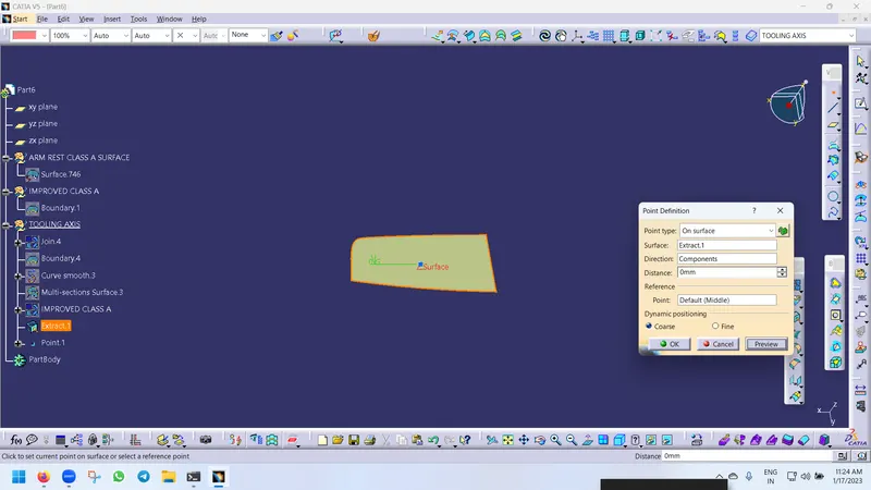
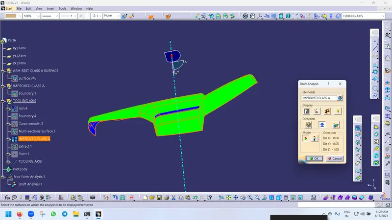
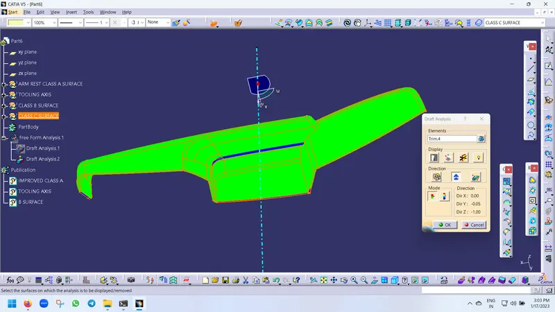
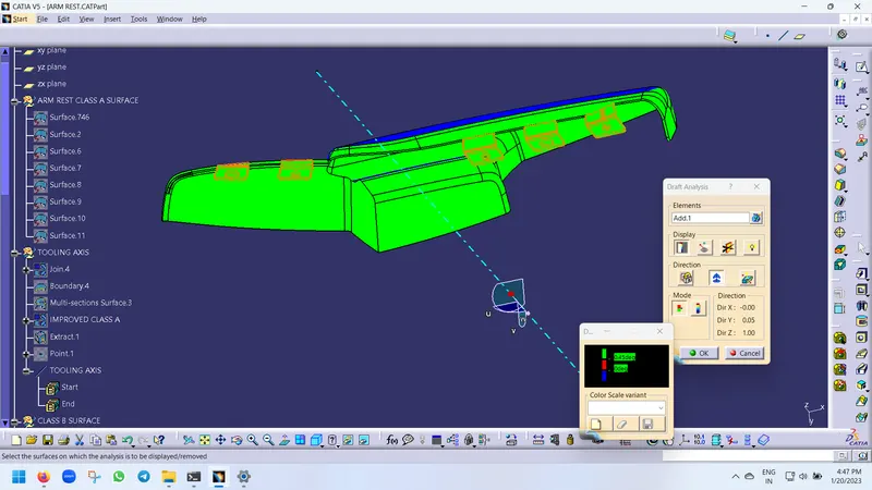
Draft Analysis:
Creation of Class B surface:
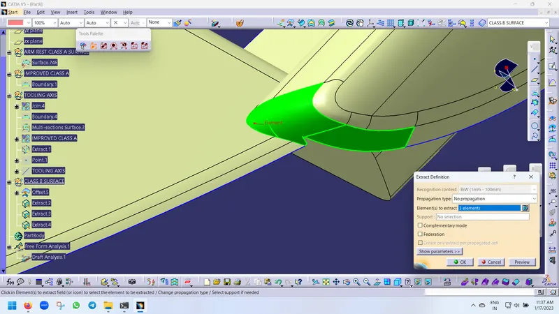
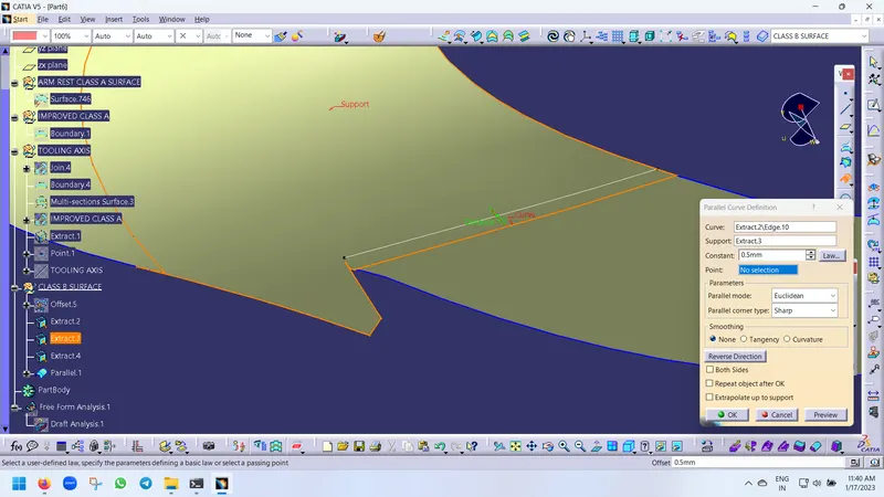
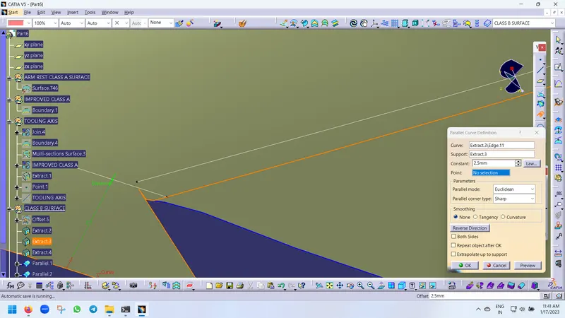
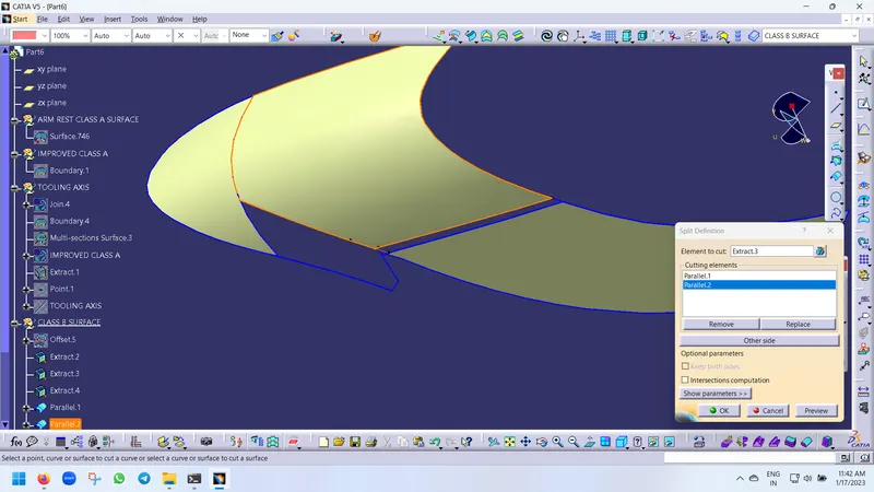
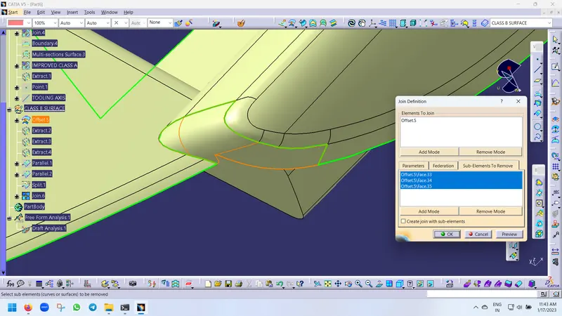
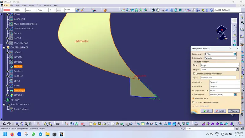
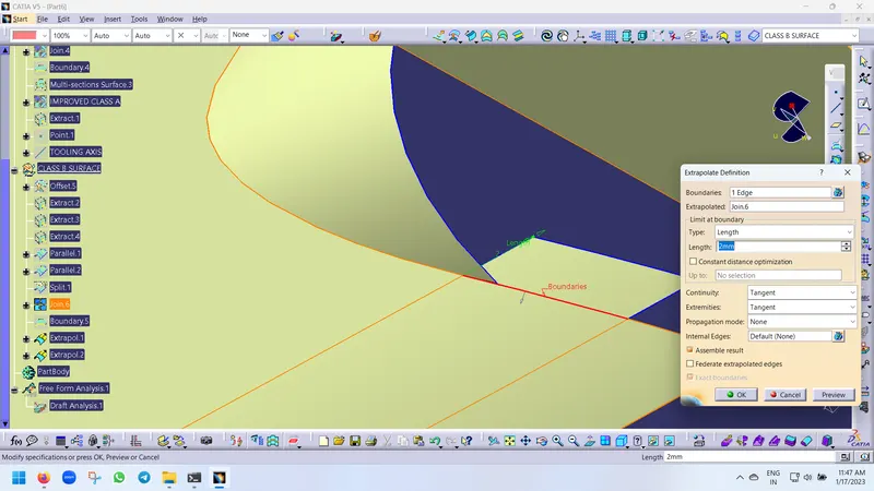
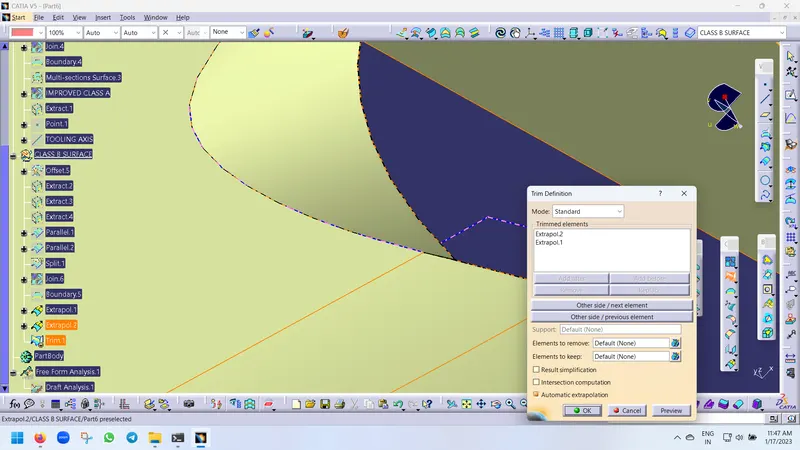
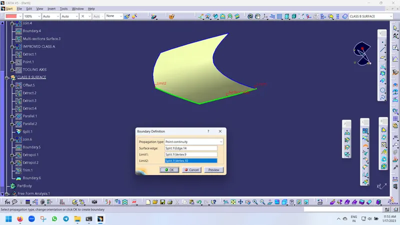
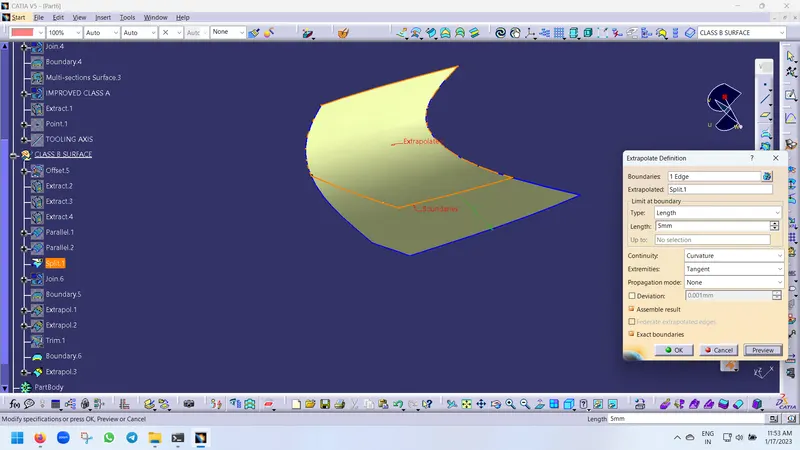
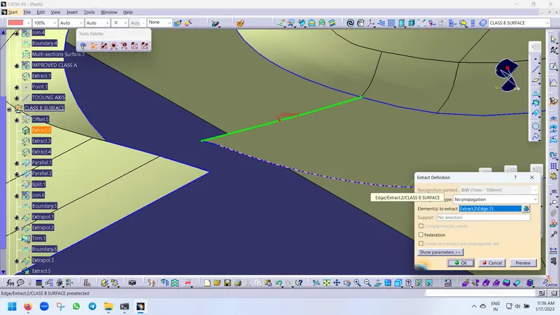
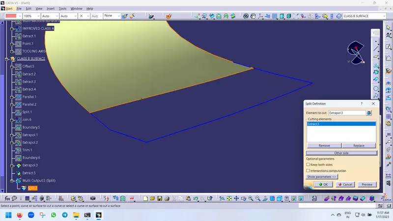
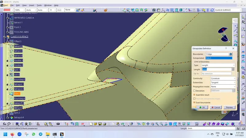
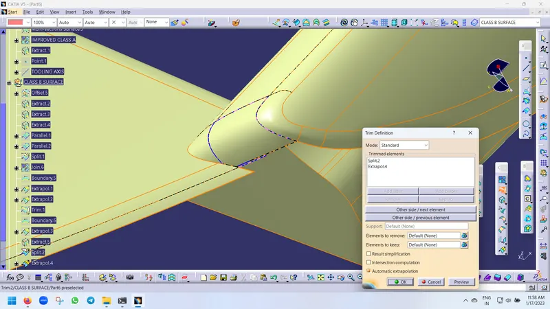
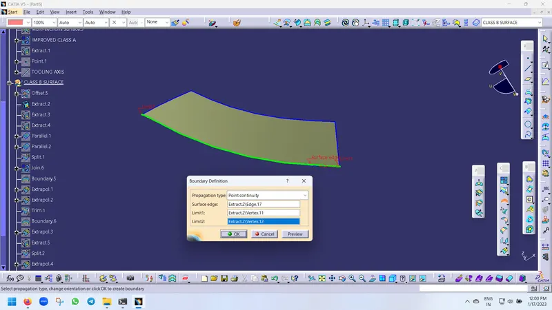
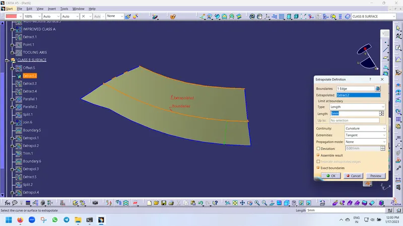
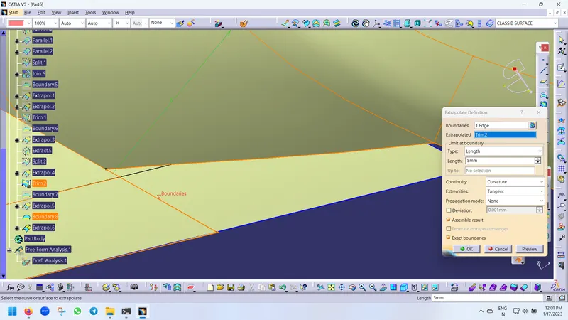
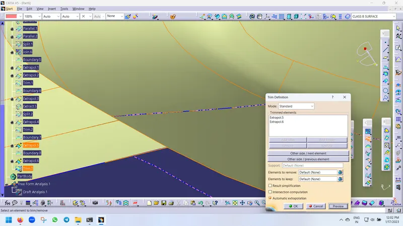
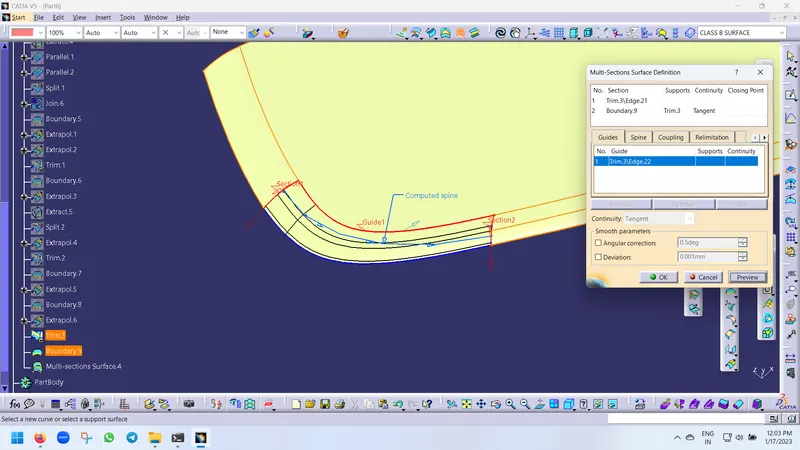
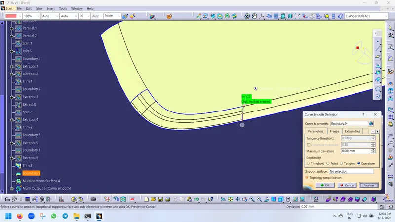
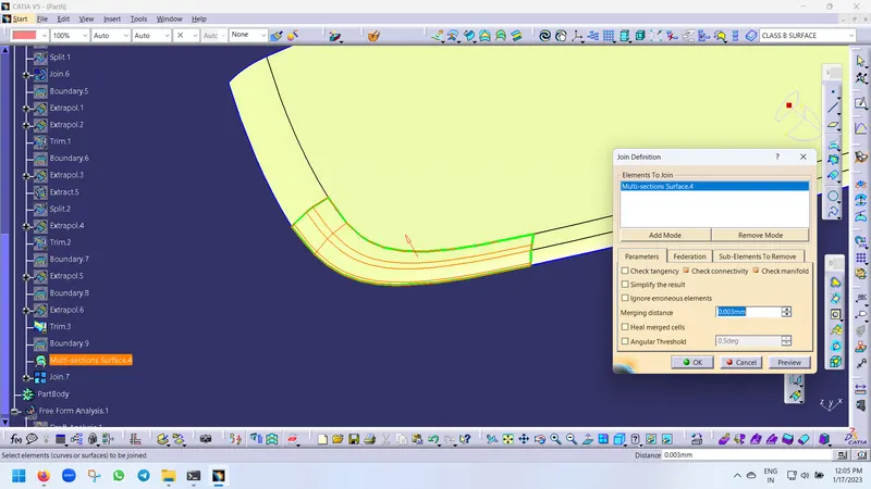
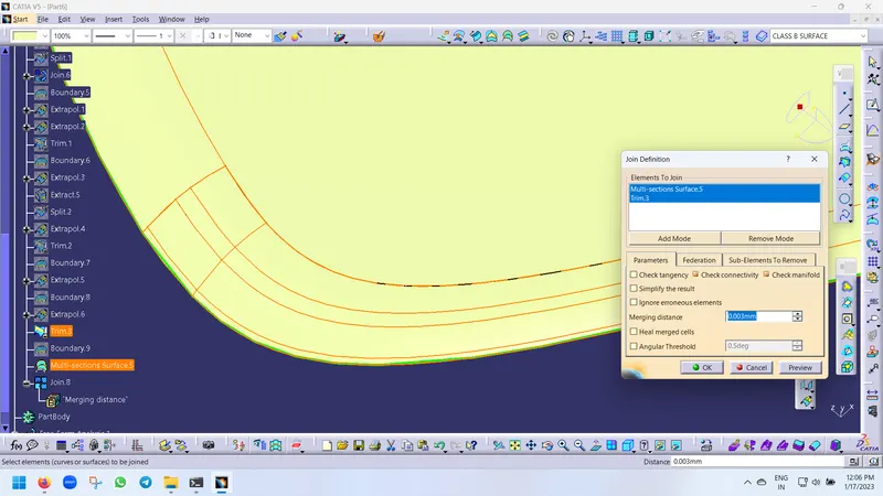
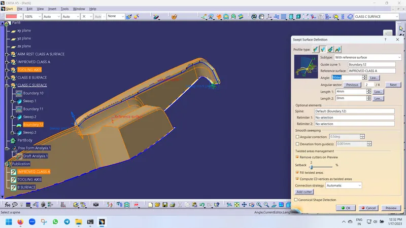
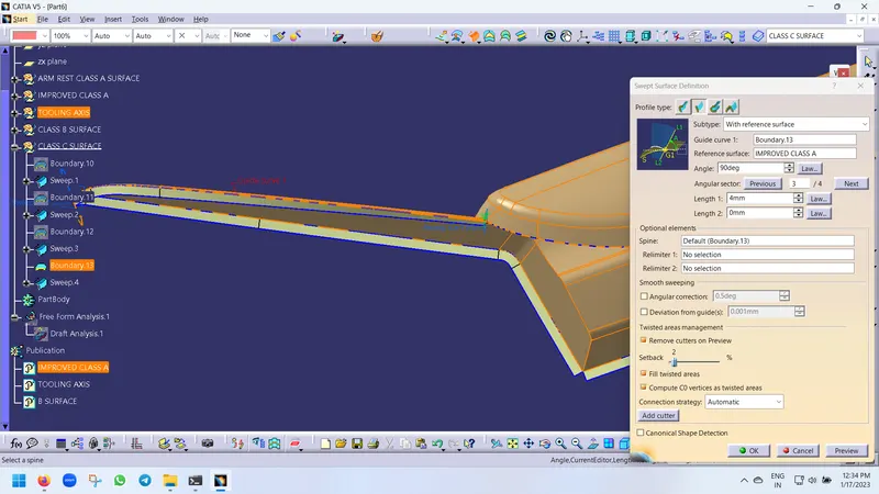
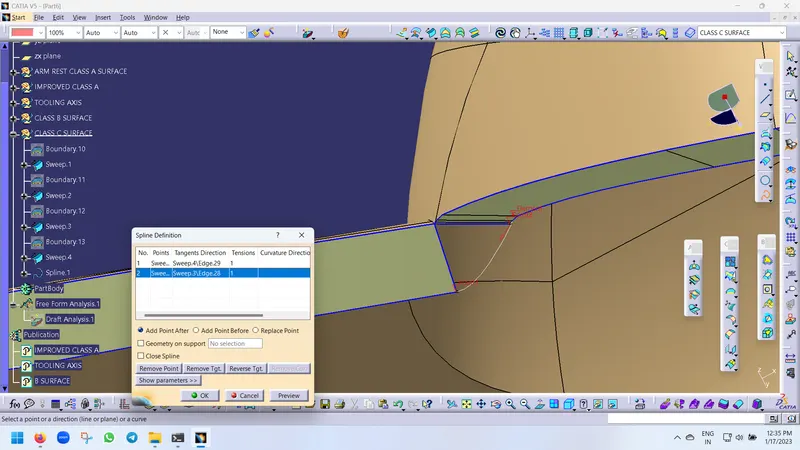
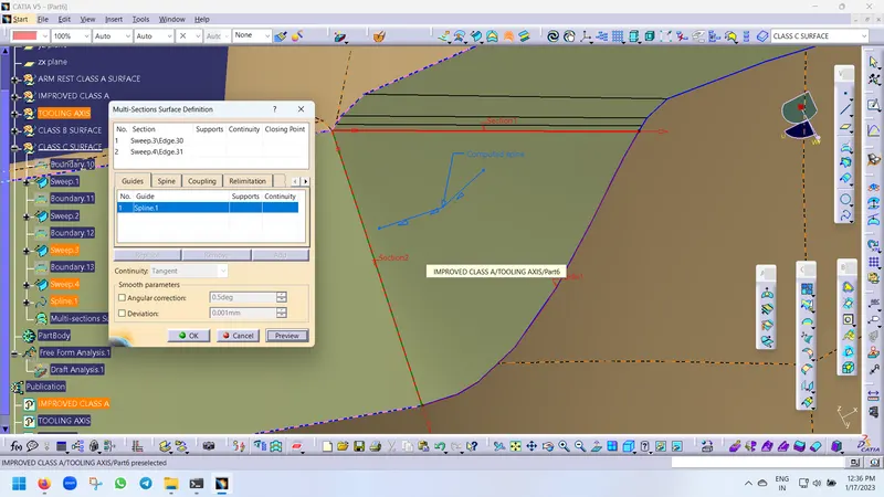
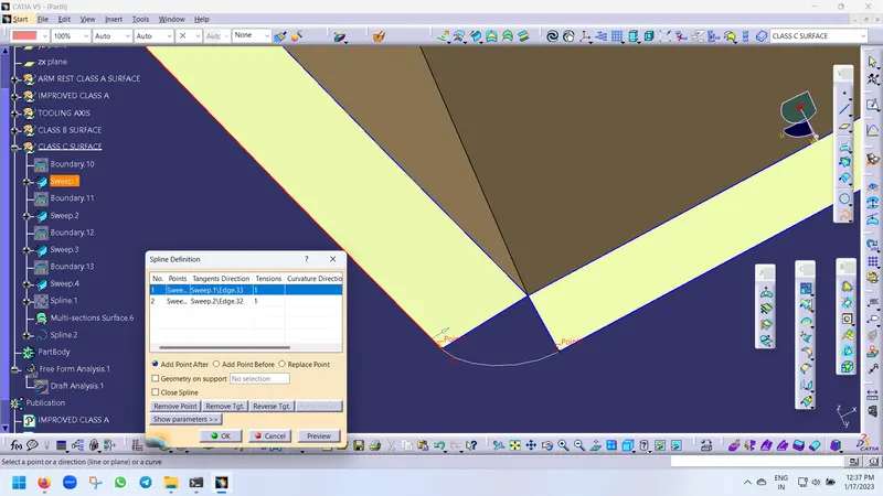
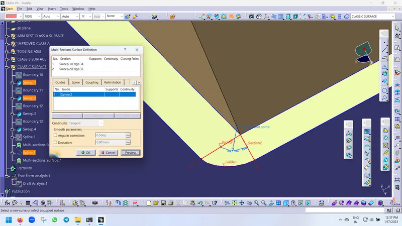
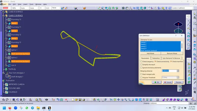
Creation of Class C surface:
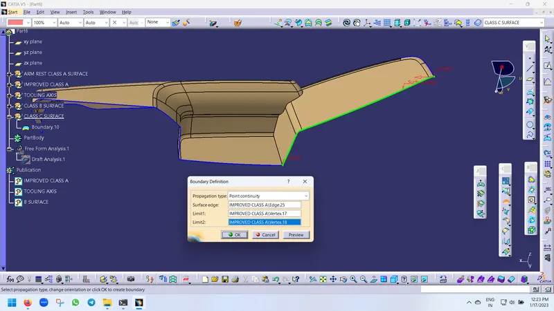
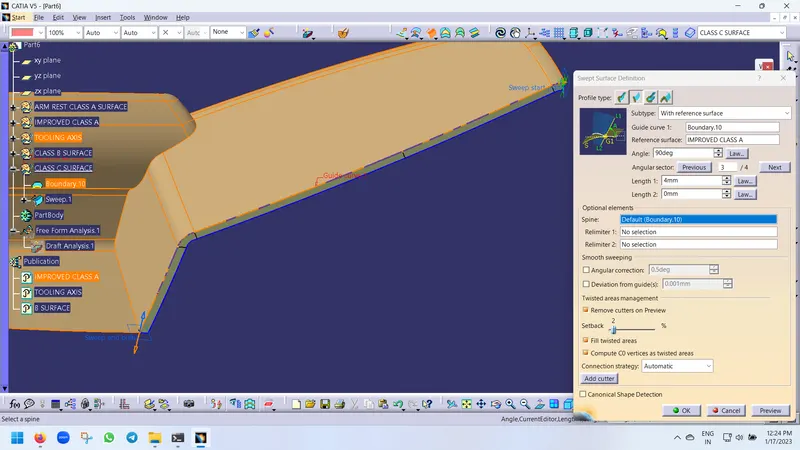
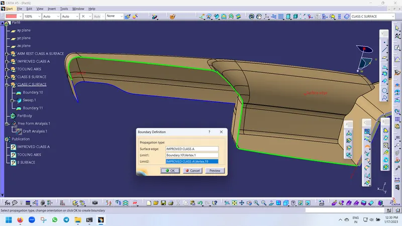
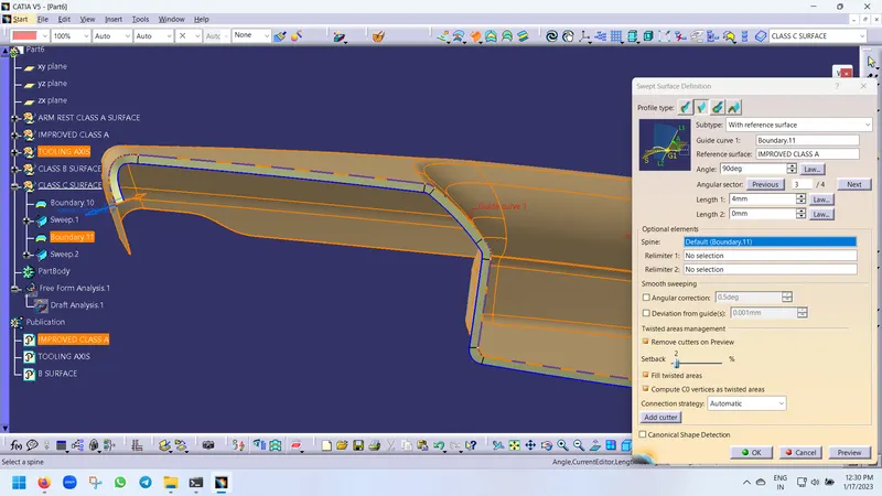
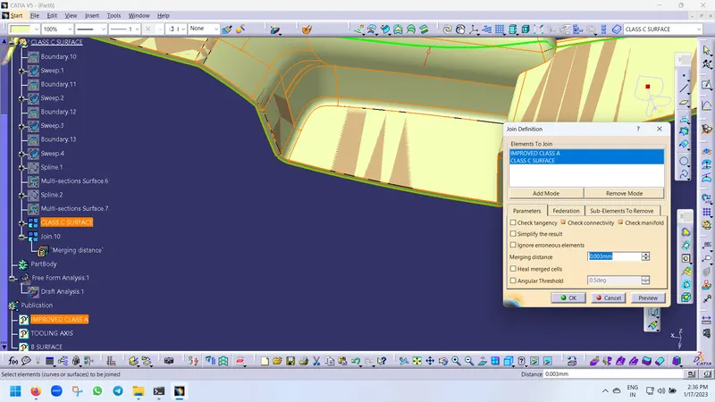
Class A+C:
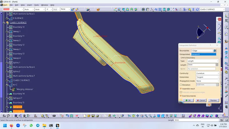
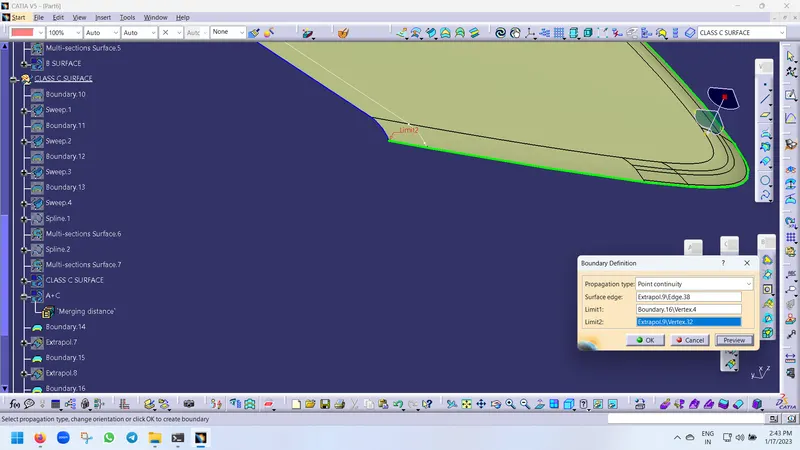
Class B Extrapolation:
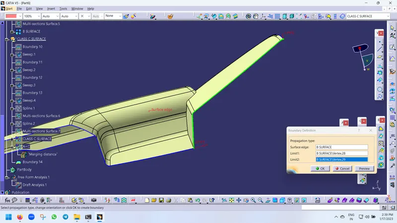
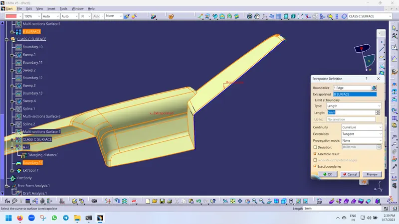
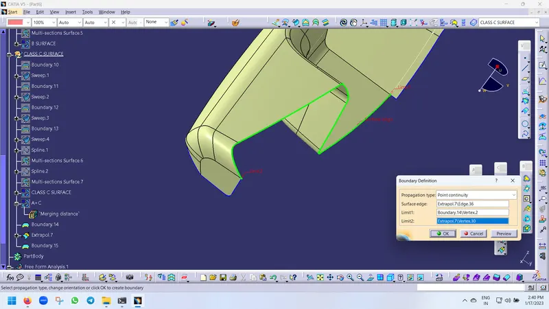
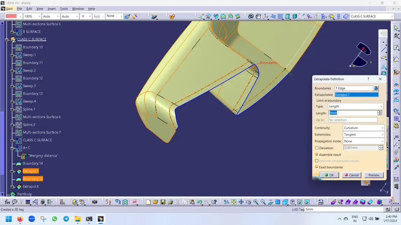
Final part:

Final draft analysis:
2. BOTTLE HOLDER:
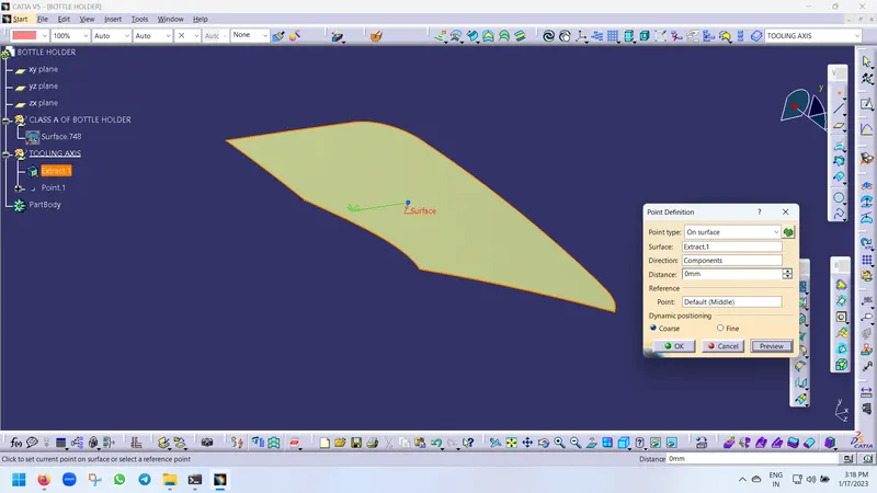
Creation of tooling axis:
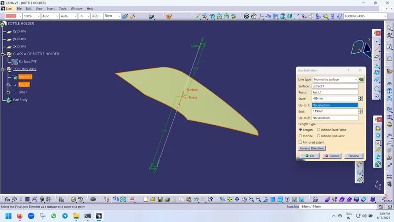
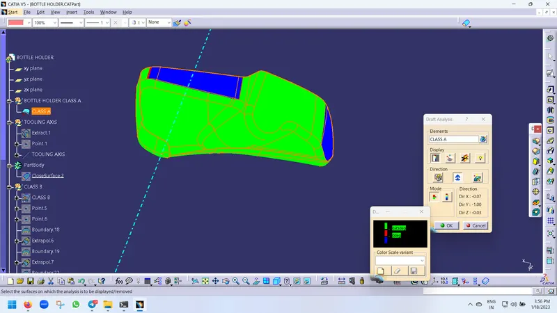
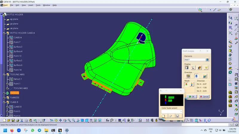
Draft analysis:
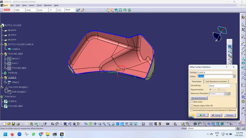
Class B surface creation:
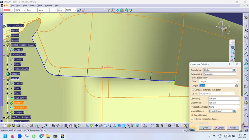
Extrapolation of Class B:
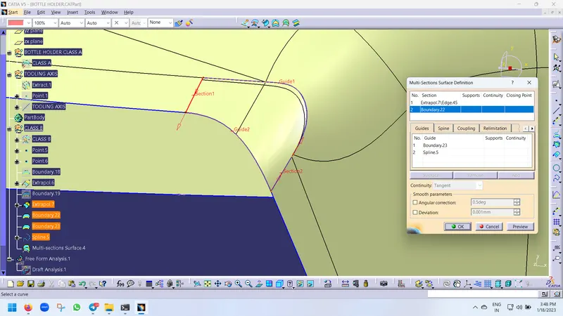
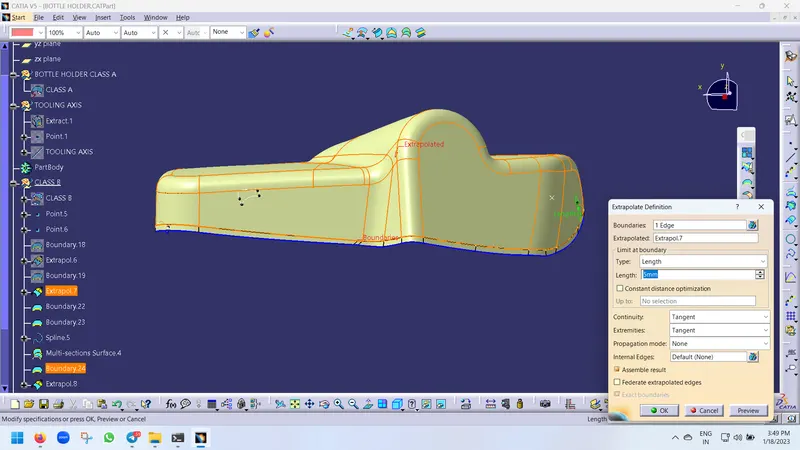
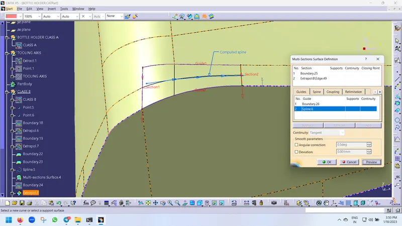
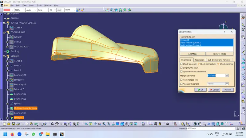
Creation of Class C Surface:
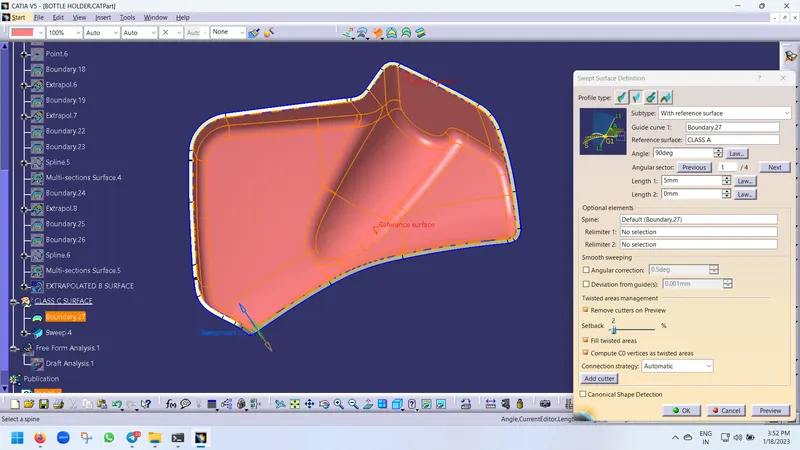
Join of Class A+C:
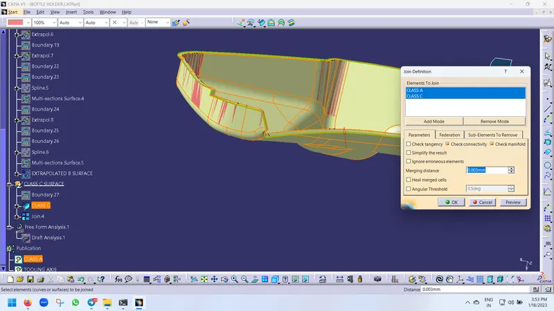
Final part:
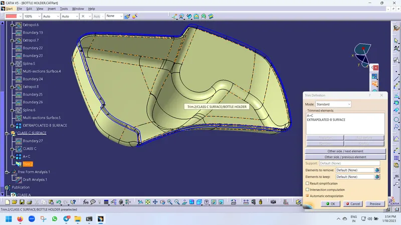
Final draft analysis:

3. LOWER SUBSTRATE:
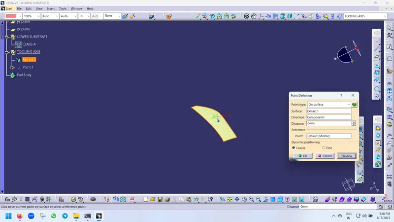
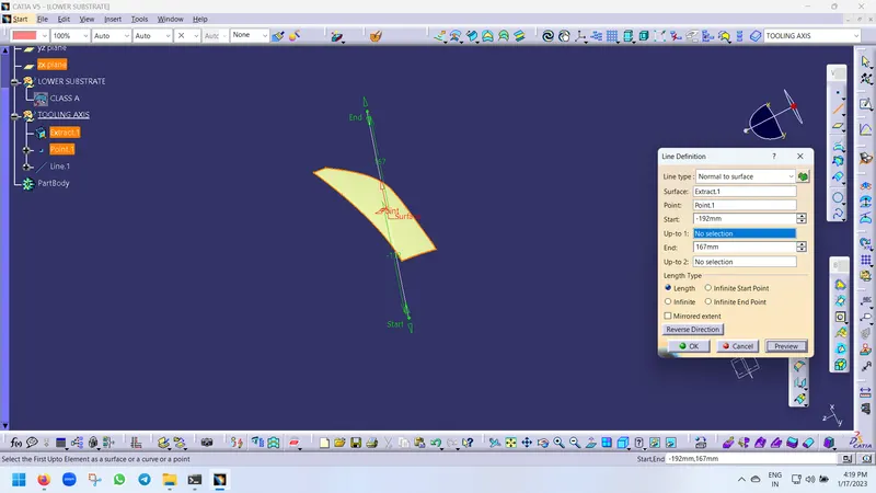
Creation of tooling axis:
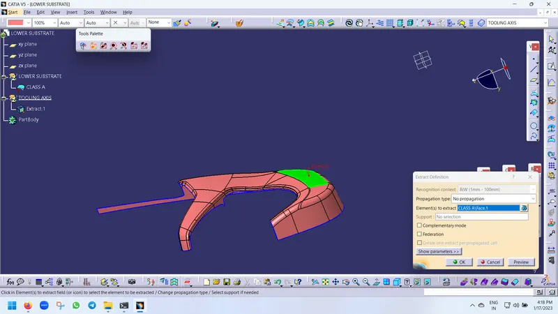
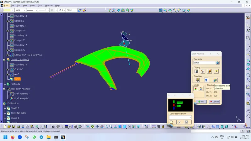
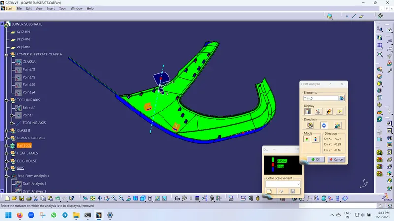
Draft analysis:
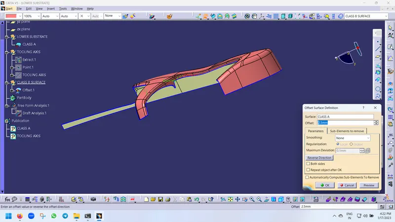
Creation of Class B:
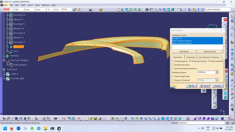
Creation of class c surface:
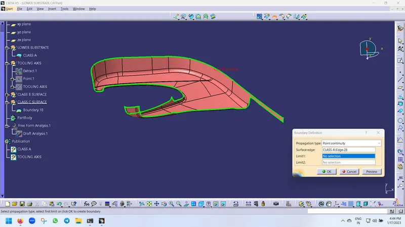
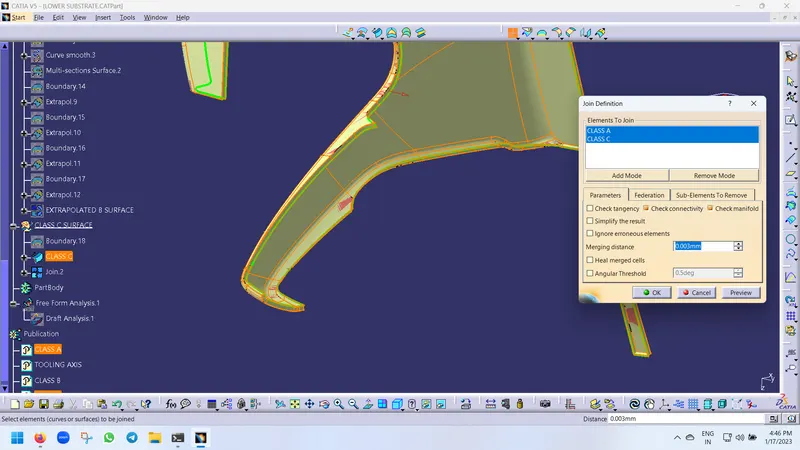
Final part:
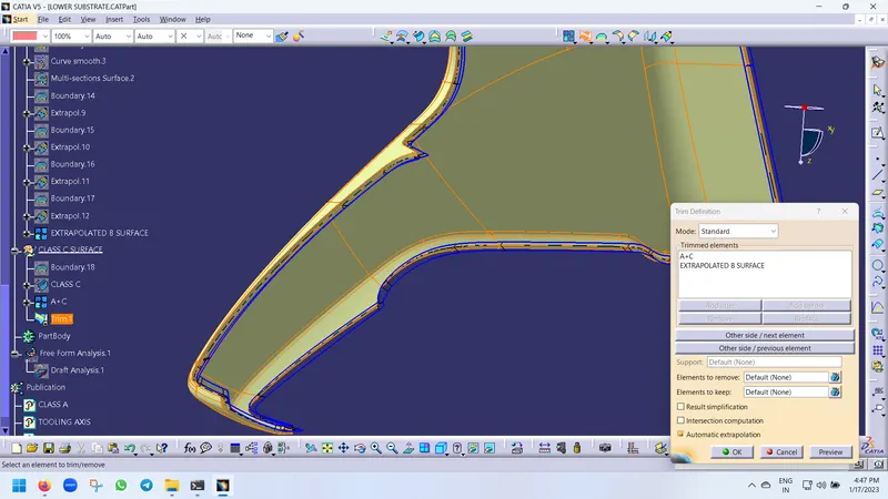
Final draft analysis:
4. MAP POCKET:
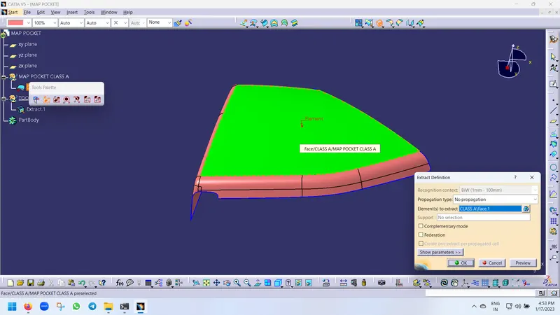
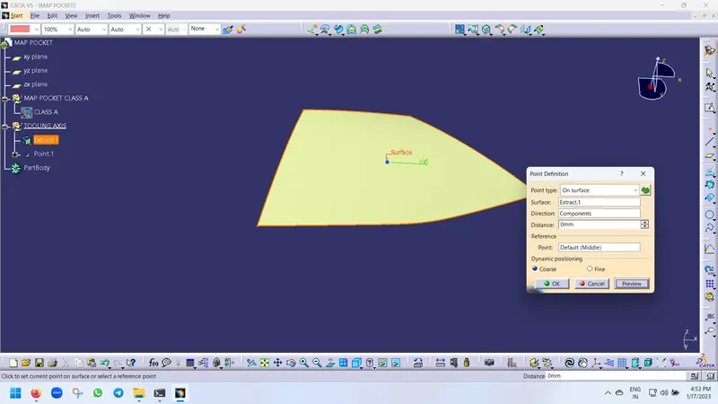
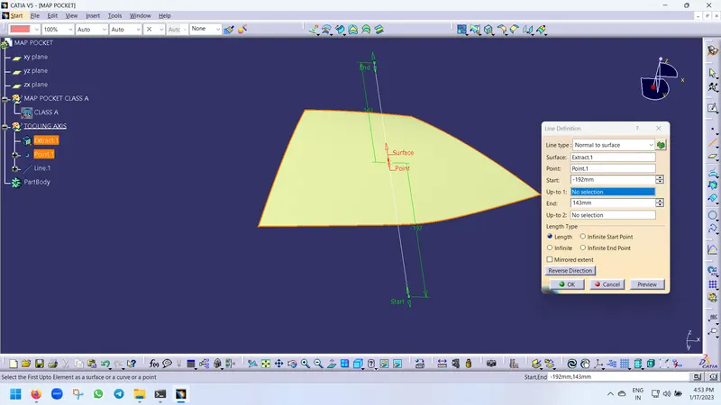
Creation of tooling axis:
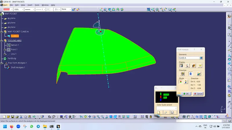
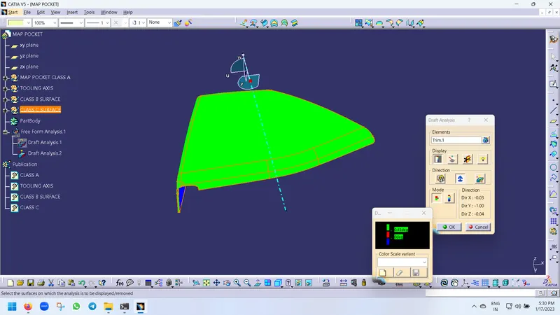
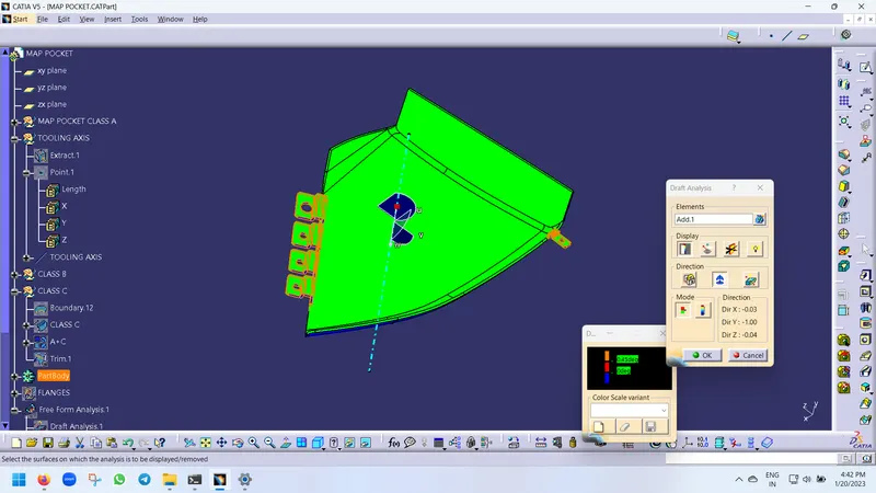
Draft analysis:
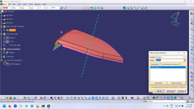
Creation of class B surface:
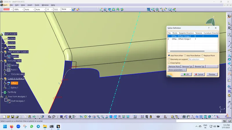
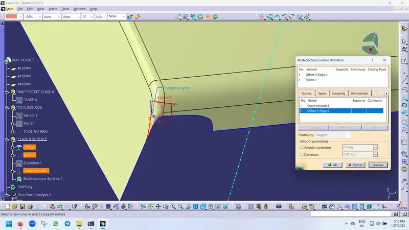
Creation of class c surface:
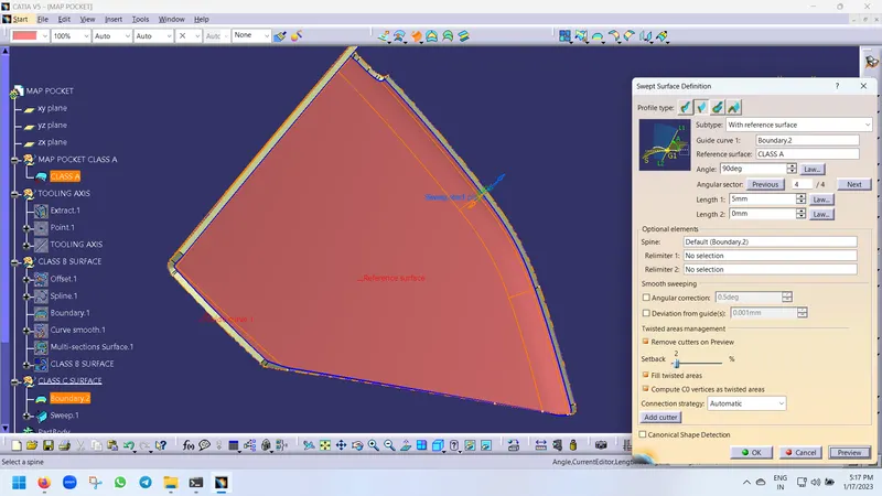
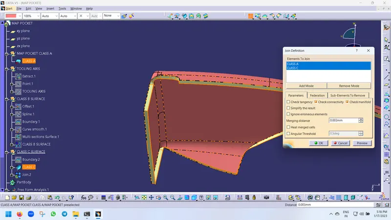
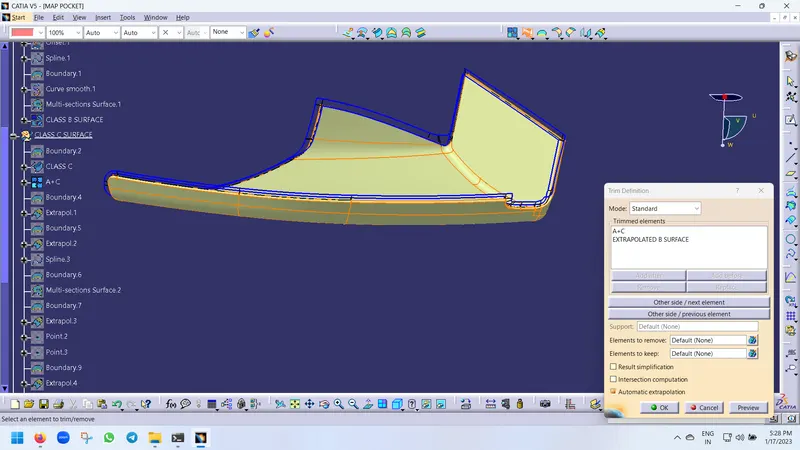
Final part:
Draft analysis:
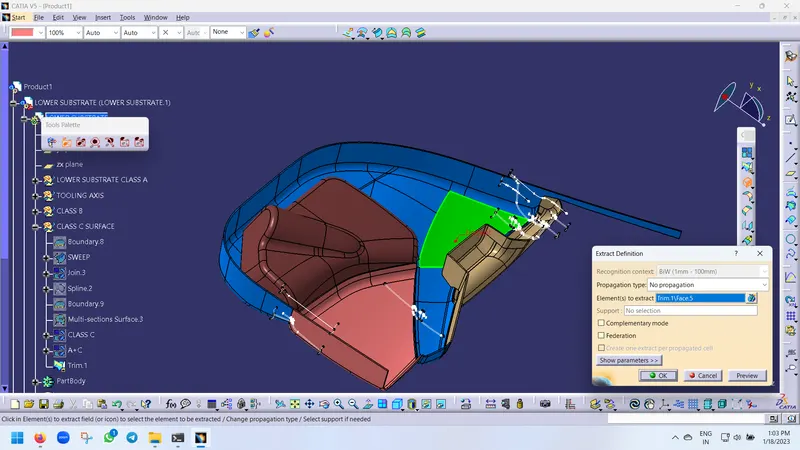
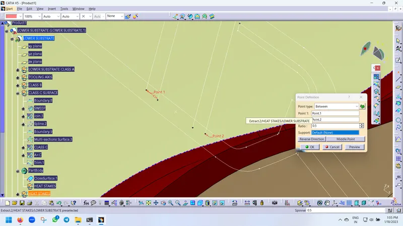
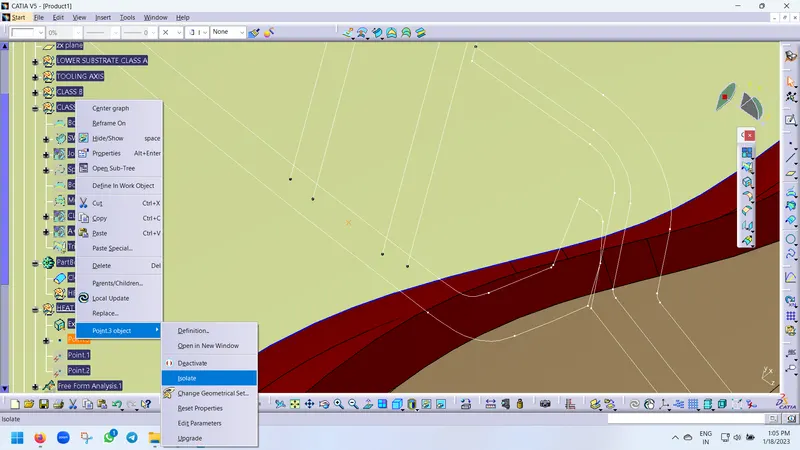
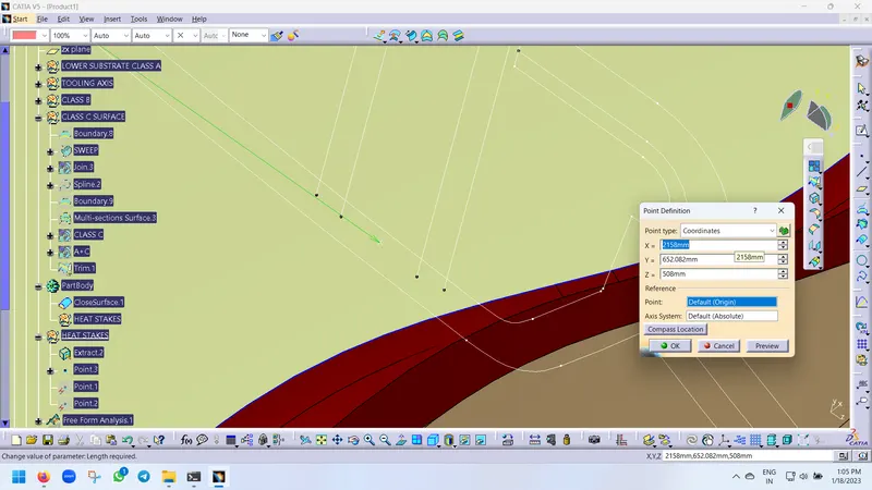
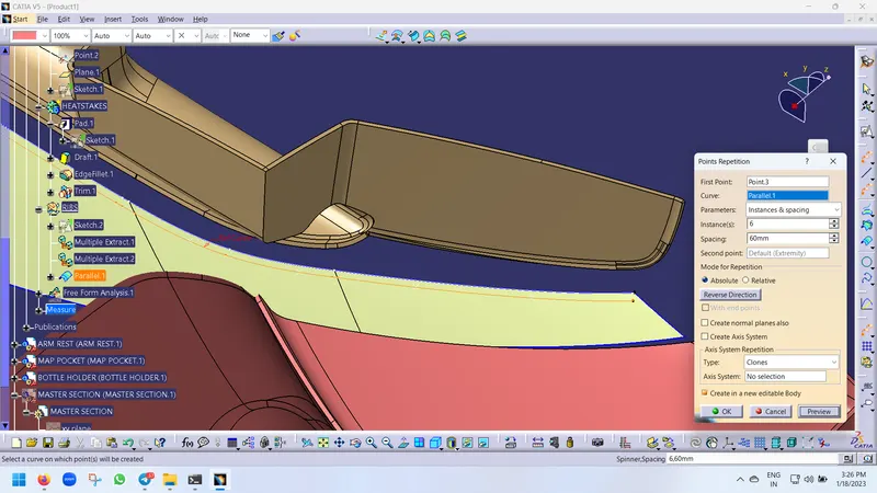
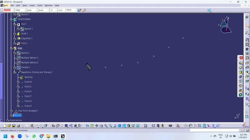
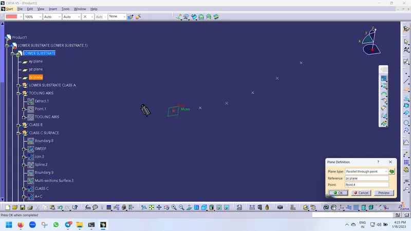
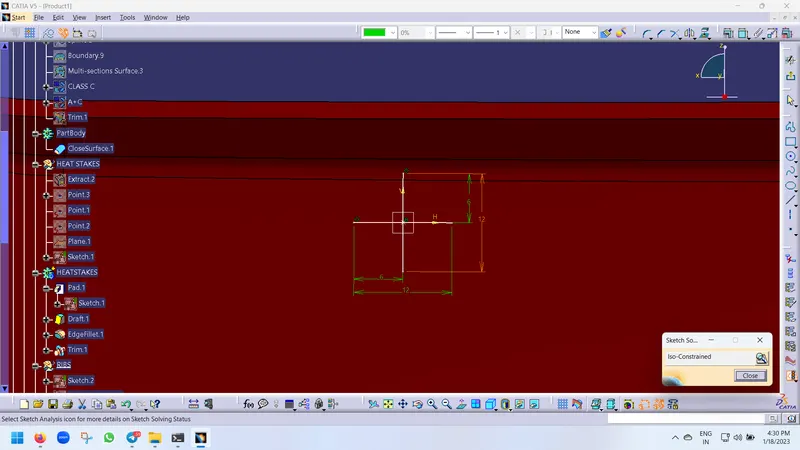
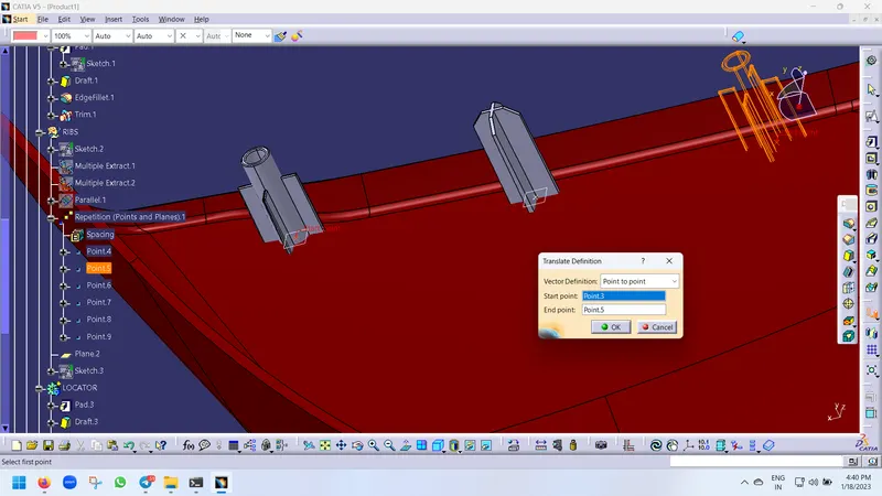
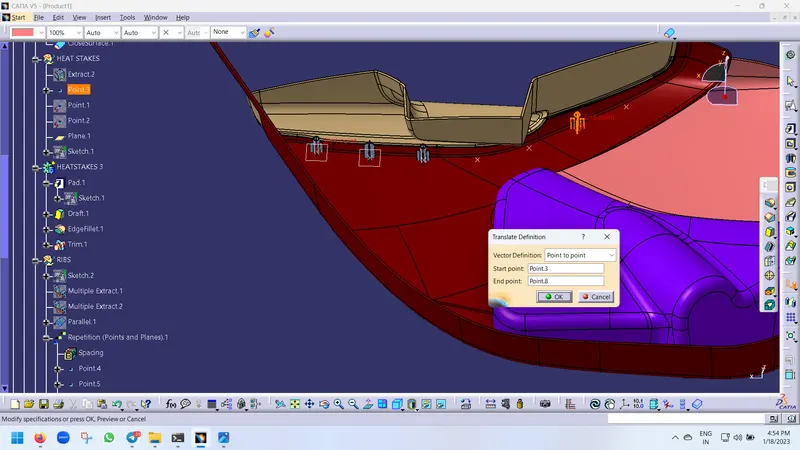
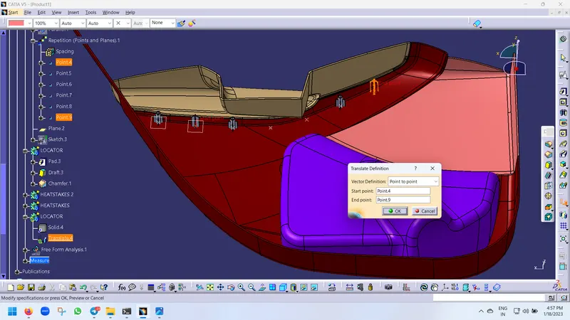
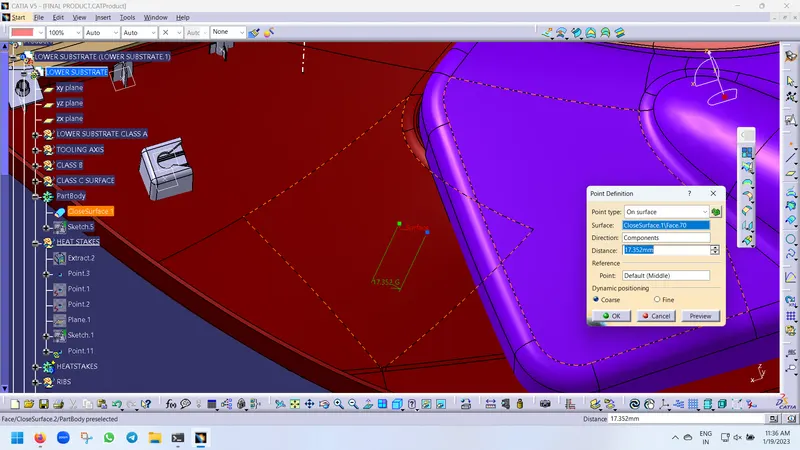
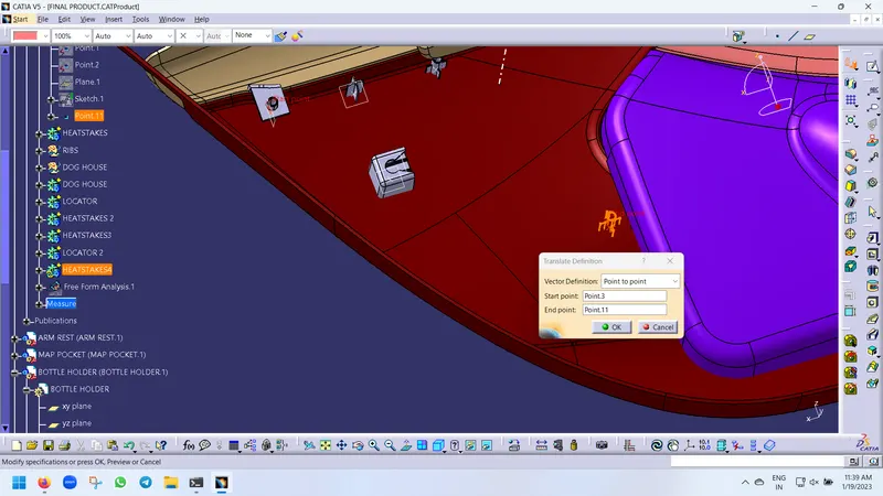
CREATION OF HEAT STAKES IN LOWER SUBSTRATE:
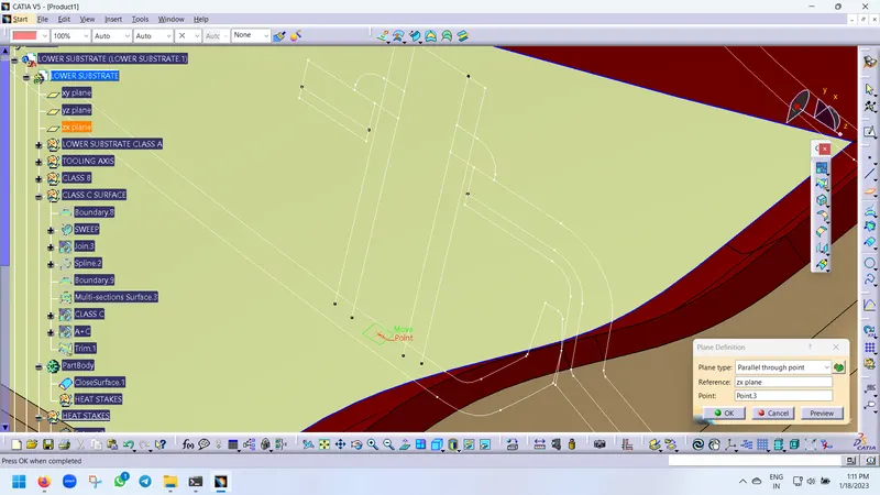
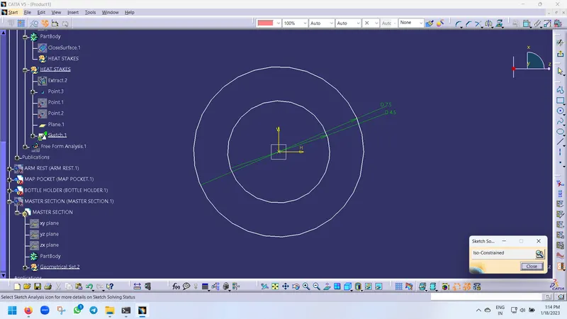
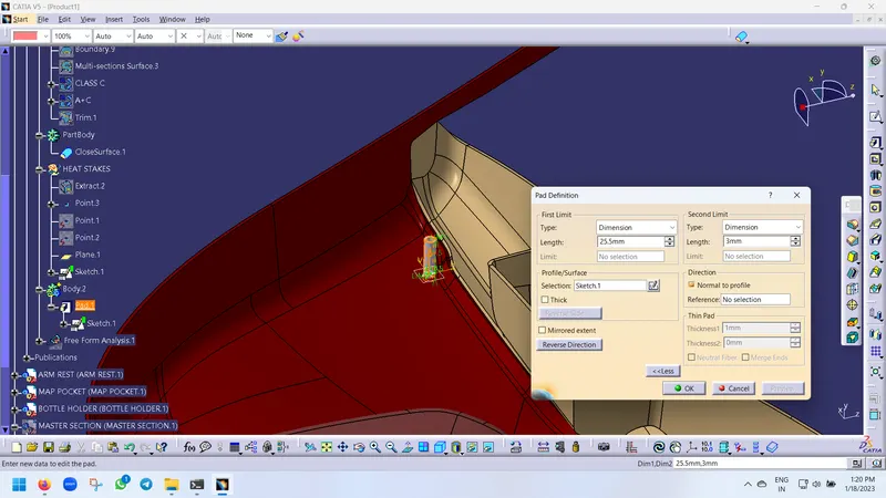
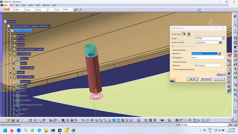
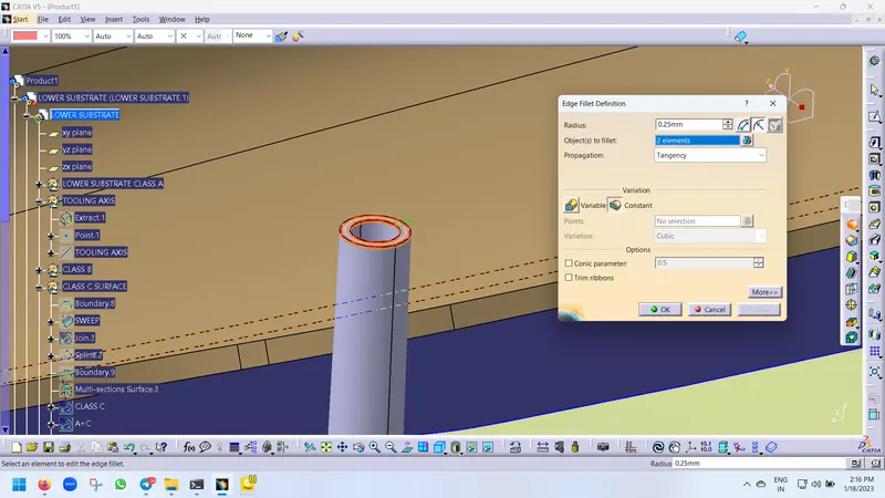
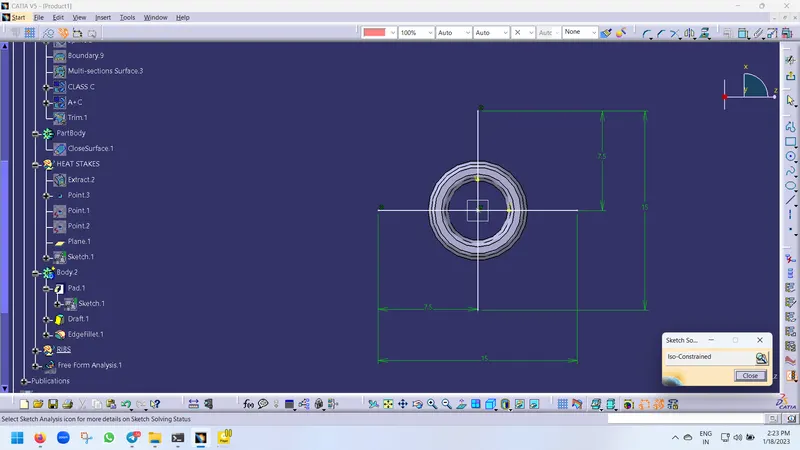
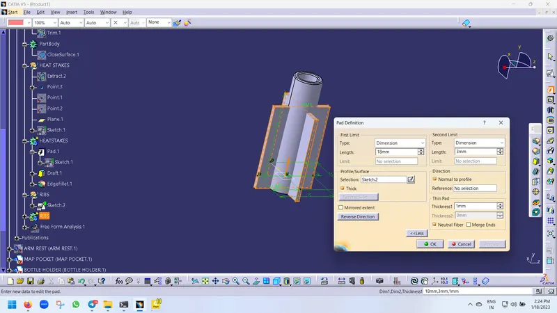
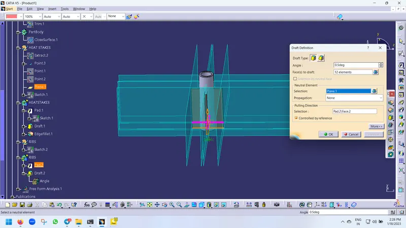
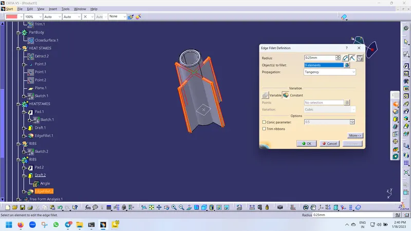
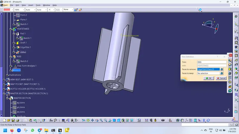
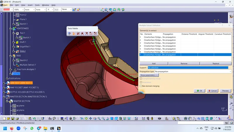
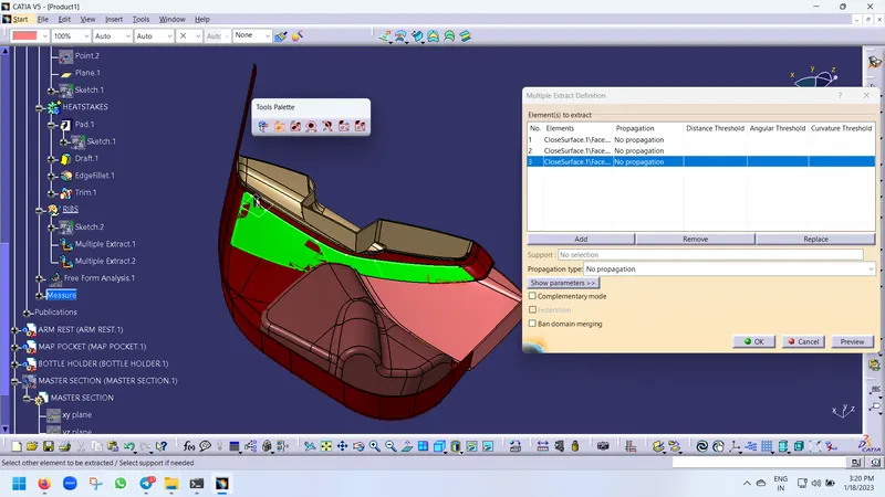

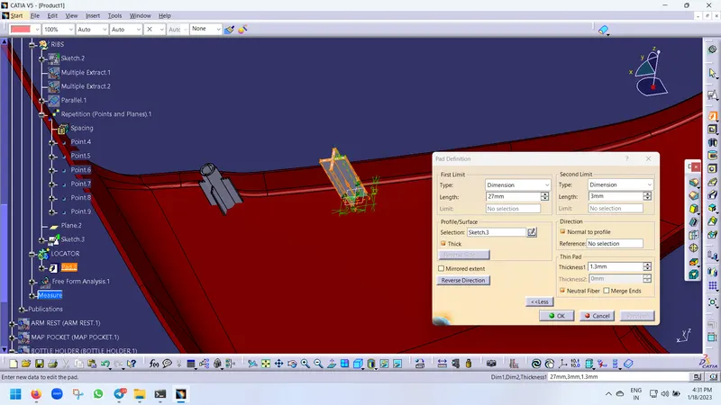
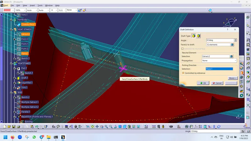
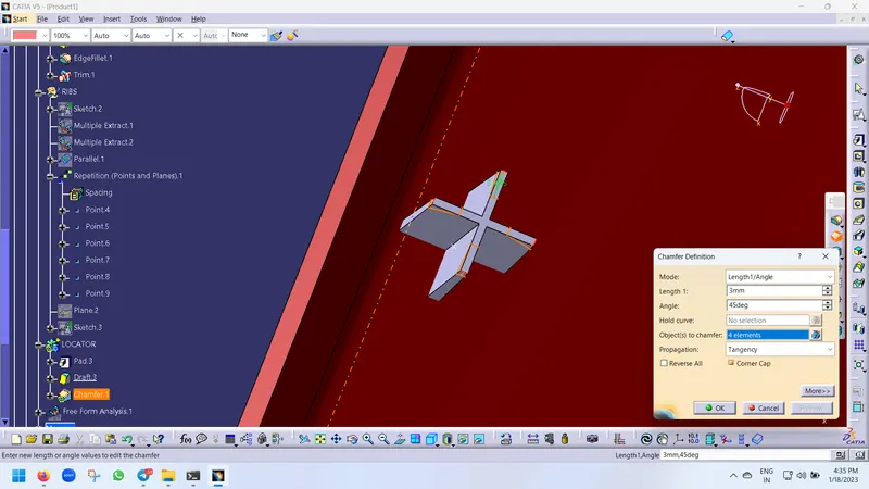
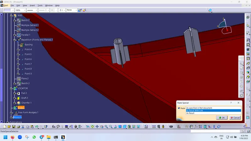
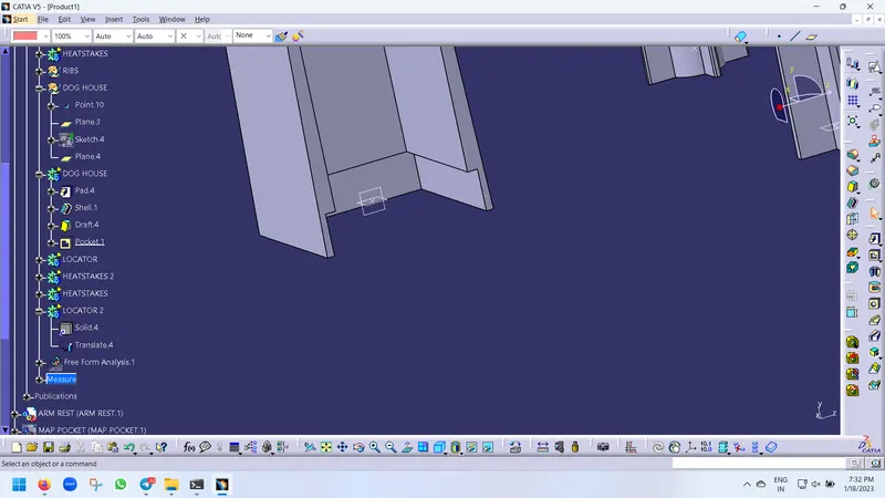
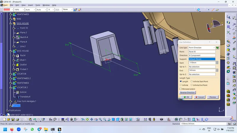
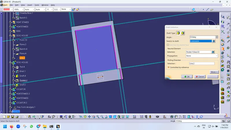
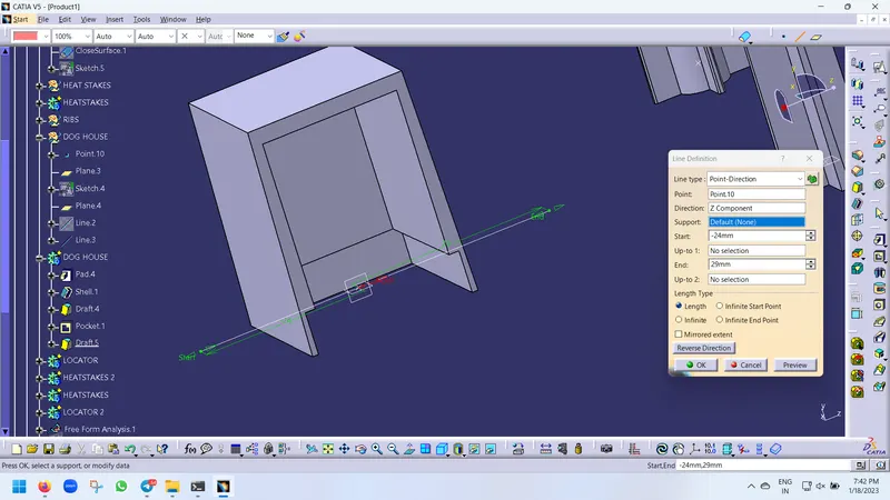
Creation of Dog house in Lowersubstrate:
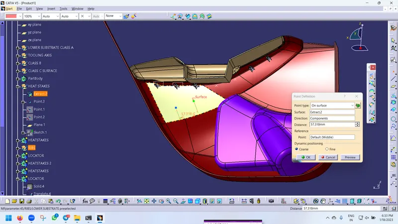
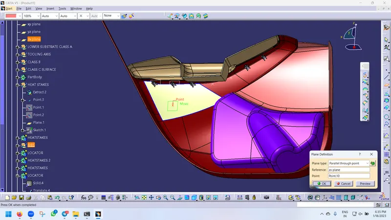
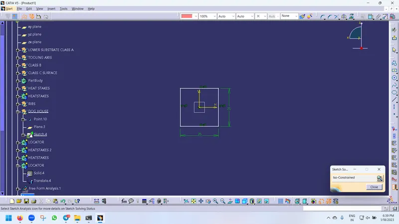
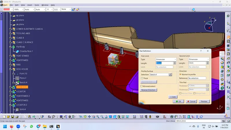
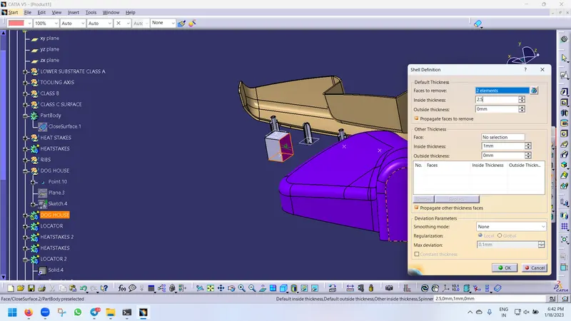
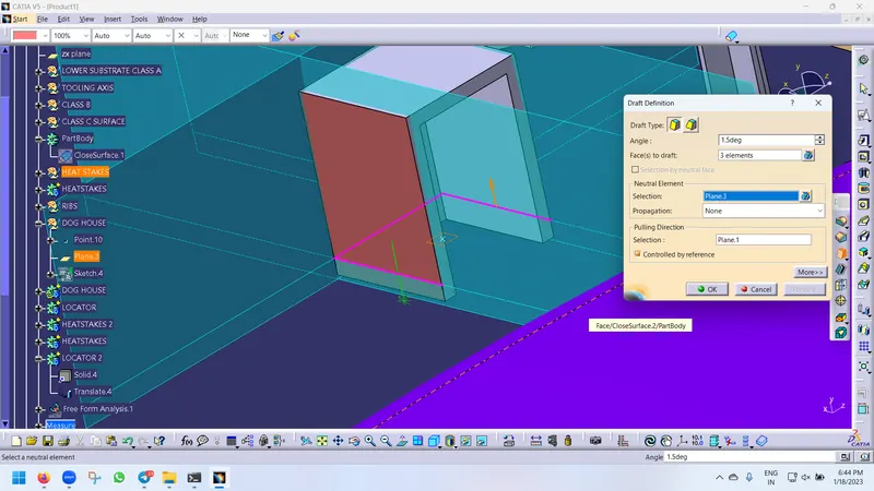
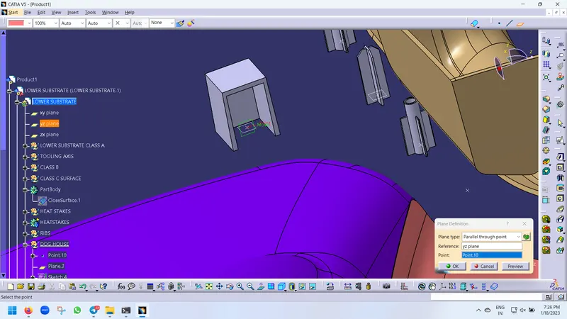
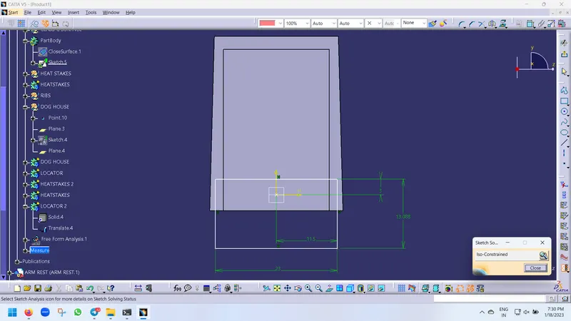
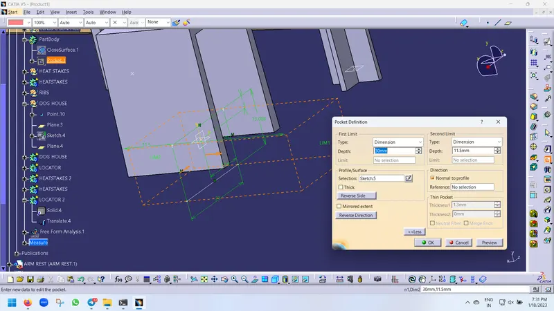
Creation of Ribs in the dog house:
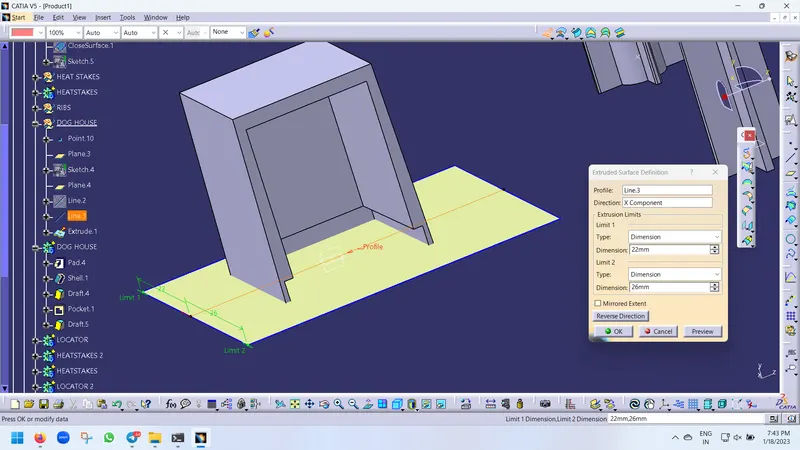
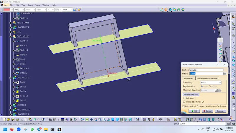
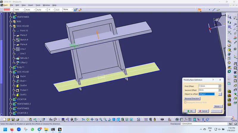
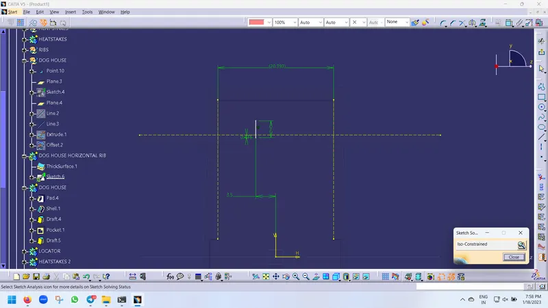
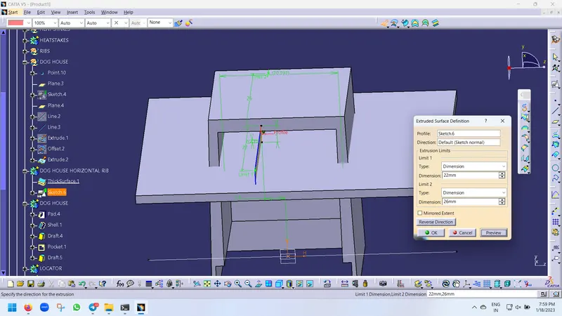
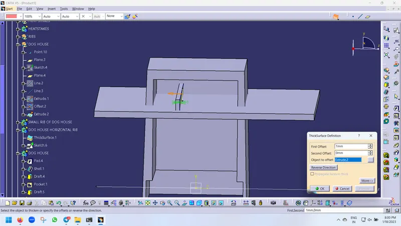
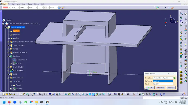
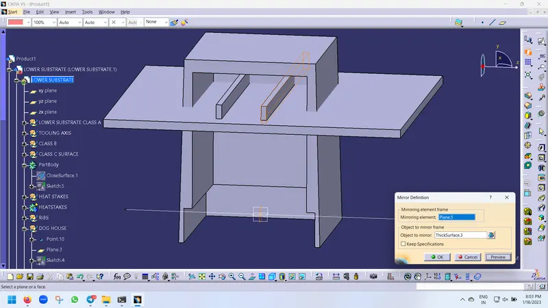
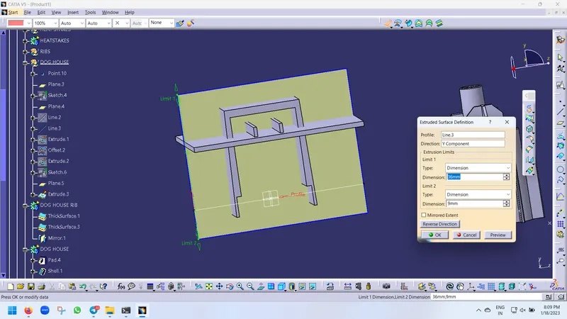
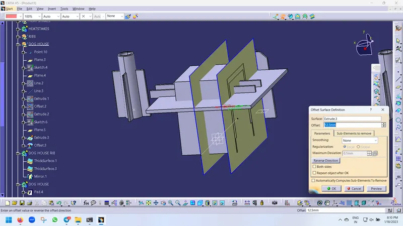
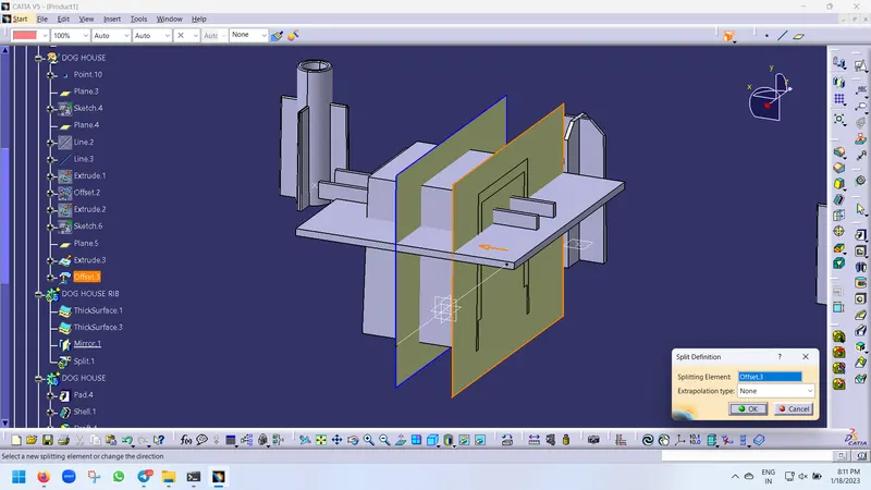
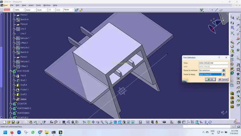
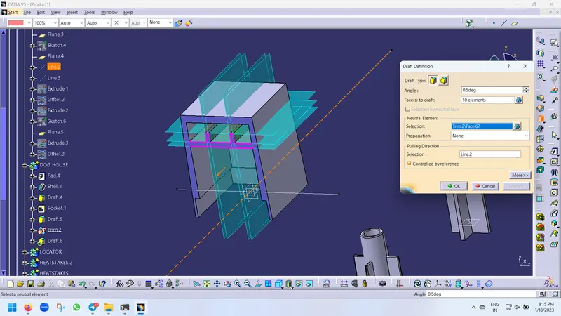
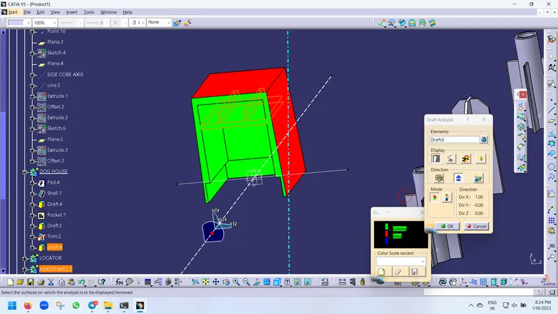
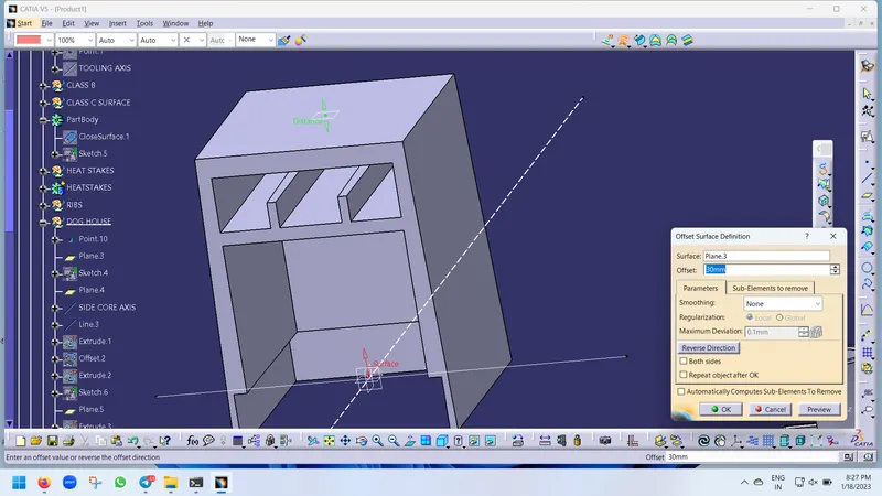
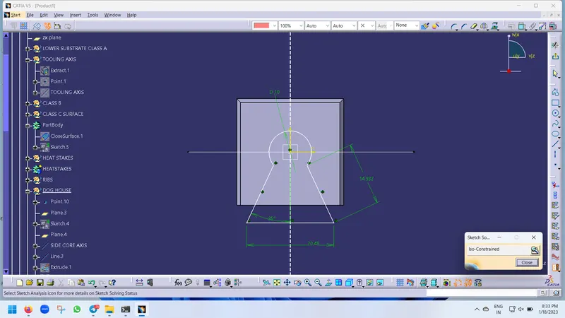
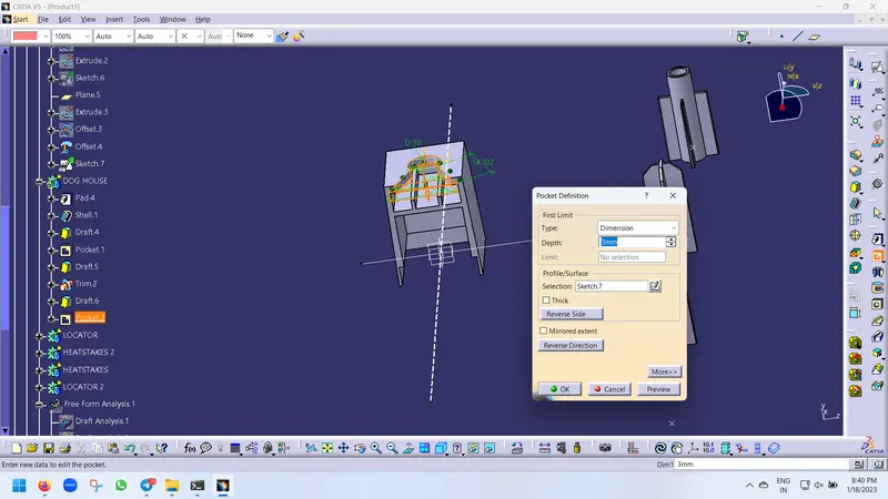
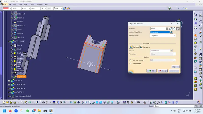
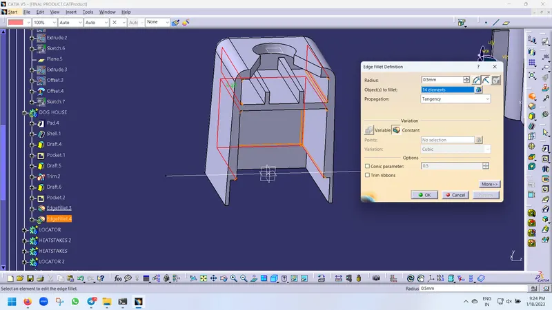
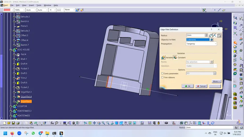
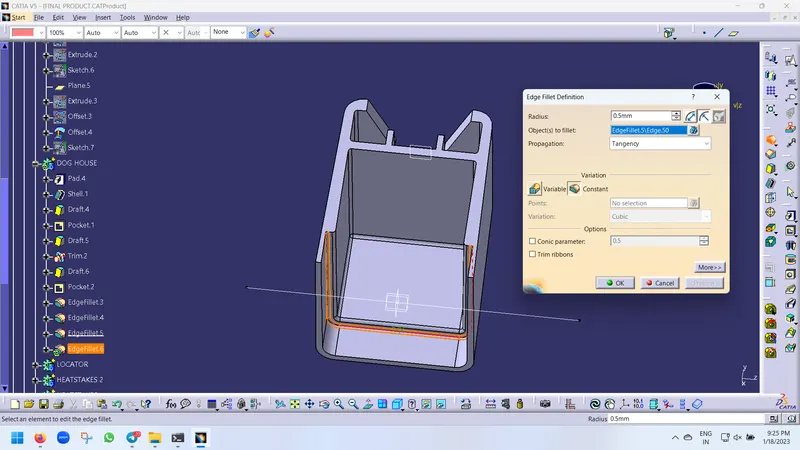
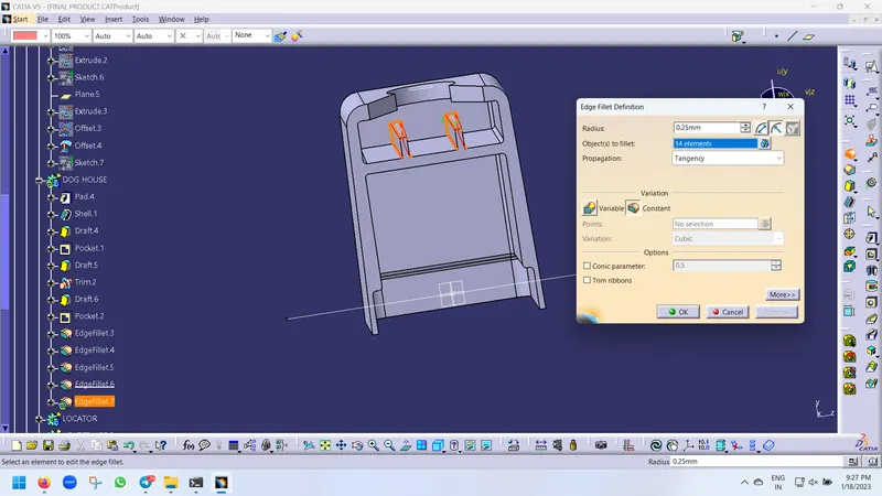
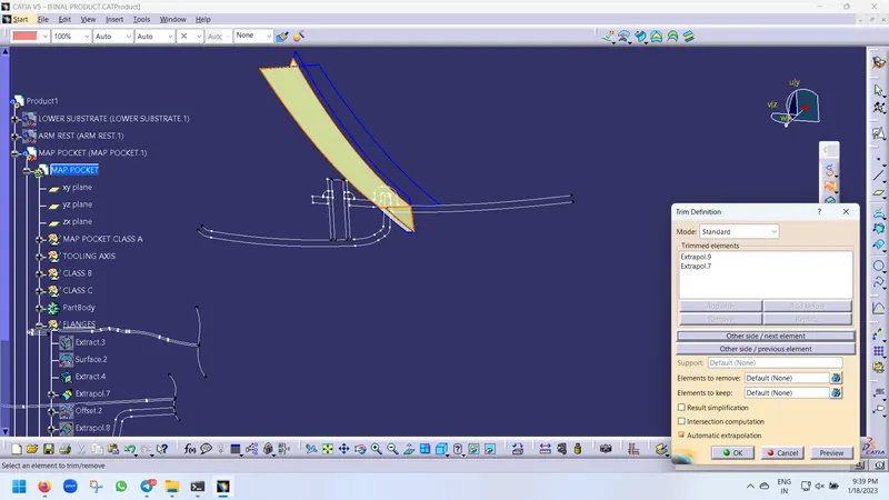
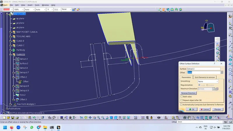
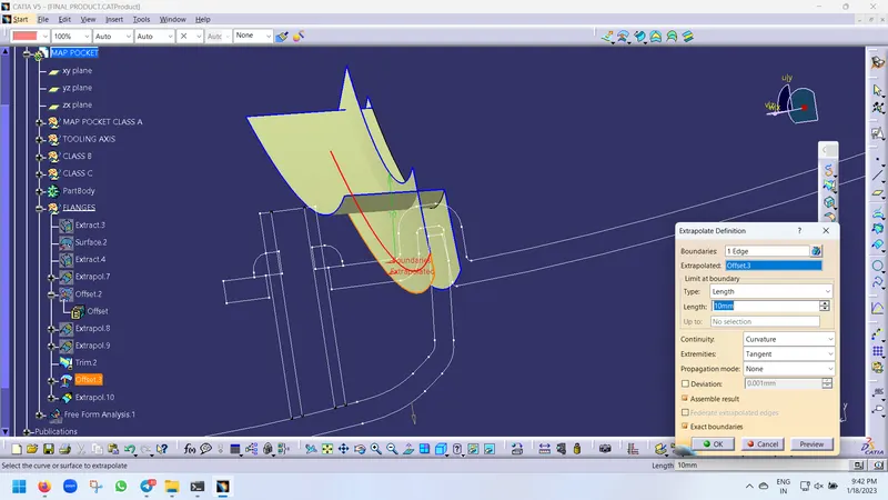
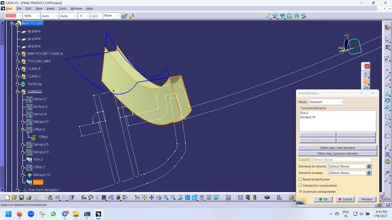
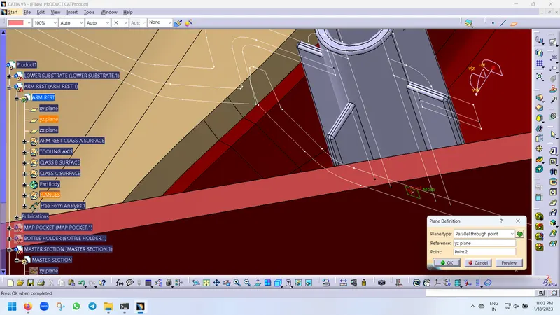
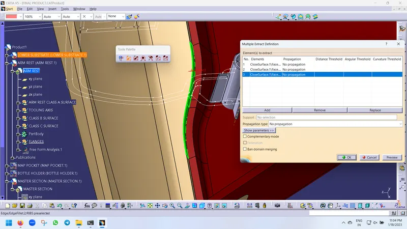
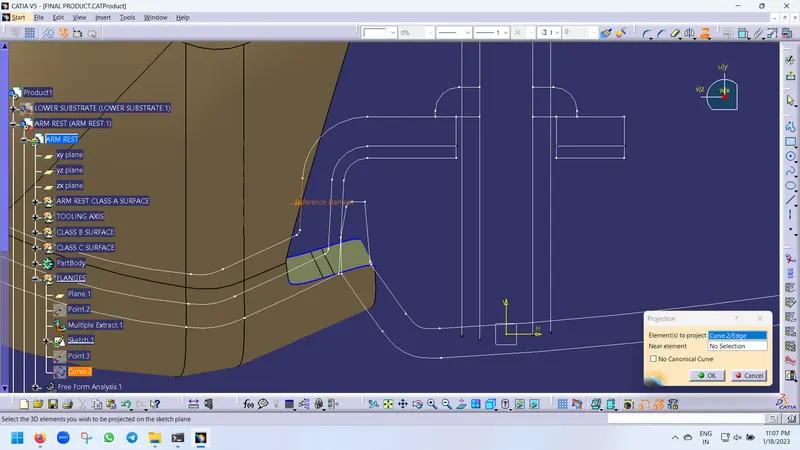
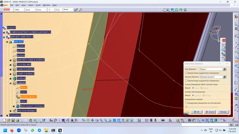
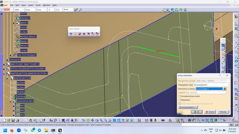
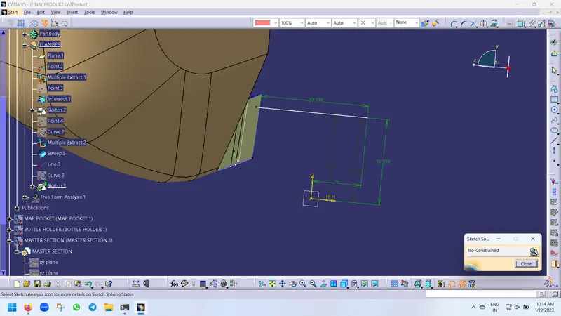
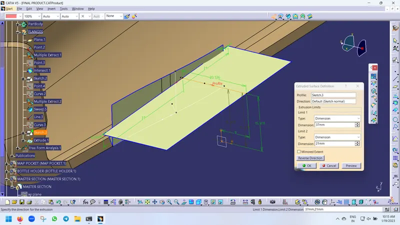
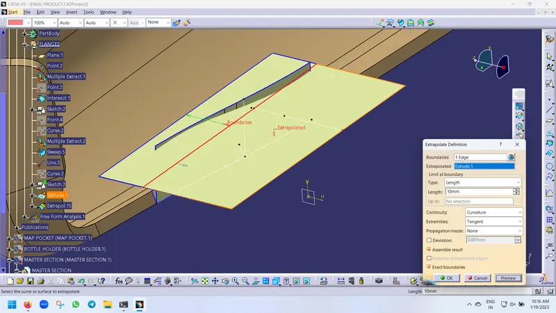
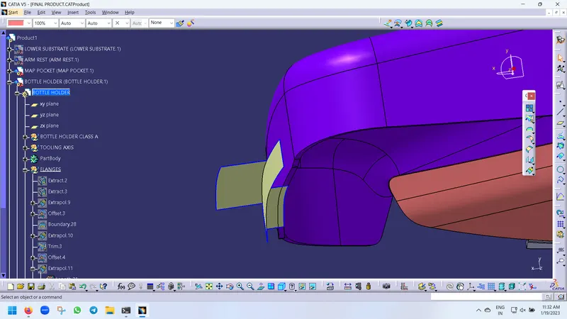
Creation of Flanges:
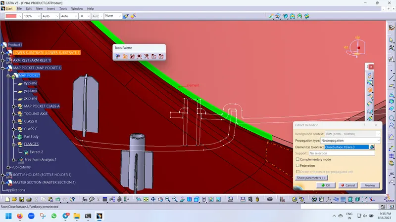
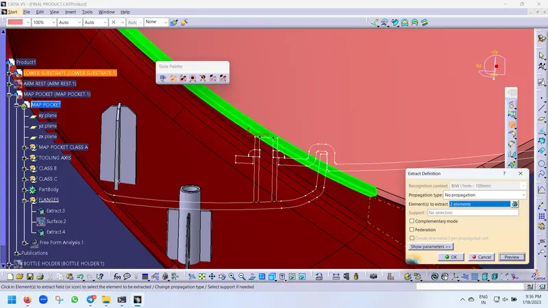
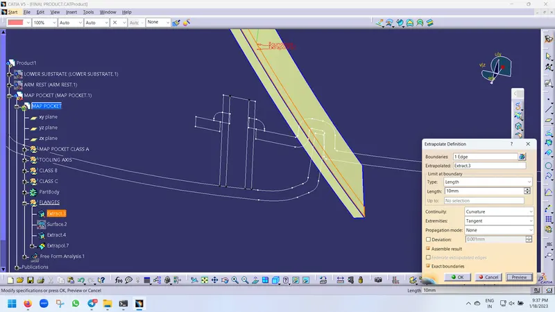
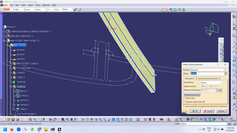
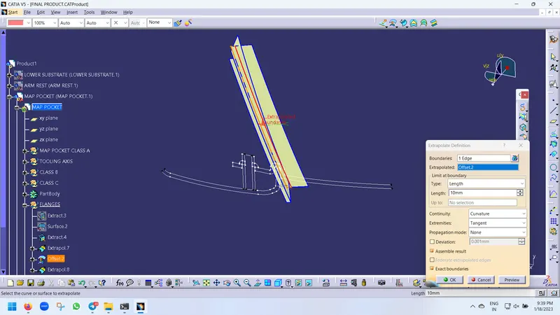
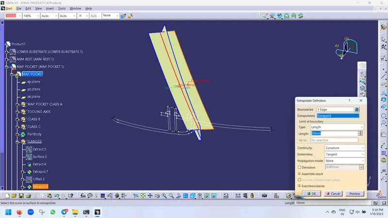
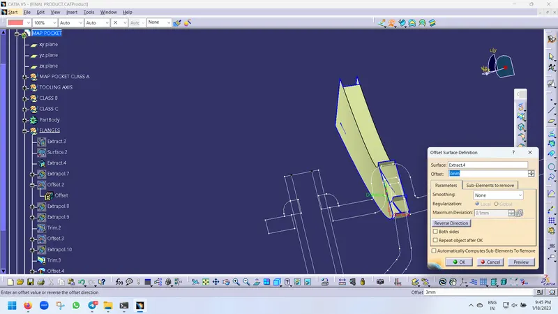
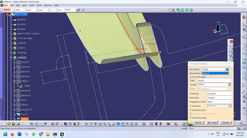
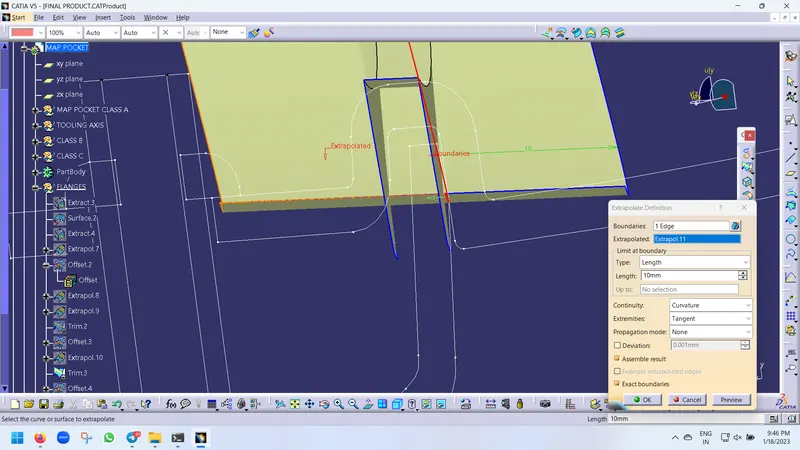
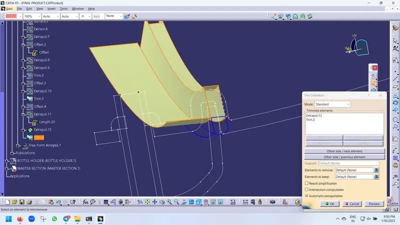
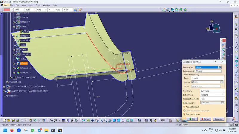
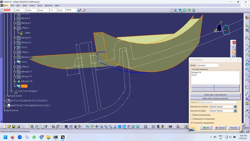
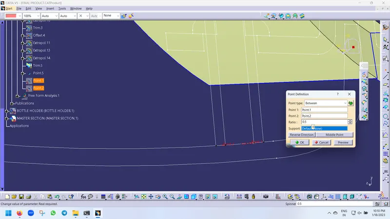
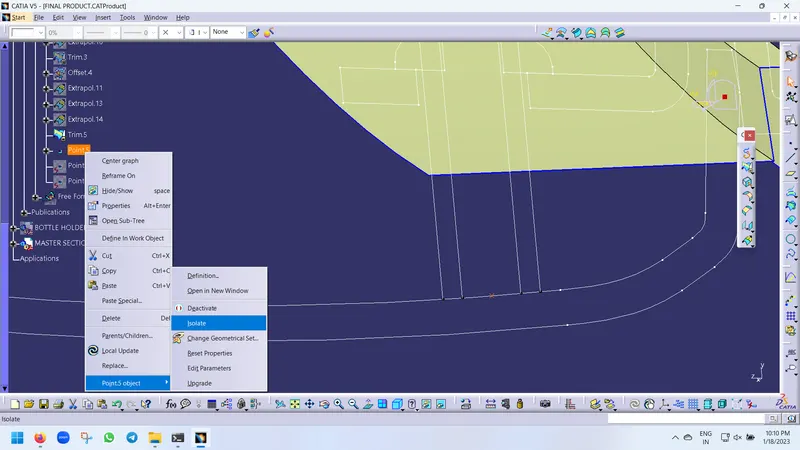
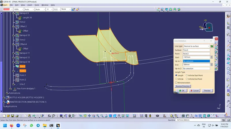
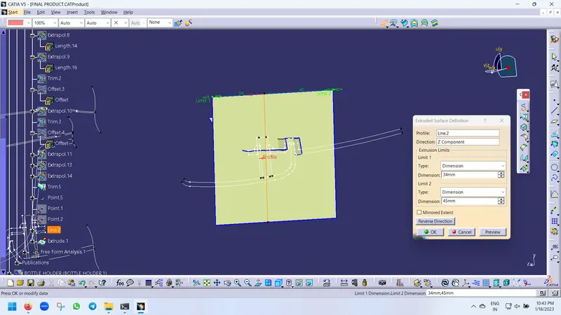
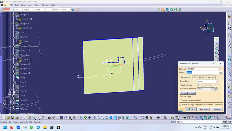
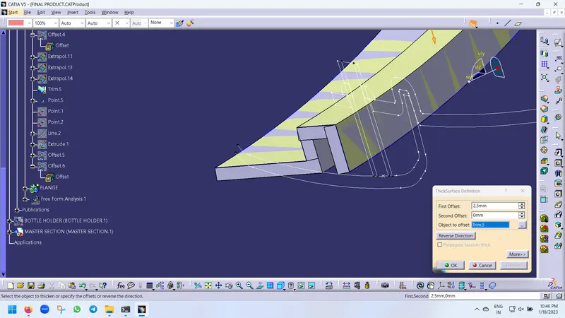
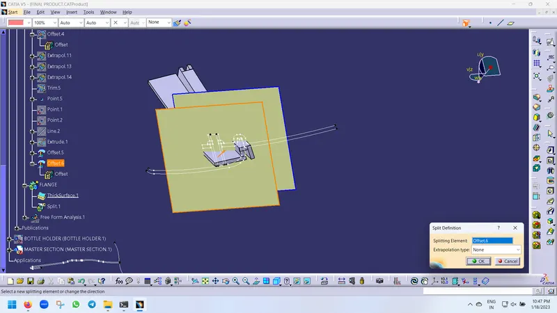
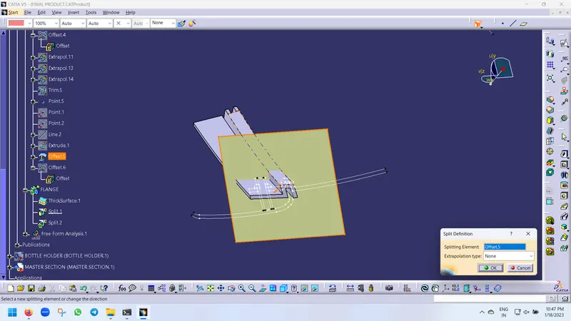
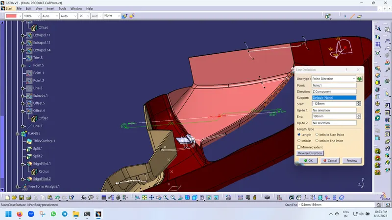
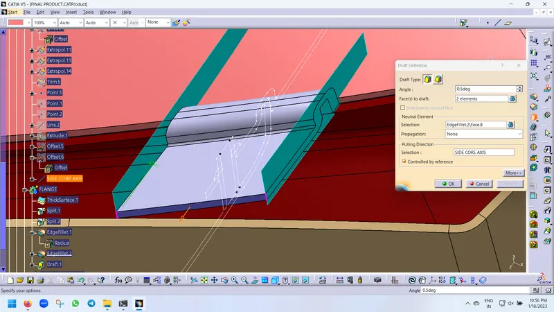
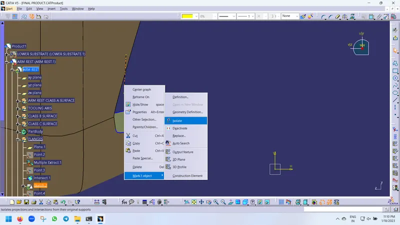
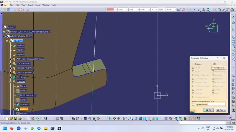
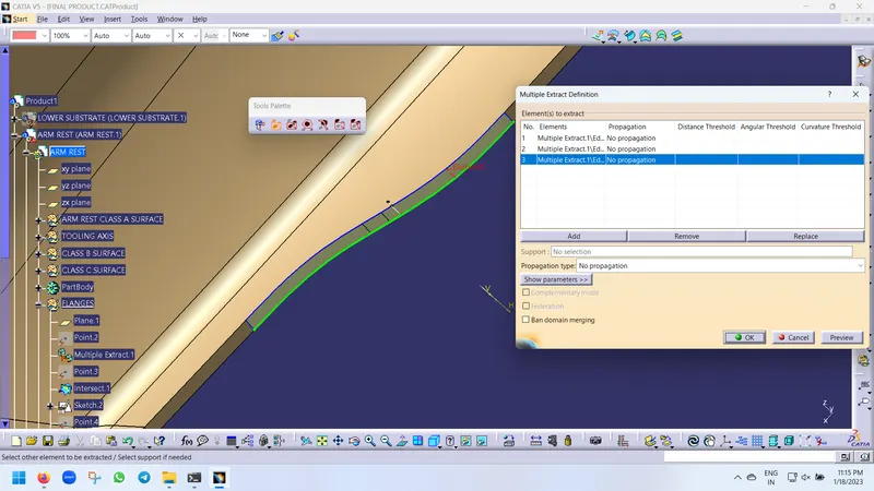
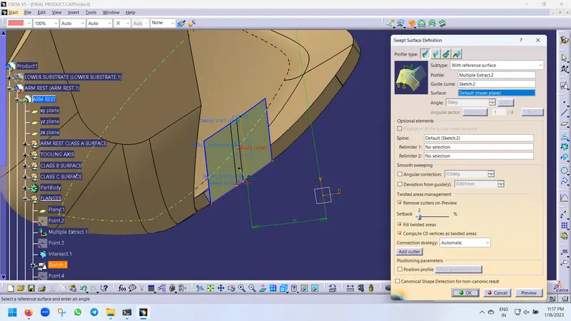
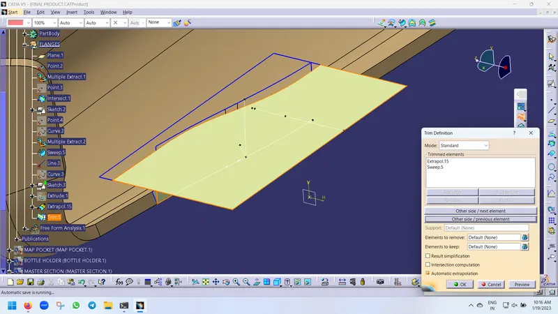
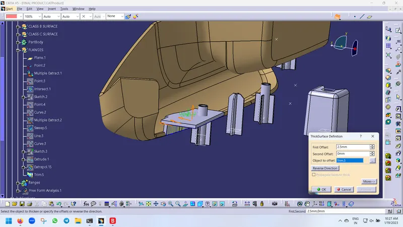
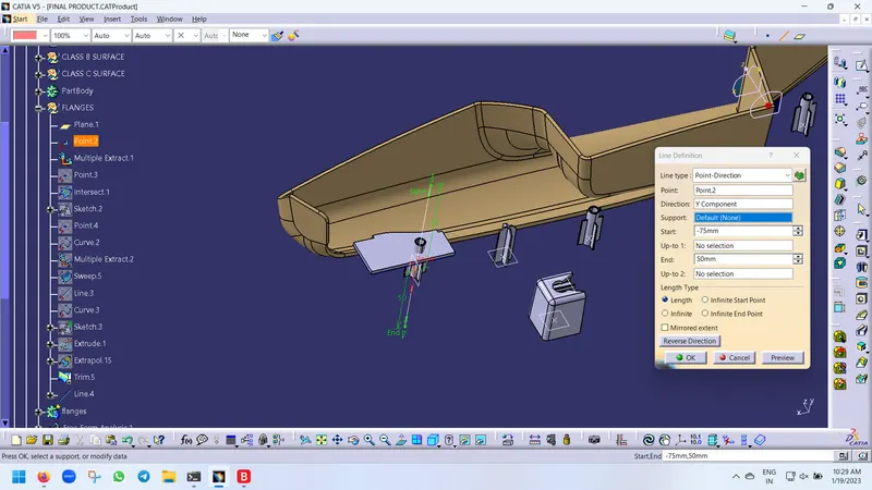
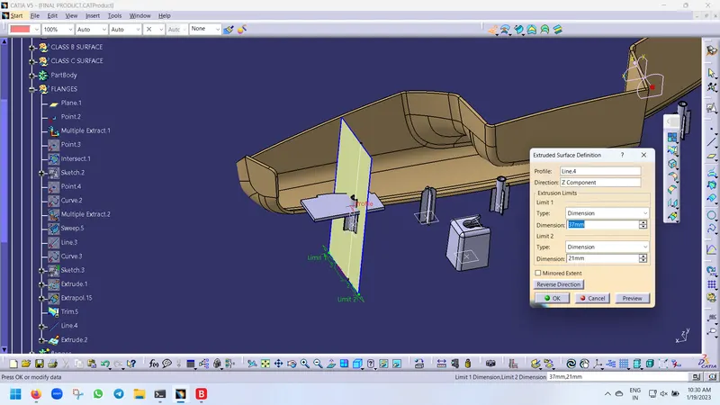
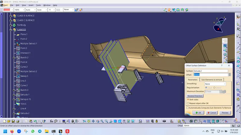
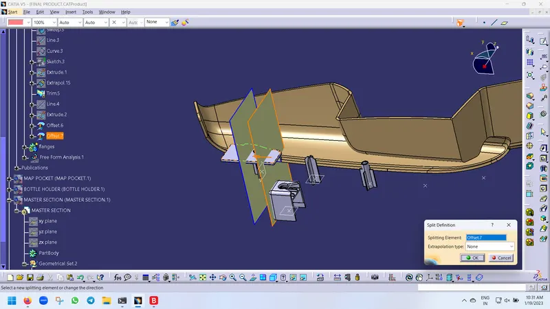
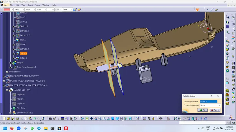
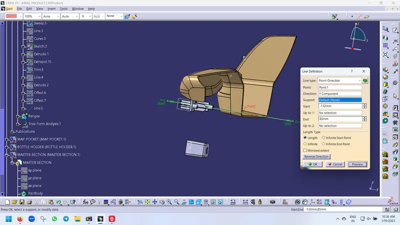
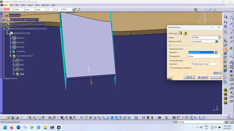
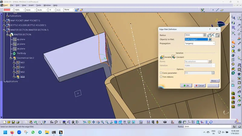
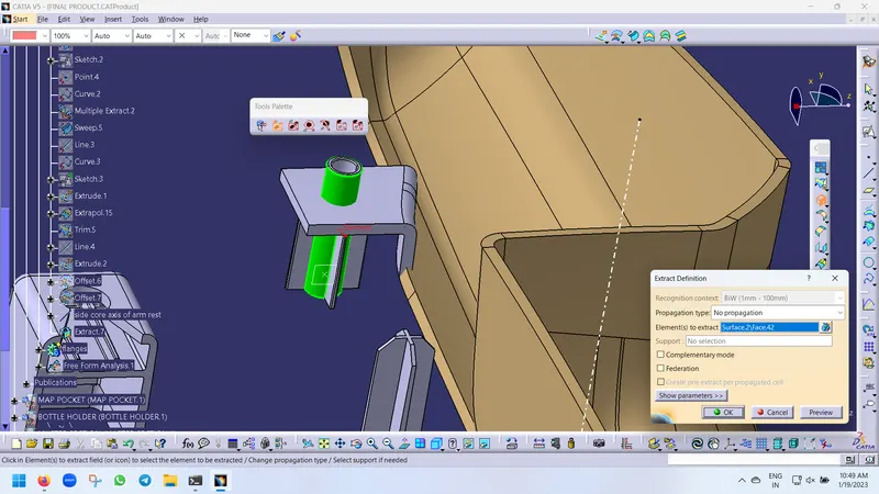
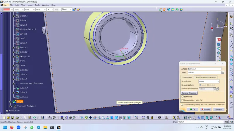
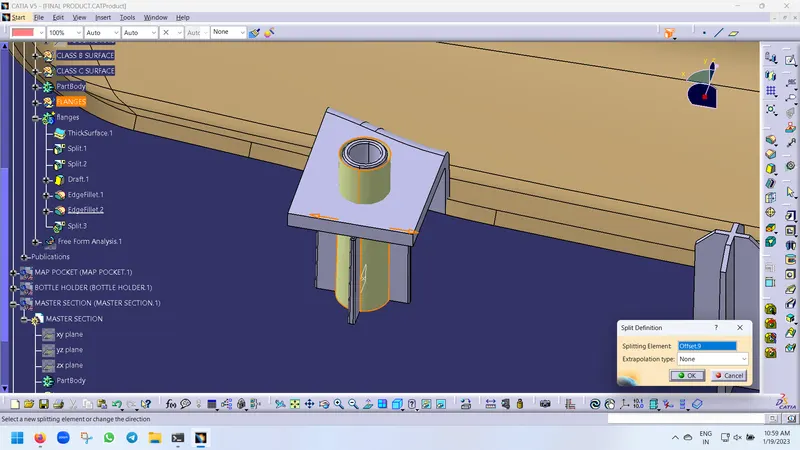
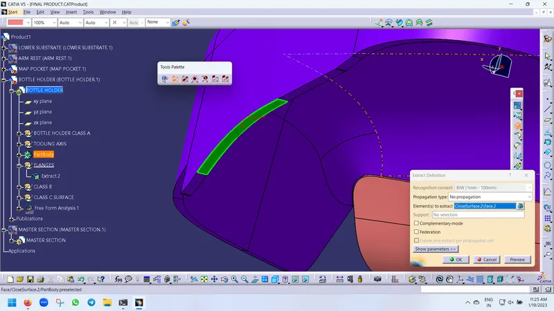
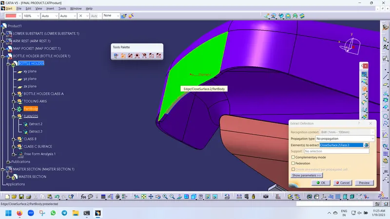
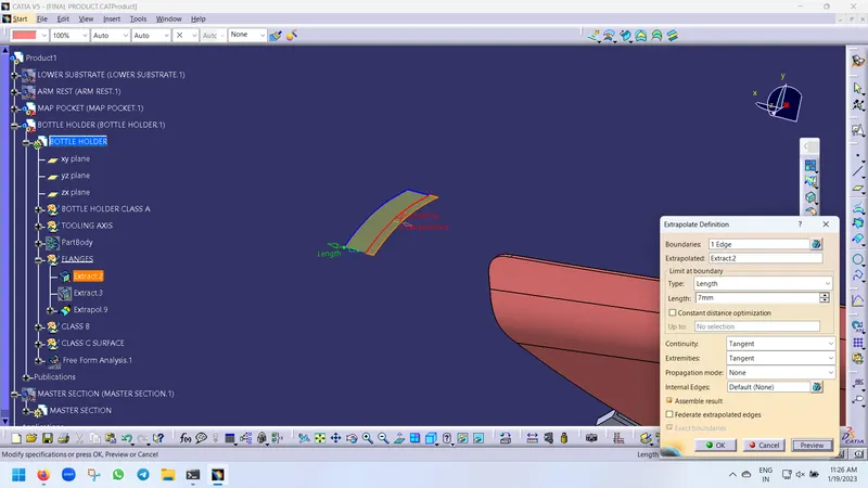
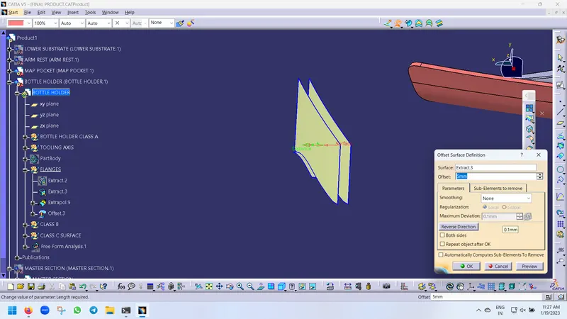
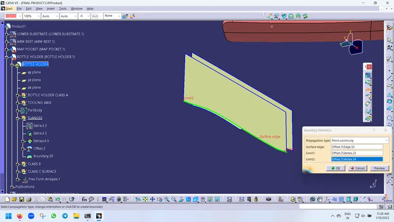
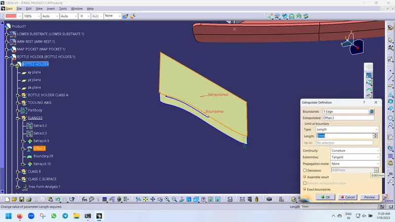
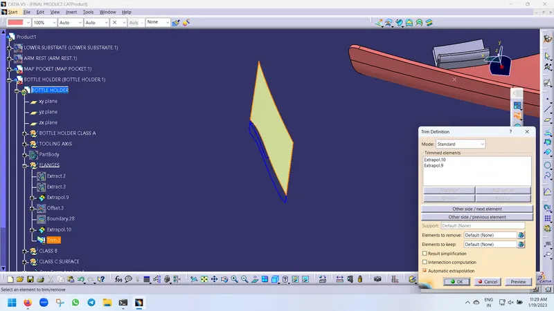
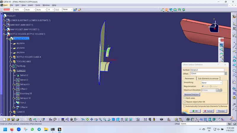
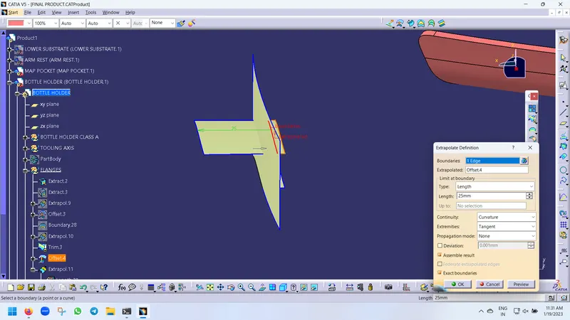
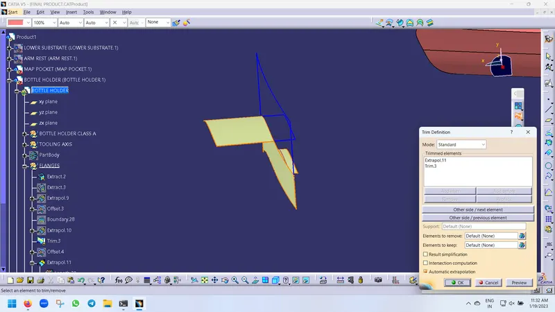
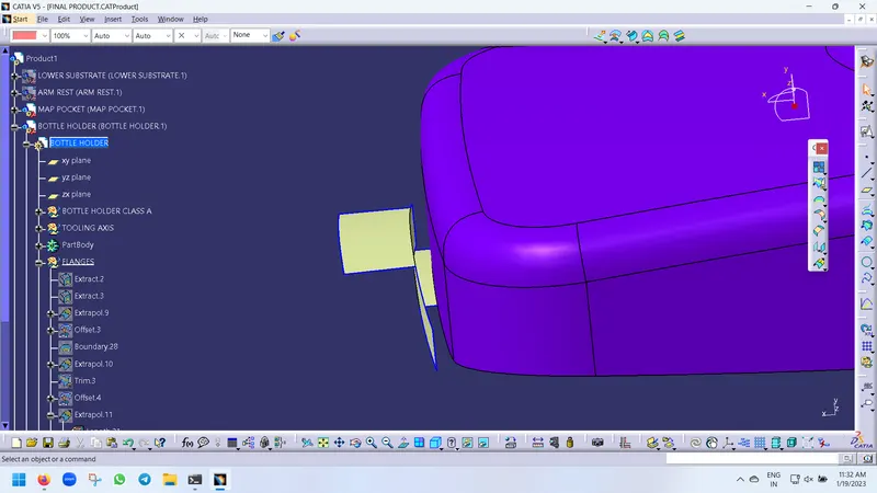
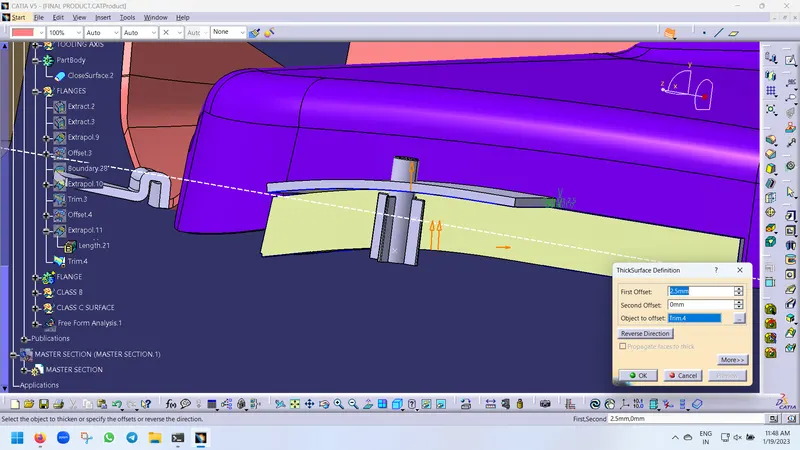
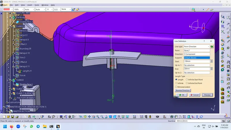
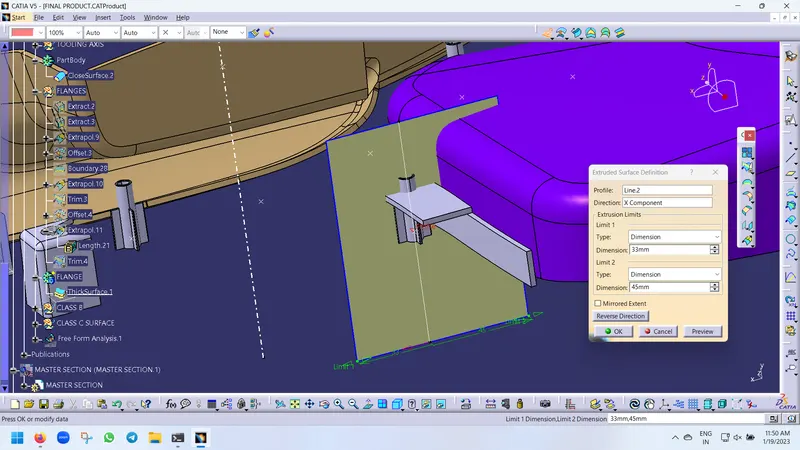
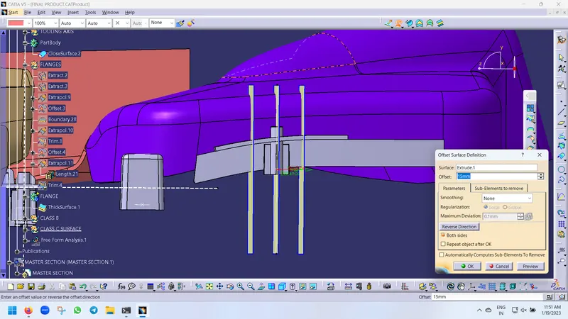
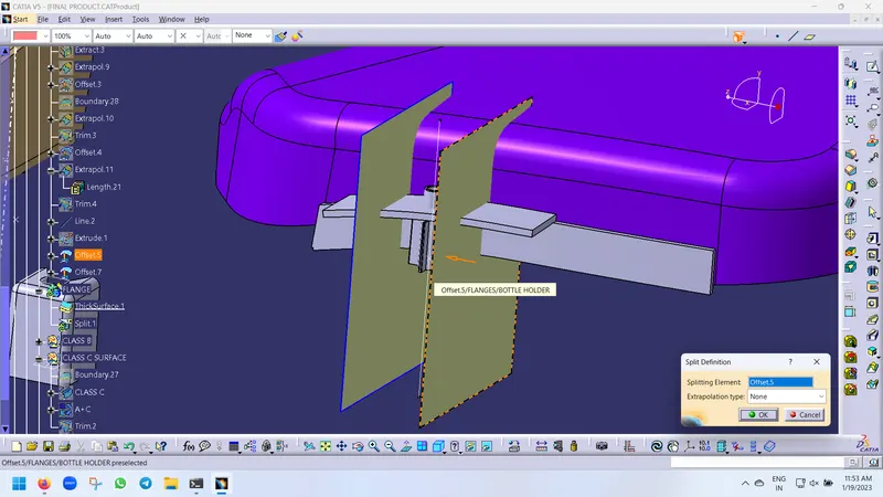
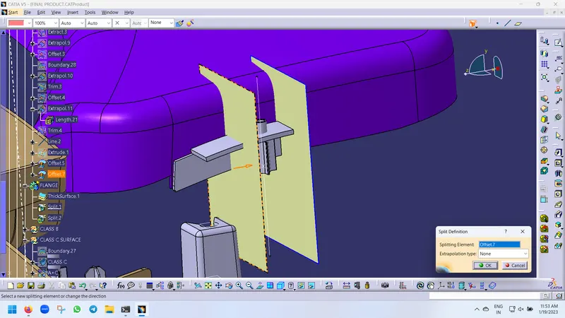
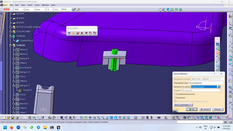
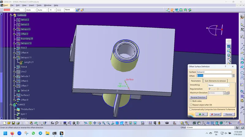
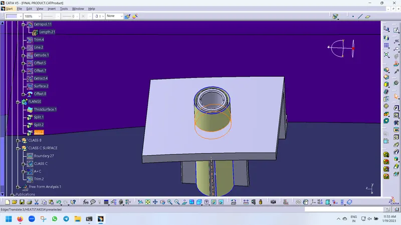
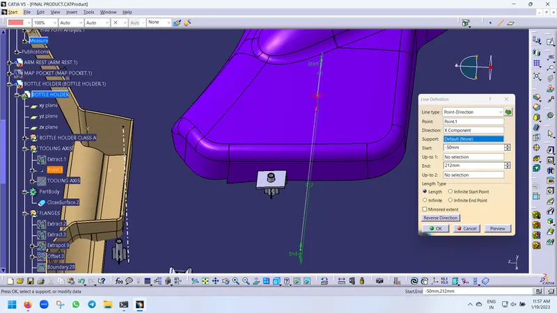
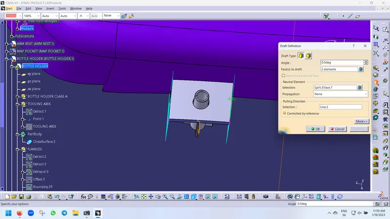
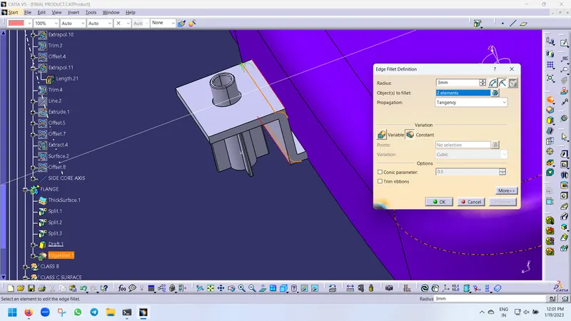
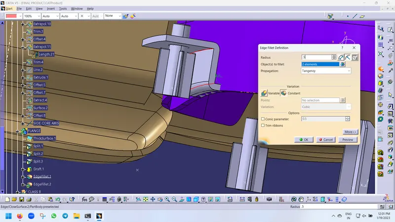
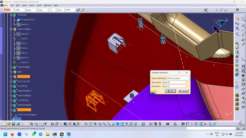
Fixing the Pushpin on the dog house:
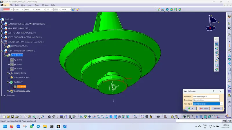
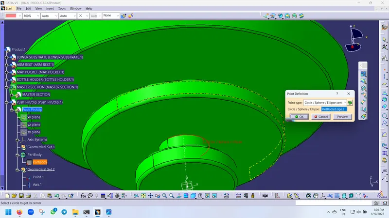
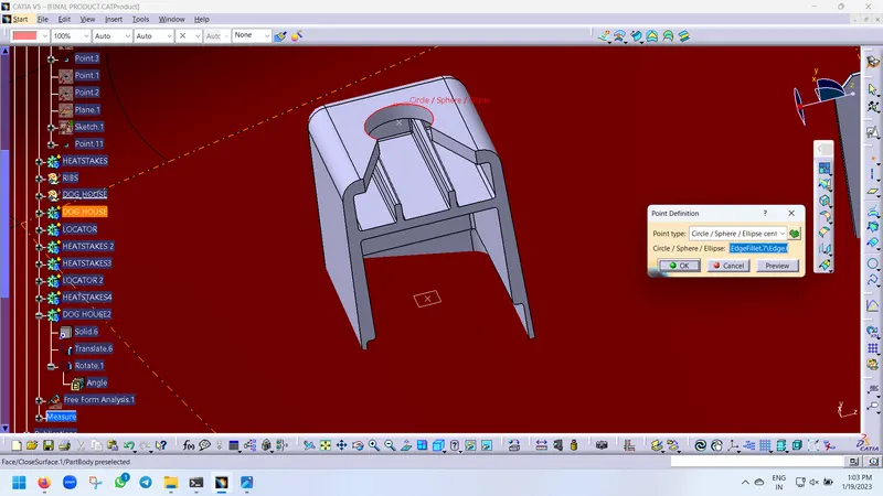

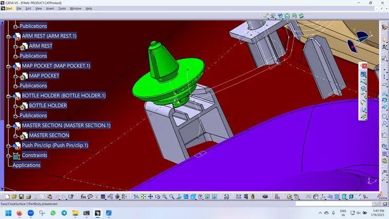
The final look of the design:
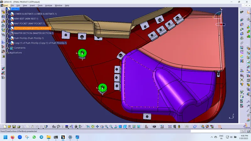
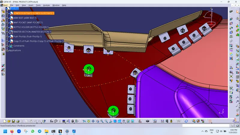
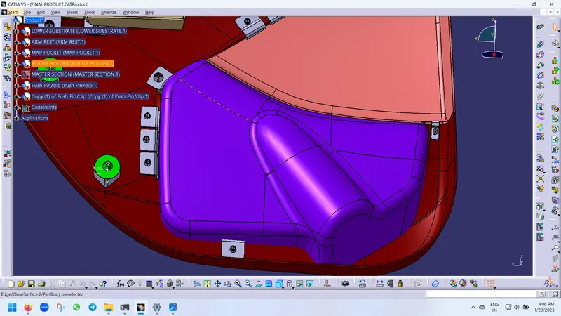
Final draft analysis of individual part bodies:
DETAILED REPORT:
Tooling axis creation
- The direction in which the mould opens and closes is called the tooling axis direction.
- Check the connectivity of the surface and ensure there will be no gap between the surfaces and then define the tooling axis.
- While creating a tooling axis please ensure to give the tooling axis on a flat-length surface.
- Create a point on the middle of the base surface by using a point on the surface command then create an intersection for the surface and extract the reference lines which will be helpful for creating the dummy tooling axis using the intersect method by creating a bisecting line.
- Use the line command and draw the lines aligned with the extracted lines and extend it to the required length.
Draft Analysis:
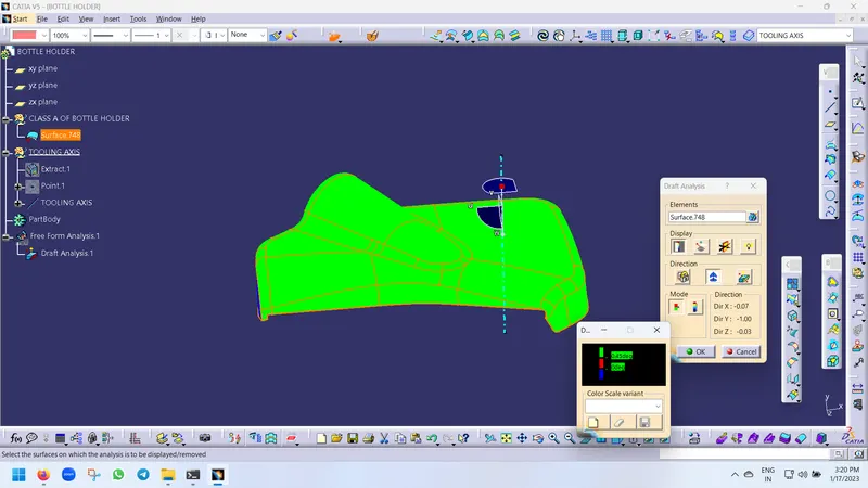
First, we analyze the model and then choose a dummy axis in the x and y direction.
As we intersected to proceed we observed that the side walls are not given any draft. Hence we assume the axis normal to the base surface and parallel to the side walls. This surely will create problems because a minimum draft has to be provided.
As the class-A surface is made by another designer only he is authorized to make changes, so we look over this to complete the coin holder for practice.
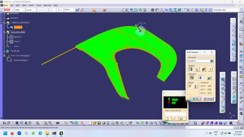
Now we go to insert< analysis< draft analysis and follow the usual procedure to do the analysis.
Align the compass and click on the surface and as expected the model is mostly in red color i.e. negative draft with respect to the axis.
To correct it as best as we can we moved the compass a bit till we got most of the surfaces in green and lock that position.
After hitting ok, we change the direction of the line from the z-axis to the compass direction. The axis will align itself accordingly.
NOTE: as the side wall does not have the draft, this result was expected and a few areas need correction. But still, we are moving forward to
complete the model
Bisecting method:
- Identify on which plane we have to do more operations and create the plane or axis on the component area and define it on the dummy tooling axis direction.
- Intersect the class A surface with that plane then we will get an intersection sketch. Look for the profile (inclined line) which will create a problem and extract it then extend it by using the line command.
- Then create a bisecting line with reference to the lines we have extended and this will be our main tooling axis.
- In this case, we have created a tooling axis along with the Y direction with reference to the base surface.
STEPS FOLLOWED:
- Stp file to product conversion
- Tooling axis creation
- Preparation of Class B & Class C surface
- Closed surface creation
- B-side features creation
Step 1 :
- The input is given as a step (.stp) file.
- Create an individual part
- Use save management to save all the parts
- Assemble the parts before working on B-side features.
Step 2 :
- The tooling axis is the direction in which the mold blocks move.
- Plastic features of all the parts will have the same tooling axis.
Step 3&4 :
- Create Class B & C surfaces for all the parts as usual.
- Bottom-up assembly can be used for closed surface creation.
Step 5 :
- After the closed surface, the engineering features should be created.
- While creating the engineering features, we should top-down assembly approach.
Engineering Features:
- Ribs
- Screw Boss
- Locators
- Heat Stakes
- Dog House
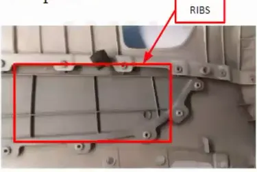
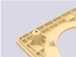
Ribs:
- Ribs provide a means to economical stiffness and strength in molded parts without increasing overall wall thickness.
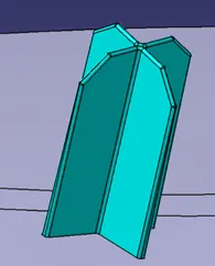
- They also facilitate Locating and arresting components of an assembly, Providing alignment in mating parts, and acting as stops or guides for mechanisms.
- Ribs are created on the non-appearing surface of the plastic part.
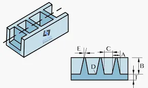
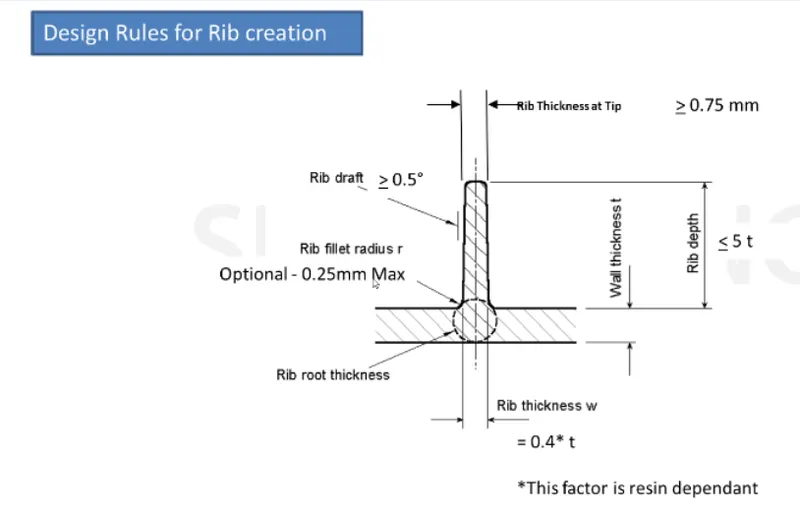
- T: Nominal wall thickness (3mm) ( a deviation of +- 30% from the wall thickness is accepted.
- A: Base width of a rib: 0.3 - 0.7T
- B: Rib height: less than 5T
- C: Spacing between ribs: more than 4T
- D: Radius at base of rib: T/8 or 0.25 mm max
- E: Draft of rib: 0.5 - 2 degree ( Ideal draft for a component is 3 degree but a Minimum of 0.5 degree is accepted in ribs.)
Screw Bosses:
- Bosses are used for the attachment and assembly of components
- They are cylindrical projections with holes to fasten the screw and threaded inserts.
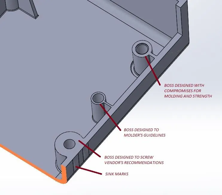
Design rules of Bosses:
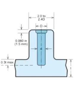
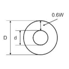
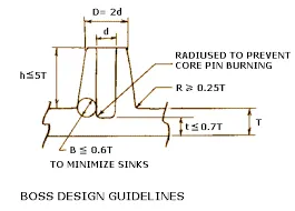
- The outer dia of the screw boss should be 2 to 2.4 times the outer dia of the screw.
Heat stakes:
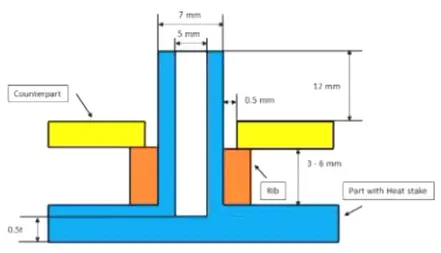
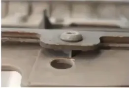
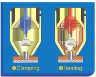
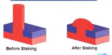
- Staking is an assembly process to join two or more components
- Can be used to assemble similar or different components
Process of staking - Thermal :
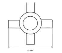
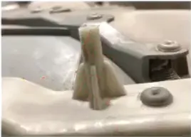
- The molded plastic part contains a projection (boss) which is melted and fills the volume of the forming tool cavity which in turn produces the head to lock the other part.
Dog House :
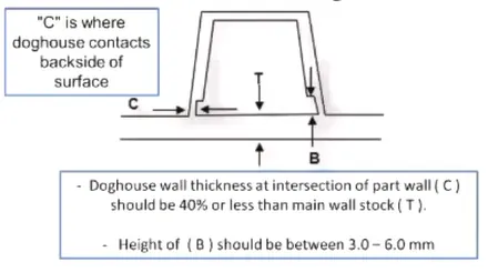
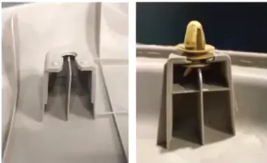
- The dog house is a supporting feature in the plastic trim
- Attachment features like bosses and locators are placed on them to increase the strength
Locators :
3-2-1 Principle
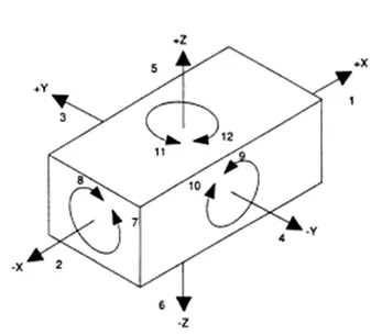
A workpiece free in space can move in an infinite number of directions. For analysis, this motion can be broken down into 12 directional movements or "degrees of freedom". All 12 degrees of freedom must be restricted to ensure proper referencing of a workpiece.
As shown in Fig 1, the 12 degrees of freedom all relate to the central axis of the workpiece. Notice the 6 axial degrees and 6 radial degrees of freedom. The axial degrees of freedom permit straight-line movement in both directions along the 3-principle axis shown as X, Y & Z. The radial degrees of freedom permit rotational movement, in both clockwise & counterclockwise radial directions around the same three axes.
Degrees of Freedom of a Rigid Body
Consider the rigid body shown below which is situated in space. It can have 12 degrees of freedom.
2-WAY LOCATORS:
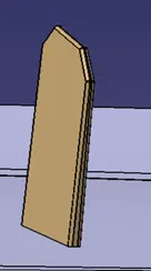
A 2-way locating pin restricts motion along 1 axis (or 2 degrees of Freedom), like a round pin in a slot. Likewise, a 4-way pin restricts 4 degrees of freedom along 2 axes. A round locating pin located concentrically in a hole is a common application of a 4-way pin, and helps to further secure the piece.
4-WAY LOCATORS:
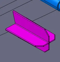
4-way mean you prevent movement at 2 axes (+X, -X, +Y and -Y) on the plane. Generally, you have a cylindrical pin on the fixture and a circular hole at the workpiece part.
Conclusion:
Creation of the car interior door trim is designed using the given class A surface as the input and Class B and C surfaces are created with the help of the Class A surface. By using the given master section attachment features I.e. Heat stakes, Flanges, Dog houses, and Push Clips are created using the design rules. The draft analysis has been performed to analyze the draft of the component to manufacture easily applying draft to the surface by 3 degrees and 0.5 degrees to the attachment features. With all data and reports, we can conclude that draft analysis is very important to design any plastic component to mold the plastic easily. The analysis will verify that all surfaces are favorable for being pulled from a cavity. It may also highlight or give insight into defect areas.