Week 11 - Final project
DEVELOPMENT OF A DOOR TRIM PANEL
AIM;
To design and development of vehicle interior door trim using Catia V5 with given class A surface along with Master section. Also create the Side Attachment features as per design.
OBJECTIVES;
To create thickened part using master section for reference and create the mounting features as per design guidelines in the industry and with master sections check Draft analysis & Tooling analysis
COUNSTRUCTION;
CREATION OF CLASS A,B AND C SURFACES
Creating the B-SURFACE by extracting the class A surface, by each surfaces separately, it is offset to certain distance, making point on the master section to get the intersection
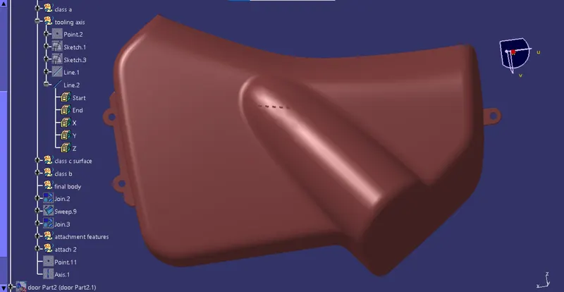
Extracting the boundary of Class A surface and it is make into smooth curves to sweep the curves by using support surface to the 90 degree respectively.
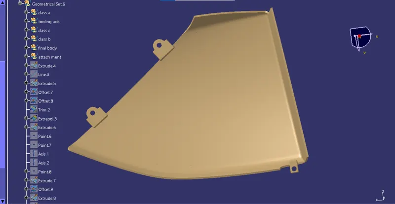
Once the all surface joined together it extrapolated to certain distance to trim with A Class surface to C surface. Finally we created Class C surface.
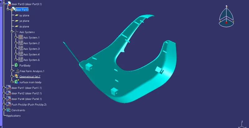
To make the final component the Class C surface is trimmed with Class B surface, the output will get the component with 2.5 mm thickness of surface and it is converted into solid body using insert body option in part design
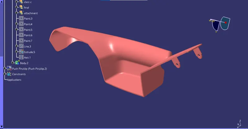
CREATING ATTACHMENT FEATURES
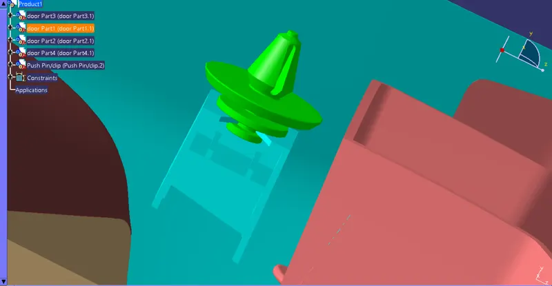
Dog house is an engineering feature used in plastic trim design. Dog houses are used as supporting feature. Sometimes other engineering features like snaps; locators etc. are mounded on them to increase their strength. Dog houses are subjected to draft analysis to prevent breakage of the component during ejection from mould cavity. Dog house and other engineering components are built on B-surface
Creating the sketch by extracting the class A surface, by each surfaces separately, point and axis system created simultaneously on the surface.
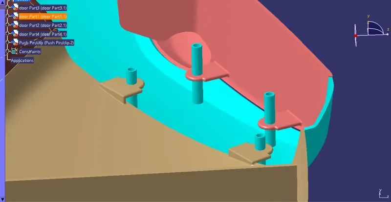
Heat staking is a pulsed – heat process to join two or more parts out of which one at least is made of plastic . The plastic is to deform the plastic material using the heat and foam at a set process time. The bond is made by partially de forming the plastic part in order to fix the other. Heat stakes makes it easily to bond metal to plastic is commonly used in high volume and low cost application such as Automotive, IT and consumer appliances
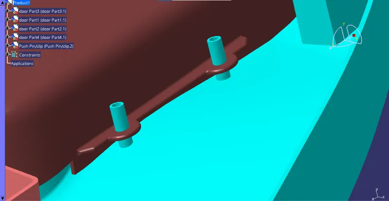
Creating the sketch by extracting the class A surface, by each surfaces separately, point and axis system created simultaneously on the surface. Using positioned sketch.
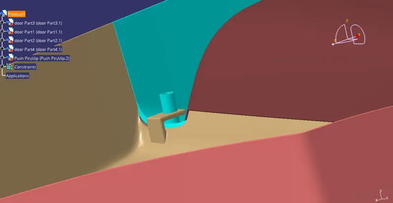
The sketch feature is then extracted to the required dimension. And it is drafted for the 0.5 deg to the sliding tooling axis, it is filleted for radius 0.25 of smooth edges
CREATING TOOLING AXIS AND DRAFT ANALAYSIS;
The tooling direction is used to find the direction in which the part is removed from the core and cavity. The draft angle should be positive to the tooling axis to manufacture the component easily. The step by step procedure of creating the tooling axis .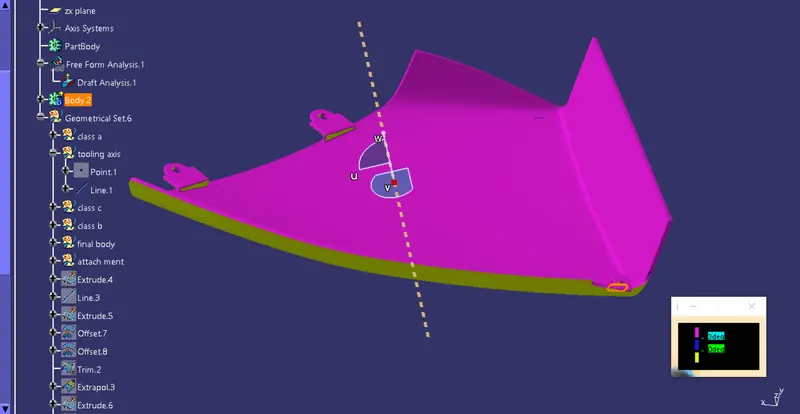
Creating the tooling axis for Map Pocket by create a point on surfaces respectively to the 0 value. It automatically create at mid surface and generate the line to the direction of y axis.
Once compass is locked in the axis, directly click on the surface it will appear quality of draft surface whether, it is pass or failed. Here the draft angle is given as 3 degree. Hence we achieved green colour on top surface. Hence it accepts the draft angle for the surface, so we build good quality component
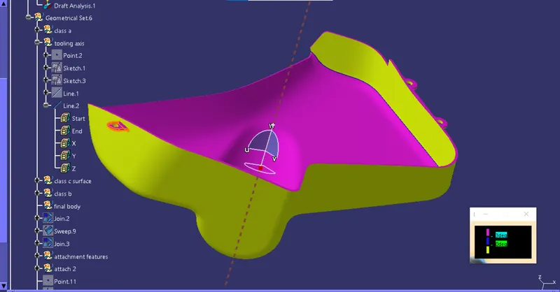
Creating the tooling axis for Lower Map Pocket by create a point on surfaces respectively to the 0 value. It automatically create at mid surface and generate the line to the direction of y axis.
Initially we perform the draft analysis to the class a surface to ensure that we have good quality of surface to make Class B and C surface to achieve the same kind of quality surface. First we have to set the compass on the main tooling axis to get the direction of core and part moves along
CREAT SIDE CORE TOOLING AXIS FOR ATTACMENTS;
For Attachment Features the draft angle is applied for 0.5 deg and its analyzed using the sliding tooling axis
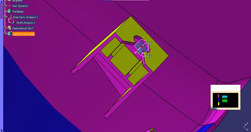
First we have to set the compass on the main tooling axis to get the direction of core and part moves along as shown below.
Here the draft angle is given as 3 degree. Hence we achieved green colour on top surface. Hence it accepts the draft angle for the surface, so we build good quality component.
Now we check colour variant scale to ensure the maximum and minimum area draft angle is achieved by displaying by green, red and blue colour respectively. If the surface appears red in colour while analysing it is not accepted.
We can check the angle of draft given to surface by using draft tool analysis just point the over the surface where we have check angle of given draft to the component as shown below.
PRODUCT ASSEMBLEY;
All counstructed part move to product assembly and its connect with attachment features of parts and check output of final product
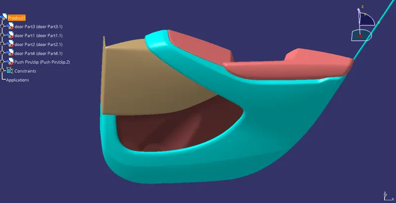
create a coincidence constraint between two components of the active component
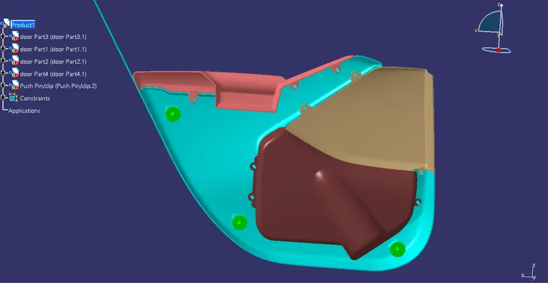
Fix the component position in the active component.
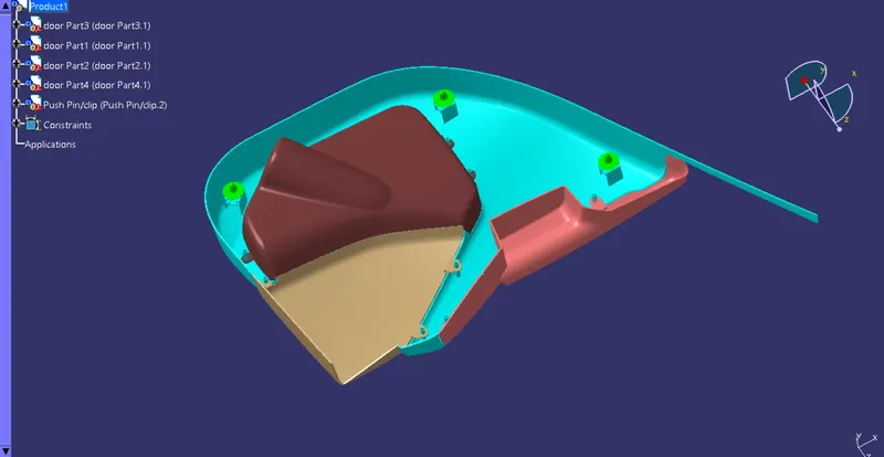
Use heat stakes for part to part attachment.FINAL PROJECT OUTPUT