Development of Door Trim Panel
Development of Door Trim Panel
Automotive Plastic Trim:
The design of Automotive Interior and Exterior plastic components is called Trims. The plastic components that you see inside the car are Interior. Ex: Dashboard, Instrument Panel, Doors, seating, and pillars. Plastic components that you see outside of a car are Exterior. ex: bumper, light assembly, hoods.
Door Trim:
The door panel covers internal parts like the window regulator, the power window motor, and the wiring. It is attached to the sheet metal part of the door. It is designed differently based on the design of the sheet metal part of the door. Besides its aesthetic look, it also has many functional features attached to it such as an armrest, bottle holder, speaker attachment, etc. In older cars, door panels used to be made out of cardboard and upholstered with material that matches the rest of the upholstery within the cabin. On the other hand, most modern cars have door panels made from plastic. The main materials used include kenaf, which grows year-round and has excellent CO2 absorbing properties, and plant-derived plastic, making them environmentally friendly as well.
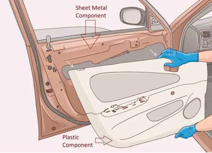
Fig:1
Aim
To design and development of vehicle interior door trim using Catia v5 Tool using give A Class Surface and Adding thickness to it. In order to fix the parts and to provide stiffness create Ribs, Locators, Heat stakes as per the given Master section
Model
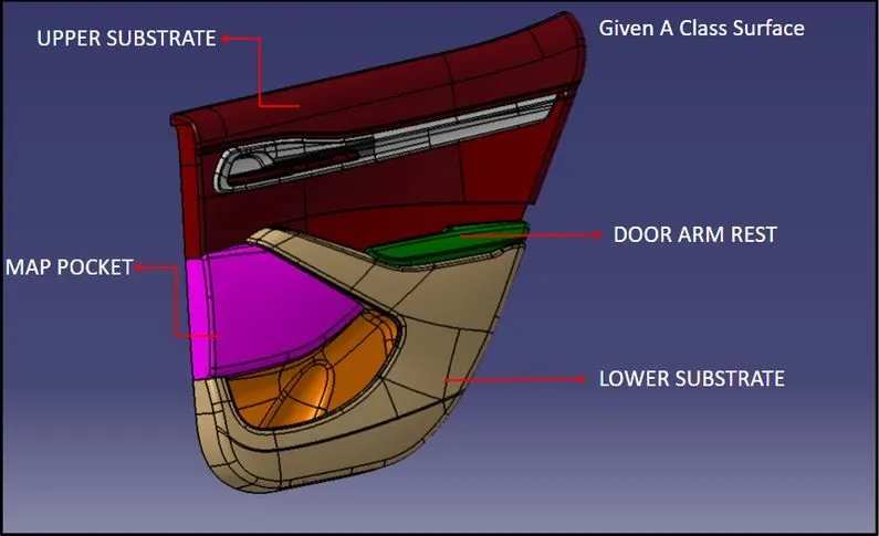
Fig:2
Procedure
1. Import the file: File > open > browse file and select the given file
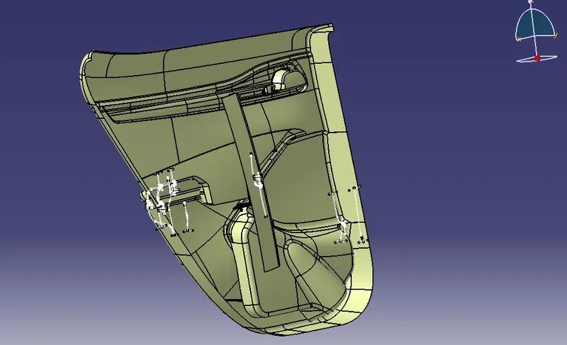
Fig:3
2. Creation of tooling axis: Tooling axis is nothing but the direction in which the Core and Cavity Opens and Closes. Design Engineer works is to Analyse the Class A Surface and find out the best possible tooling direction keeping in mind all the draft angle is with respect to the tooling axis so that the Component can be easily ejected from the moulds.
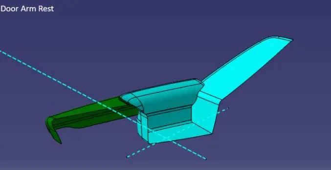
Fig:4
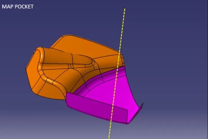
Fig:5
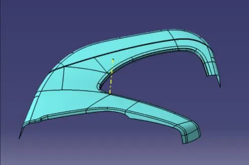
Fig:6
3. Draft Analysis: Parts Cannot be ejected from the tool if it is at 90-degree surface. For this reason, a small Draft angle is to be provide for each and every surface’s of the Component in order to easy removal of component from the moulds without any defects. Draft is the angle in which the part is tapered to allow it to release. Most of the part require minimum 1/2 degree to 1 degree however 3 degrees are widely used and accepted in plastic component design. Draft Analysis is the technique used to analyse whether our designed product are manufacturable with required conditions or not.
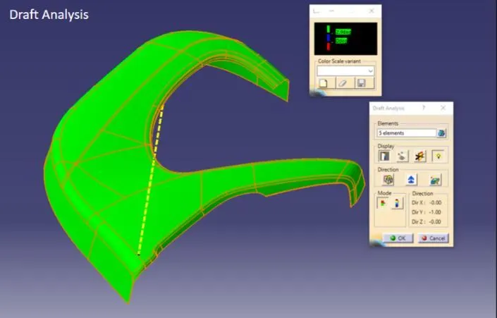
Fig:7
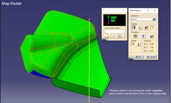
Fig:8
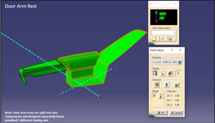
Fig:9
4. Master Section development: As per the given class A surface, master section is given inorder to create the flange for the fixation. So in the given class A surface flanges need to created.
5. Class B surface creation : For all parts Class B surface is created by direct offfset and extrapolated.
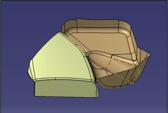
Fig:10 (Map pocket)
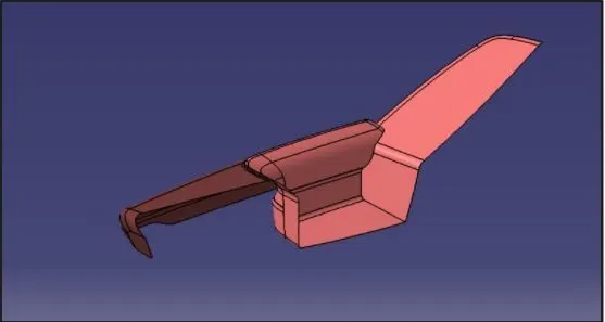
Fig:11 (Arm Rest)
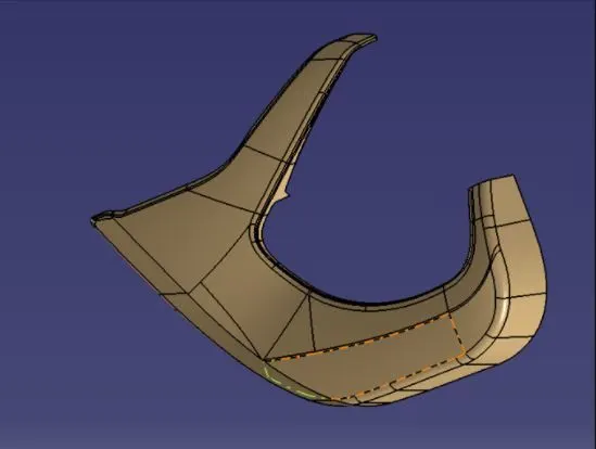
Fig:11 (Lower substrate)
6. Class C surface creation: Class C Surface is swept along the boundary of the Class A at an angle perpendicular to the CLASS A surface with respect to the tooling axis direction with a draft angle of 3 degree.
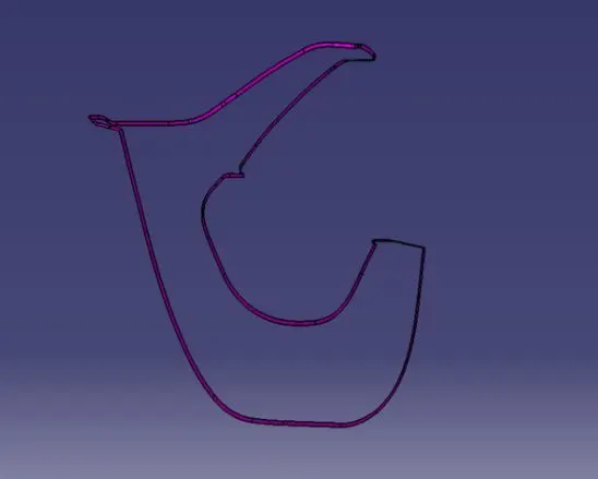
Fig:12
7. Joining Class A,B and C: After finishing all the 3 surfaces, join the class A and class C surface together using the Join command. Now, the joined surfaces are then trimmed with class B surface to form a closed surface. After that use closed surface option to make the component to be solid
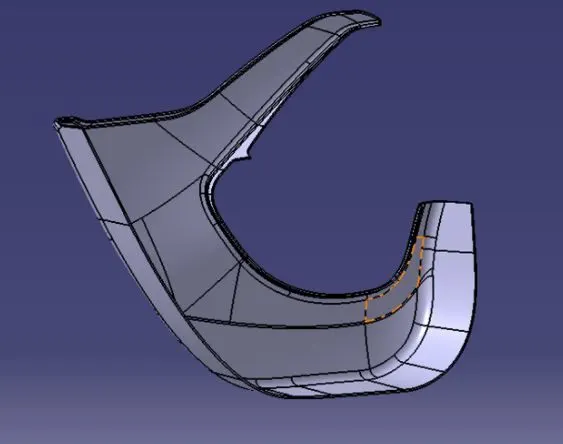
Fig:13 (Lower Substrate)
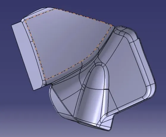
Fig:14 (Map Pocket)
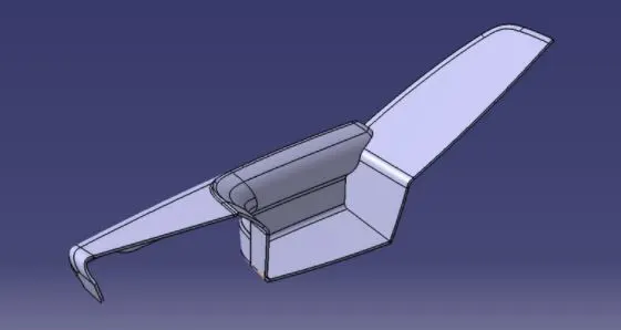
Fig:15 (Arm Rest)
8. Creation of Ribs: Create the ribs as per the design rules and give the required draft angle. Ribs are created to increase the stiffness and strength of the surface.
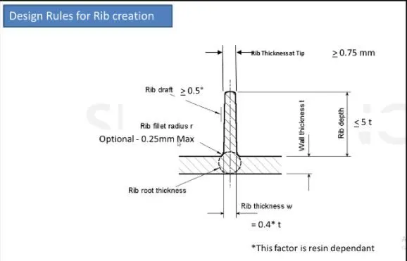
Fig:16
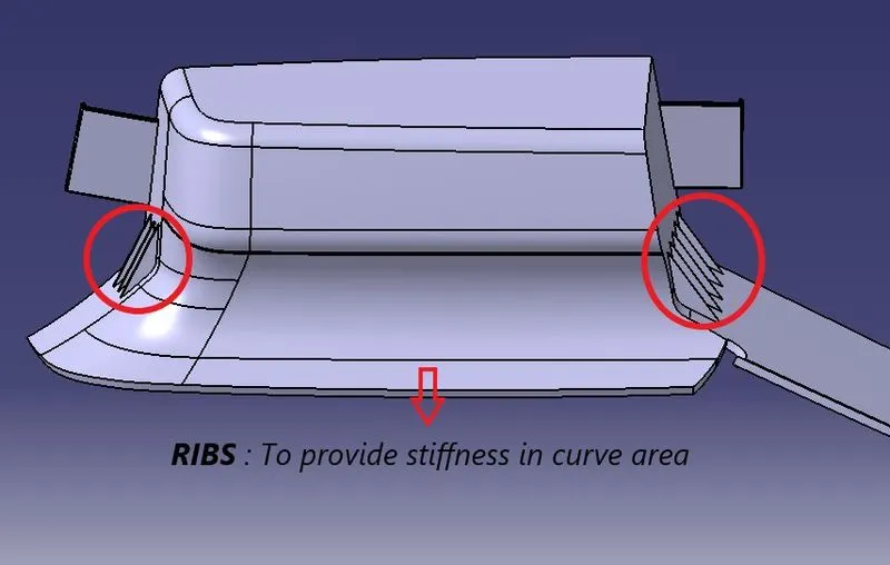
Fig:17
9. Creation of Dog house
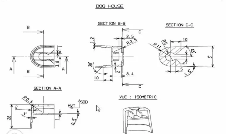
Fig:18
- Doghouse wall thickness at the intersection of the part wall ( C ) should be 40% or less than the main wall stock ( T ).
- Height of should be between 3.0 – 6.0 mm
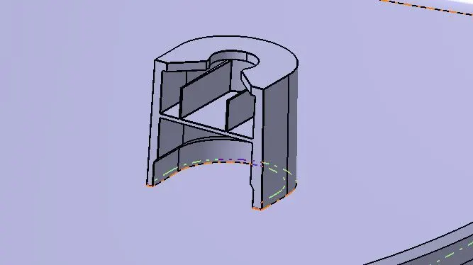
Fig:19
10. Creation of Heat stakes: Heat Staking is a pulsed-heat process to join two or more parts out of which one at least is made of plastic. The process is to deform the plastic material using heat and force at a set process time. The bond is made by partially de-forming the plastic part in order to fix the other.
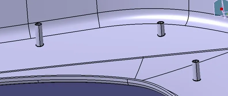
Fig:20
11. Creation of Push clips
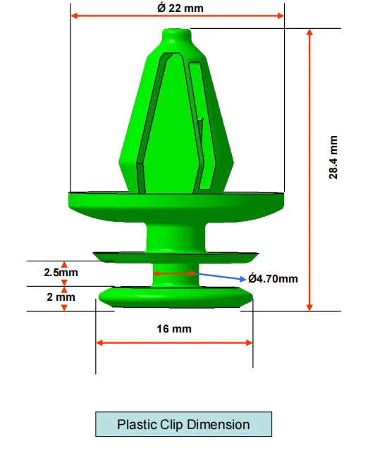
Fig:21
12. Draft analysis for finished component
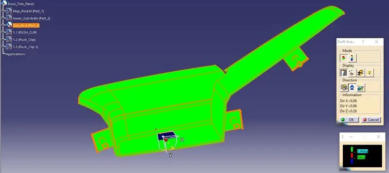
Fig:22 (Draft analysis for Arm rest part 1)
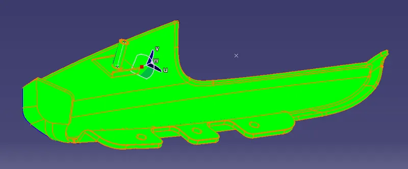
Fig:23 (Draft analysis for Arm rest part 2)
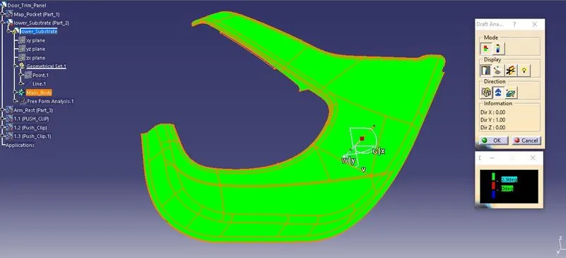
Fig:24 (Draft analysis for Lower substrate)
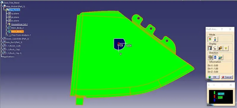
Fig:25 (Draft analysis for Map pocket part 1)
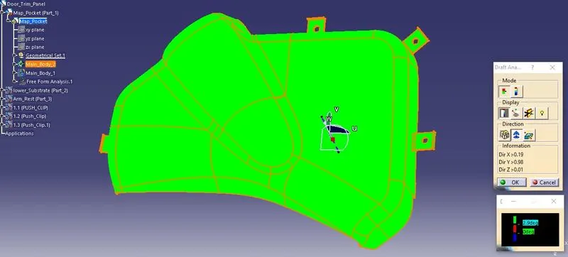
Fig:26 (Draft analysis for Map pocket part 2)
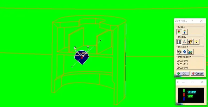
Fig:27 (Draft analysis for Dog house in side core tooling axis)
Final Model
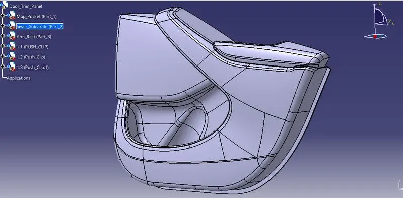
Fig:28
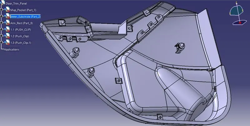
Fig:29
Conclusion
The Interior trim of the Car interior door trim is designed using the given A Class Surface as the Input and B and C Class Surfaces are created with respect to the A Class Surface. By using the given Master section attachment features i.e., Ribs and doghouse, flanges and push clips created considering all the design rules for creation of Ribs and Doghouse. Also carried out the draft analysis to check whether the Component is easily manufacturable or not with the given draft of 3 degrees for the surfaces and 0.5 degrees for the attachment features. With all these data’s and report we can conclude that the Draft Analysis is Very important to design any Plastic Component because when we making a part that will be moulded, the analysis will verify that all surfaces are favourable for being pulled from a cavity. It may also highlight or give insight to "trouble" areas.