Week 11 - Final project
The project I did is of development of door trim from the given class A surfaces inputs.
Models created are:
- Lower substrate
- Map pocket
- Arm rest
For creating of CAD models the following inputs are taken under consideration of following inputs as like in OEM and tier1 companies
- a) Class A surface
- b) Nominal thickness : Refered from master sections
- c) Attachment strategy
Then the given input is downloded and opened in catia v5 as we used catia for plastic component design learning.
The below shown is the input gotten.
The total surfaces given was:
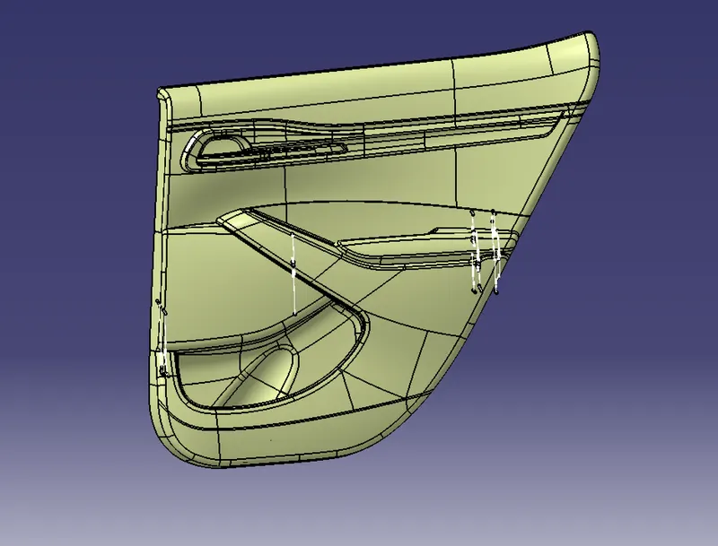
The given master section :
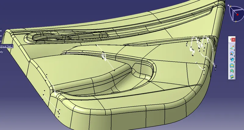
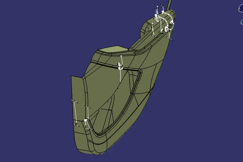
The surfaces took to convert into class A surfaces and used to create 3d CAD model:
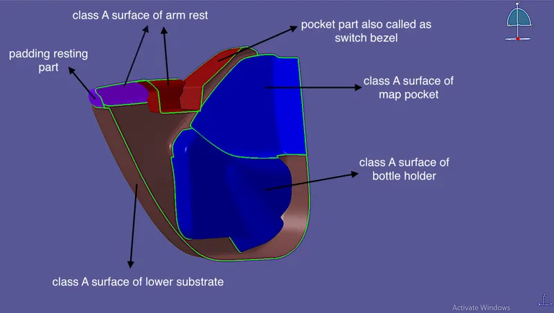
As the arm rest and the map pocket are a little bit like complex plastic component they was seperated into two parts each with considering the tooling axis. As like I divided it as arm rest into pad resting part and the pocketed side as pocket part or switch bezel. So now these surfaces was orderly selected and joined, so that it would create the expected class A surface like shown below:
After joining and creating the class A surface it was proccessed to draft analysis to check whether the tooling axis created is able to clear the class A surfaces.
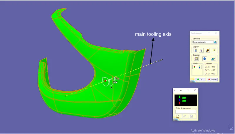
As class A of the lower substrate appears in green colour this represents a positive value of draft when the angle is equal or greater than the nominal draft angle.
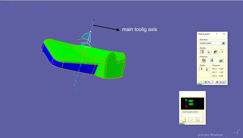
In this class A of the bottle holder maximum appears to be in green colour but there are some blue patches, which is not a positive draft angle but also not a negative draft angle. This represents the value which is lesser than the nominal required angle but also not less than 0. Its ok to have some blue patches.
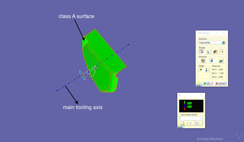
Then the class A of the map pocket is analysed and found to have green in all which represents a cleared draft values.
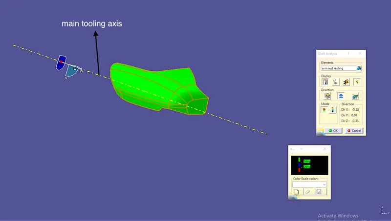
The class A of the pad resting part of the arm rest is also cleared as it shows green in all.
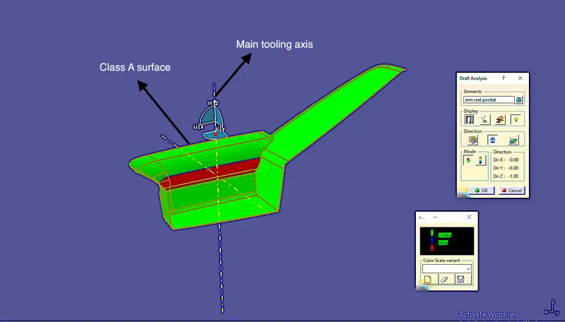
Then when comes to the class A of the switch bezel all sides are cleared except one surface. Which shows red colour ad that indigates a negative draft angle value.
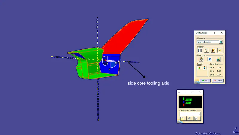
So to clear that surface a side core is used to clear and create that buldge. This is an other reason to split the arm rest part into two parts.
After finishing the draft analysis the CAD model is started to create. We made the solid part of all the part given first then the B side attachment features was created then. So that it would be a little bit easy to create.
So First I took the lower substrate and solided it with the nominal thickness of 2.5mm which was took from the master section which is given as reference.
In this the close surface modelling was used, so to create the B surface the class A surface can be offsetted, but as software deffers it gives some different errors to different type of models. In this the offset was not creating fully as it has some least fillet values which vanishes or becomes sharp edge when offsetted. So the offset was created with some empty patch spaces. There is an other way also to create the B surface which is by extracting the flat not filletted surfaces from the class A surface and trimming it after extrapolatig the untrimed stage of the extracts. But I choose the offset method and created the surfaces which was emptly left by using multisection and sweep commands even fill command was also used in some places when required.
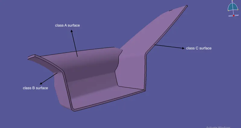
Like wise the C surface was created. This C surface is the surface which connects the A surface and the B surfase and form a closed surface.
As these are plastic components they will be created by injection molding method. In injection molding ther will be core and cavity mold which closes to create them solid.
The line which seperates the core and cavity is called as parting line. In which the extra bur may be created.
So this is also took under consideration of when creating the C surface, cause the parting line should not be lying on the class A surface as it is the one which projects outside to the customers where as the B surface and the C surface hids inside. So it wont be a prblem if the parting line lies on the B surface or the C surface.
So the C surface was created in a way of angle in which this surface clears in draft angle analysis and the pating lie lies on the this surface.
And after creating the C surface I extrapolated the B surface. So the C surface and the B surface passes through eachother. So it can be trimmed together and can be come as a closed surface. And it was solided.
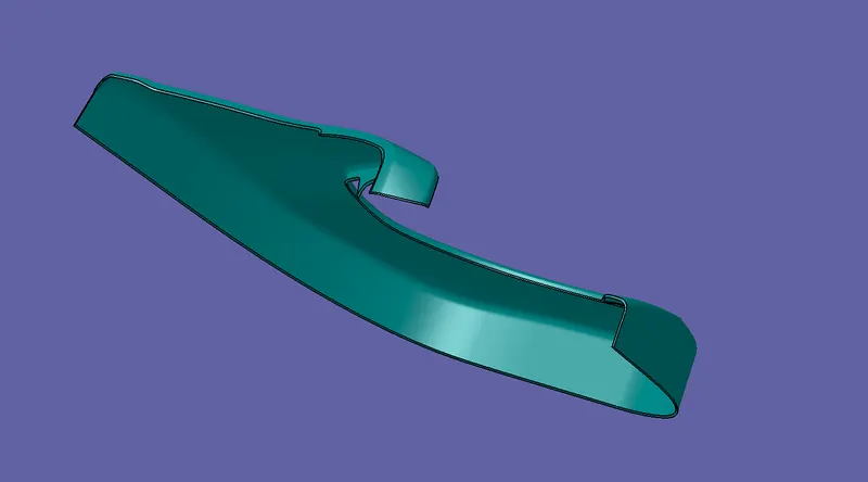
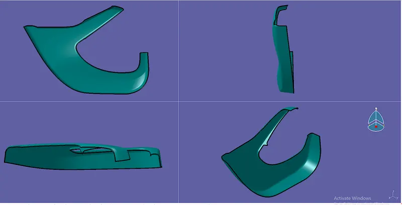
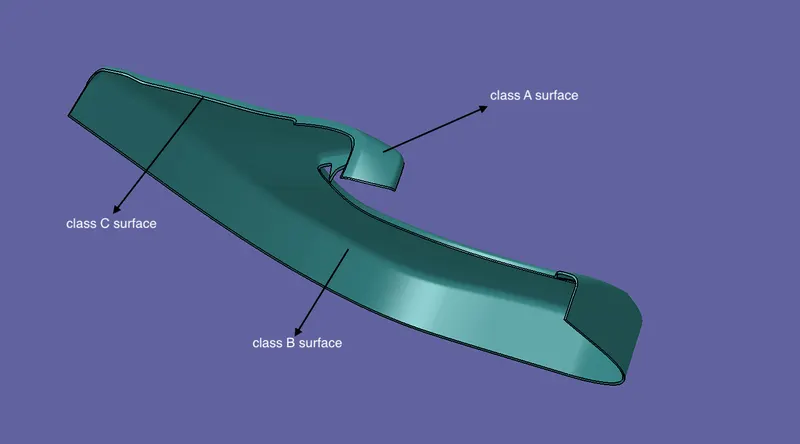
So this same procedure is used to create solid for all the parts.
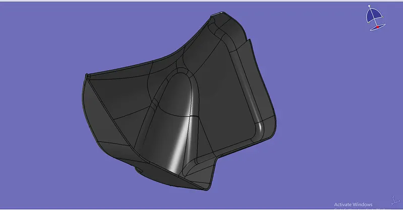
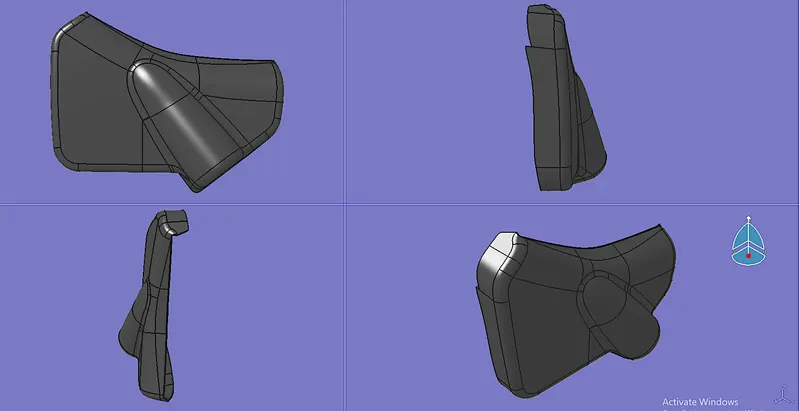
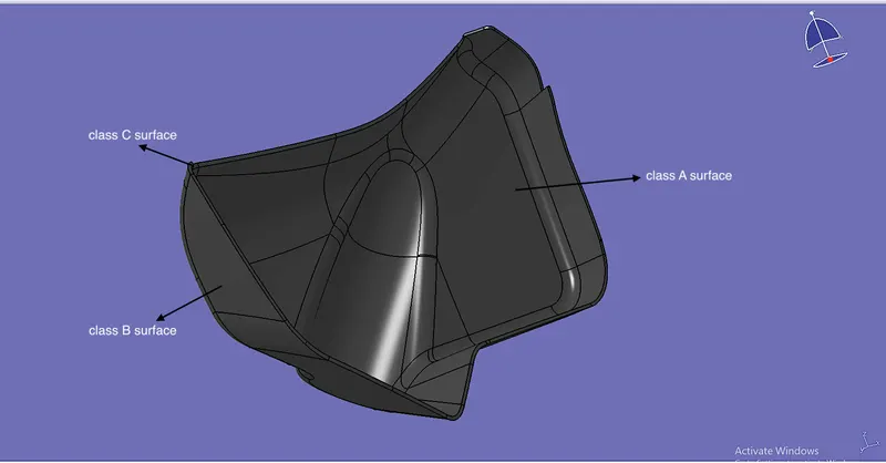
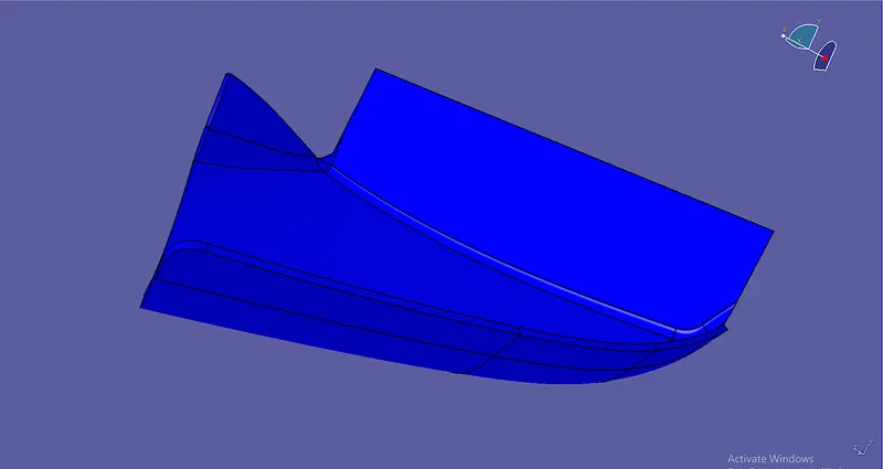
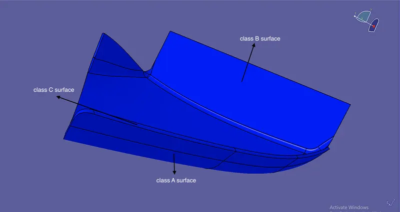
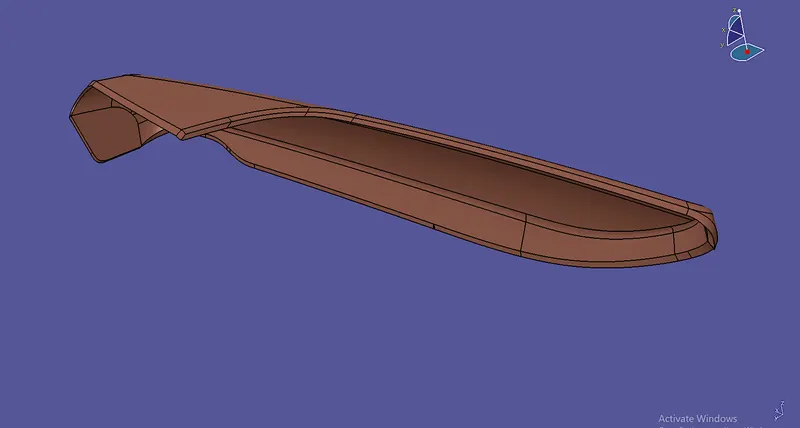
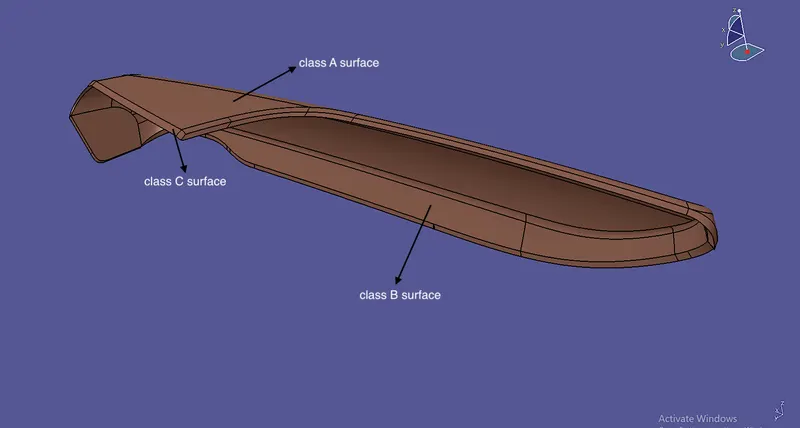
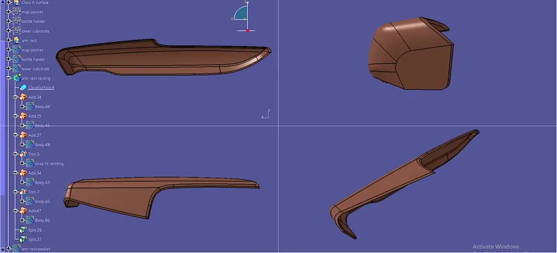
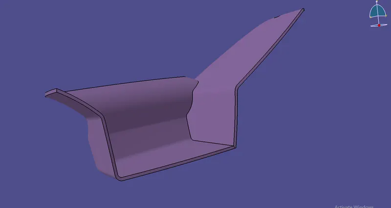
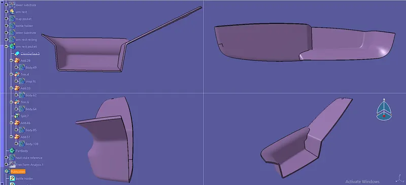
So after creatig the solid for all the components with refering the master section for nominal thickness, Then the B side attachment features was created.
First the attachment features in the lower substrate was created as the every other components created will be fitting and placed in the lower substrate.
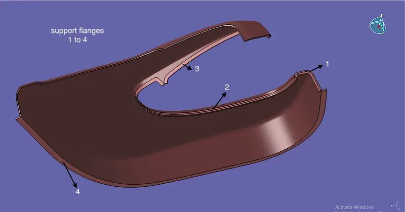
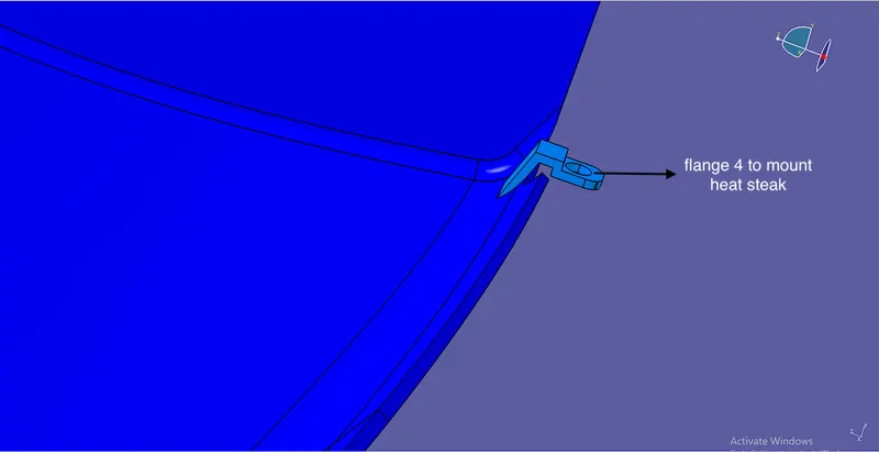
So some support flanges was created to have lookig o some movement and to have support. As creating of flanges the C surface will be hidden and the flage will take the C surface place.
To lock the components created to the lower substrate heat steaks are used. And to arrest the movements locators are used.
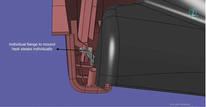
So now first heat steaks was created for an outer dia of 7mm with a hollow of inner dia as 5mm, and to give it some fixing support, ribs are created to support and give some strength to it.
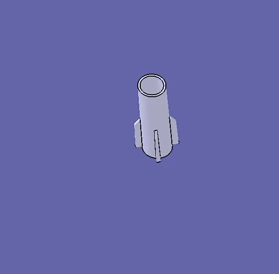
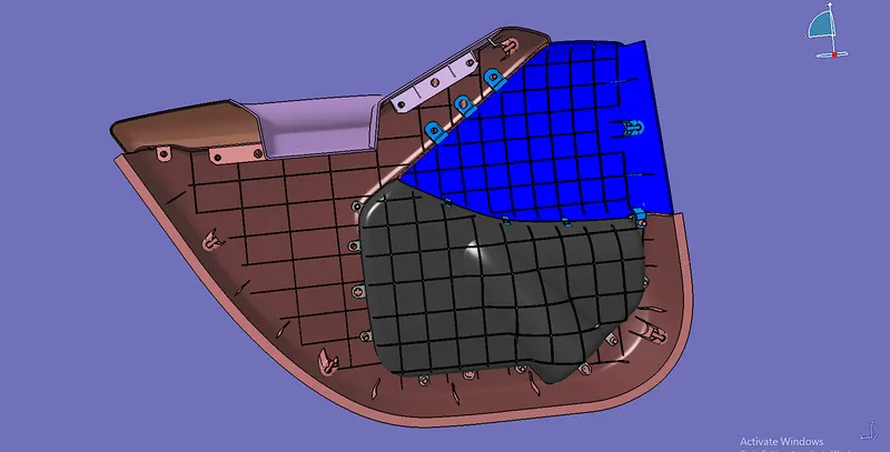
The above shown is a sample of heat steak which was created with reference and alog the tooling axis. Minimum of 2 to 3 heat steaks was required for one component to fix, so some no. of heat steaks was created and attached with the lower substrate.
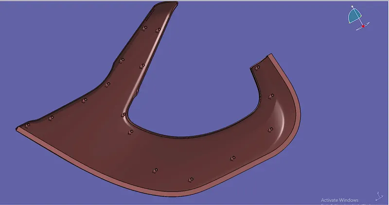
The above shown image shows the places were all the heat steaks was made and placed in the lower substrate.
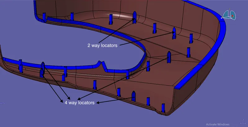
Now locators were created to arrest the movement’s to be occurring for the fixing components. 4 way and 2 way locators are being created for each component to get located. For some components one locator can be used considering its supports so for that one 4 way locator is placed.
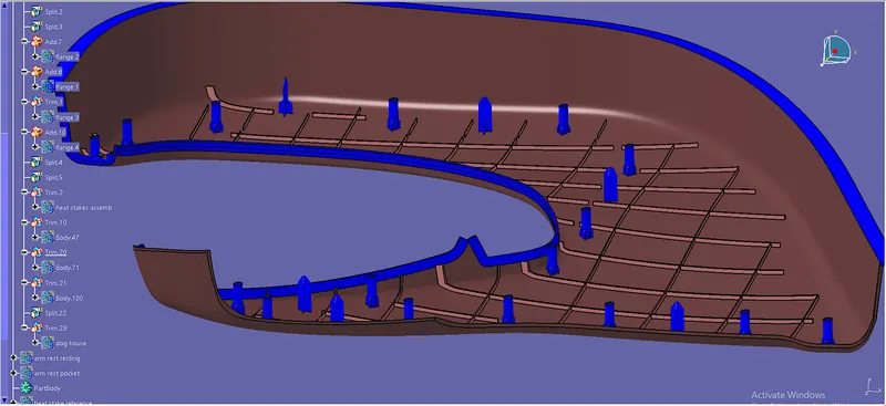
Then to make this component a much stronger and to strengthen it horizantal and vertical run through ribs are used.
To give some more support to the flanges side ribs are used in to strengthen it.
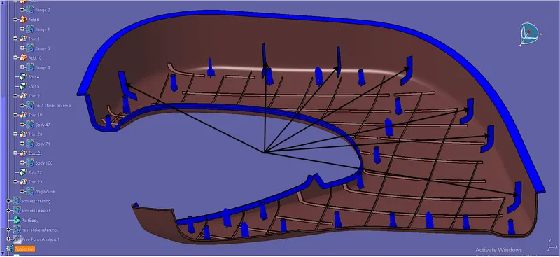
Then to mount the lower substrate to the sheet metal we use push pins and that pushpis are fixed in dog house. So the dog house are created then after.
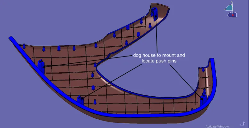
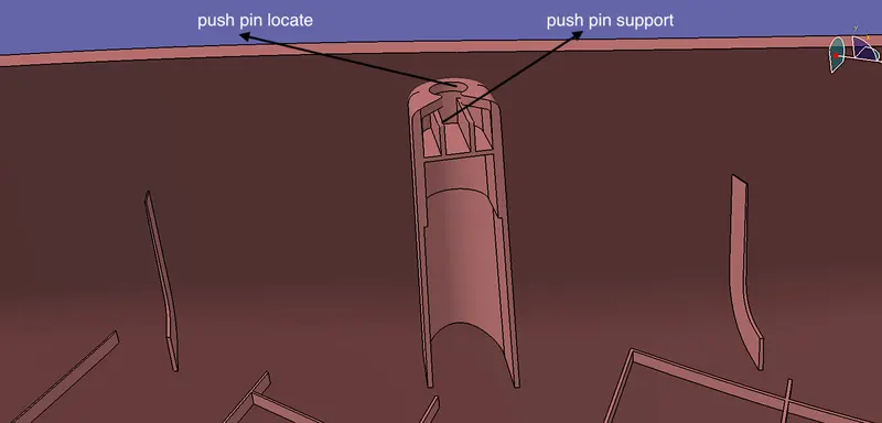
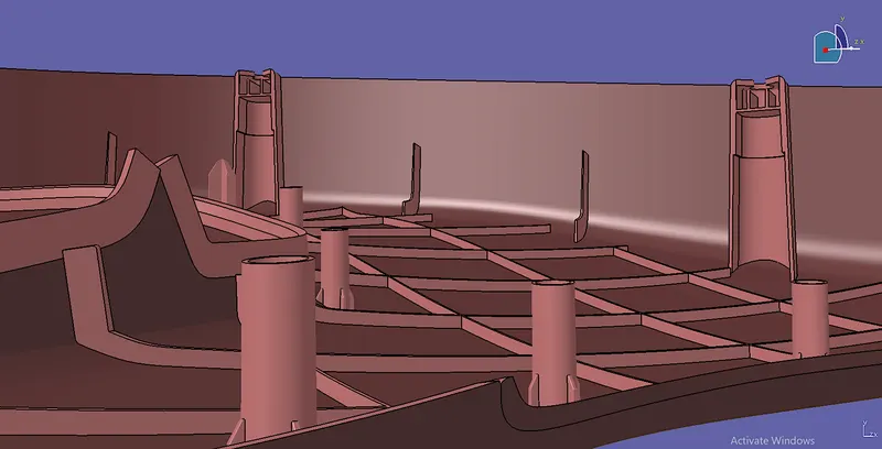
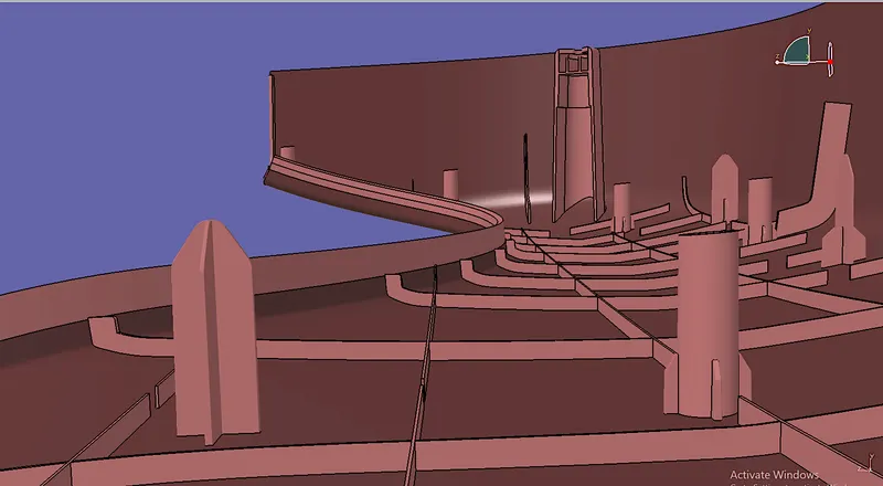
So now the B side attachment features for the bottle holder is created.
As these the next coming components are the fixing ones they were added flanges with heat steaks mount and position to mount locators.
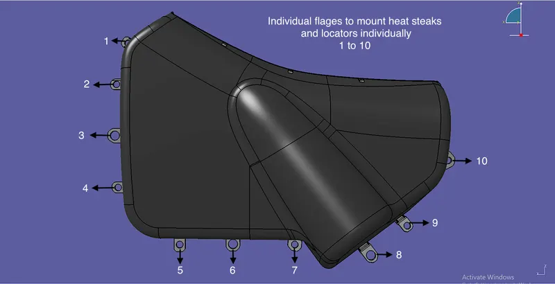
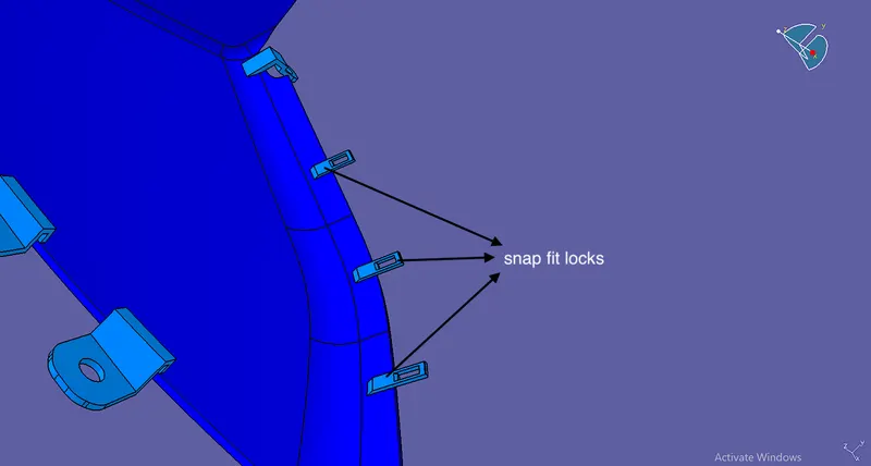
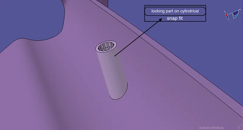
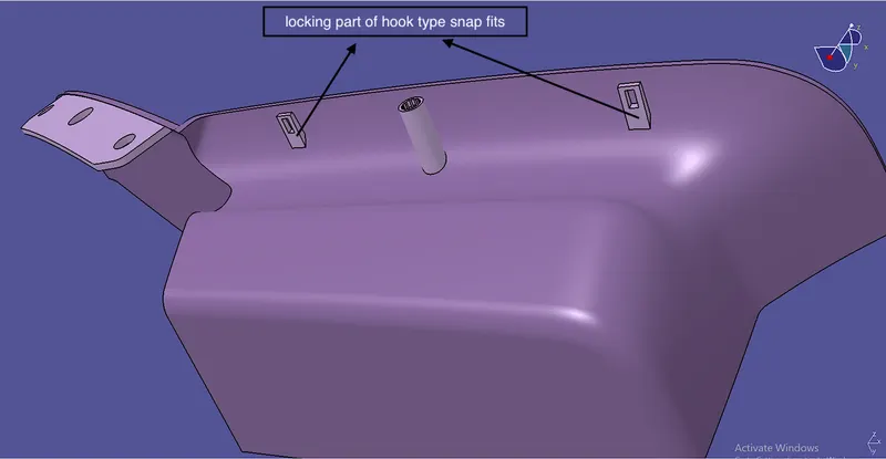
As this lock with the map pocket, to lock this with map pocket we used snap-fits to lock them. There are many snap-fits types I used a buckle type of snap-fit in this component.
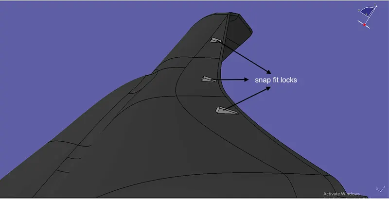
The same procedures was followed to create all the B side features to alla the fixing components.
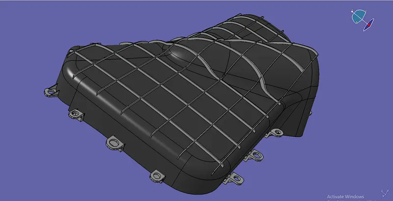
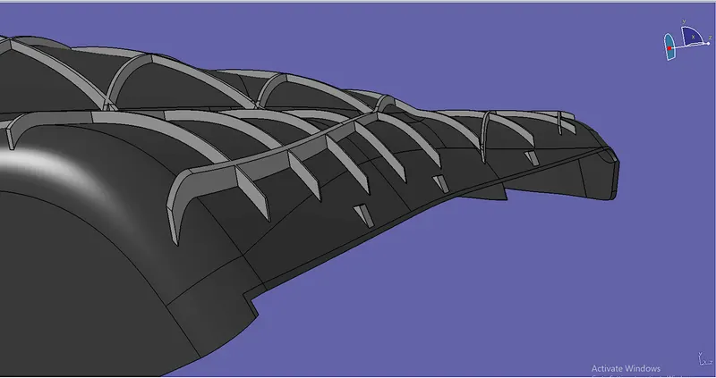
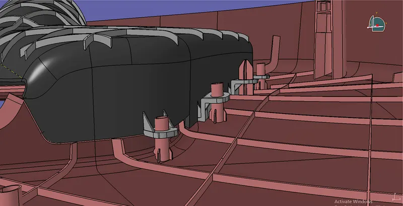
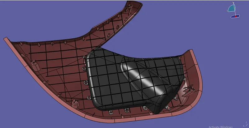
Then the B side features for the map pocket wasa created in the same type by the same procudure.
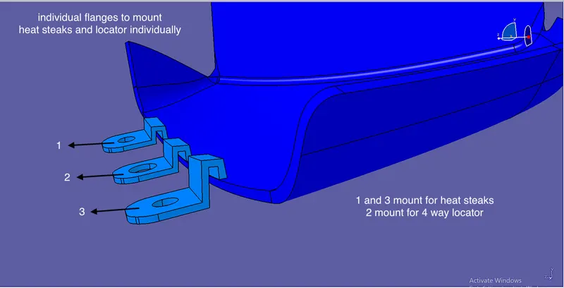
Hooks for the snap-fits.
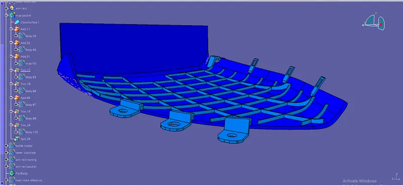
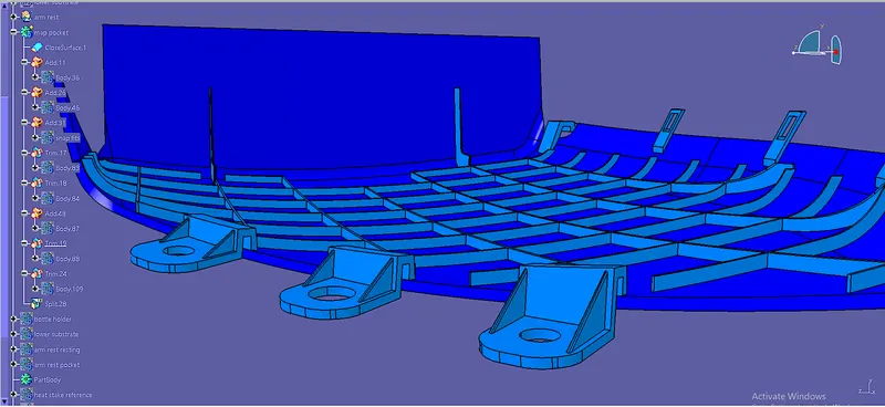
A dog house was also created in map pocket.
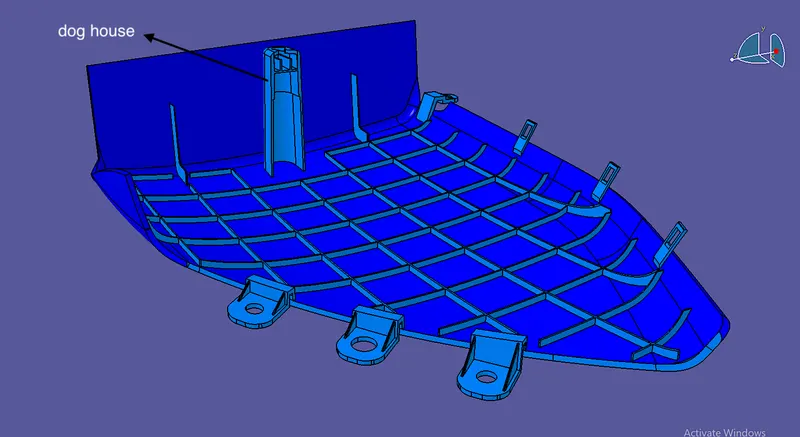
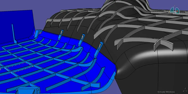
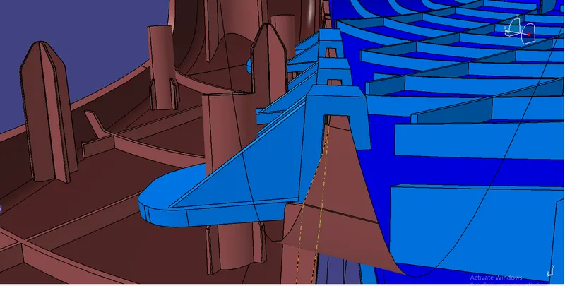
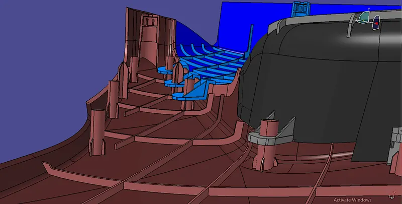
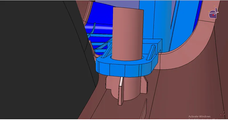
Then next we move on to creating the B side features for the arm rest.
These same procedures was used to create it.
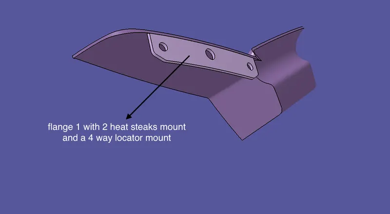
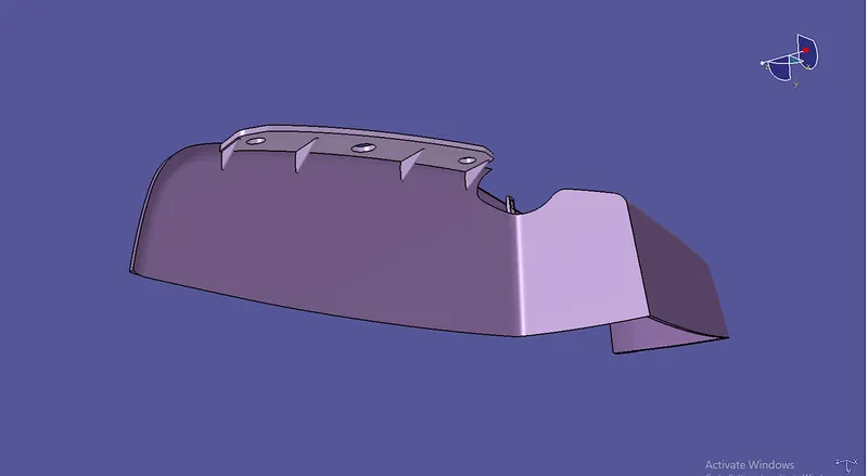
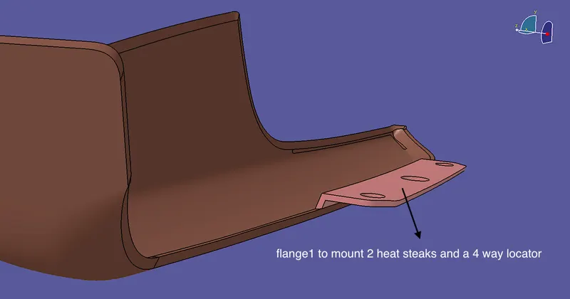
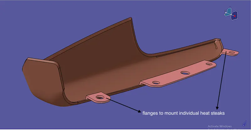
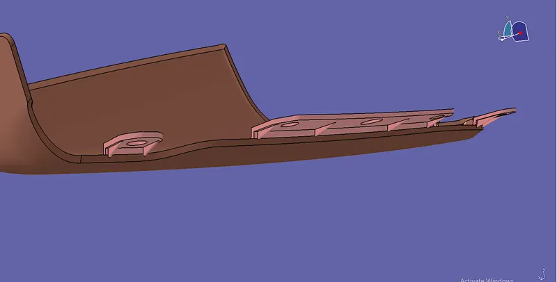
For the arm rest only the flange to mount the heat steaks and locator and the snap-fits are alone created.
In these I made cylindrical snap and hook lock snap was created.
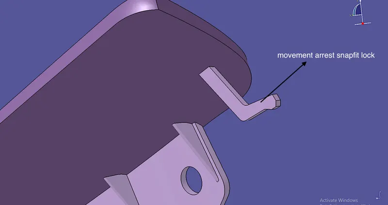
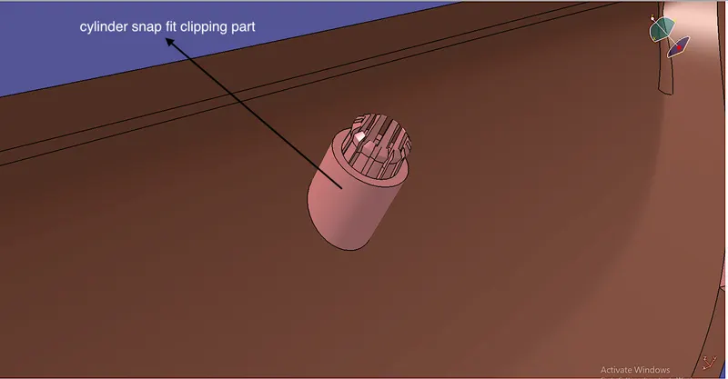
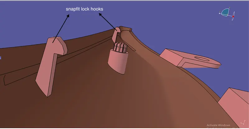
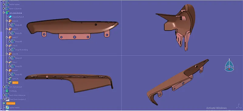
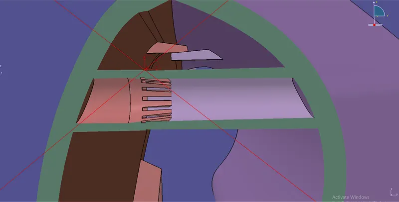
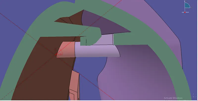
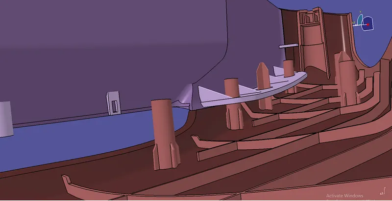
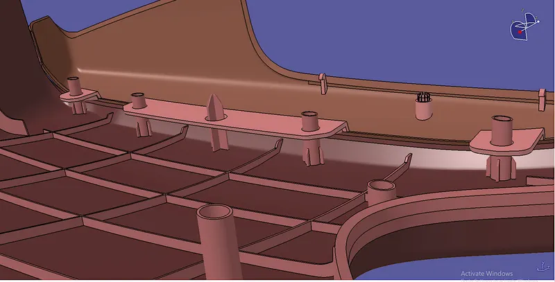
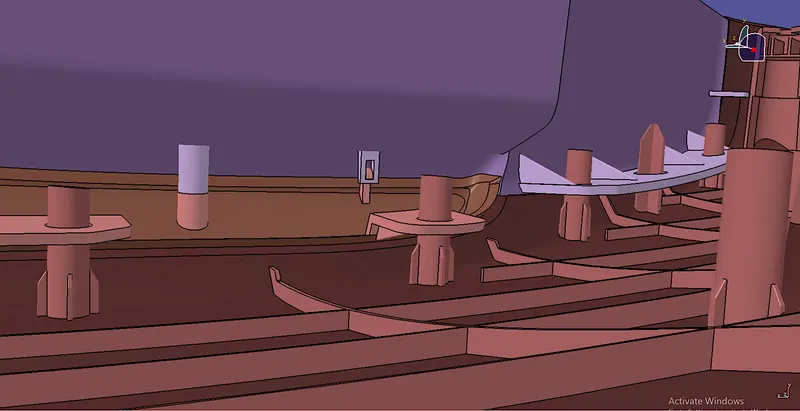
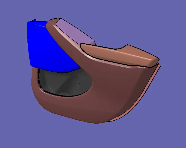
Some final images are shown below after createing B side features for all the components.
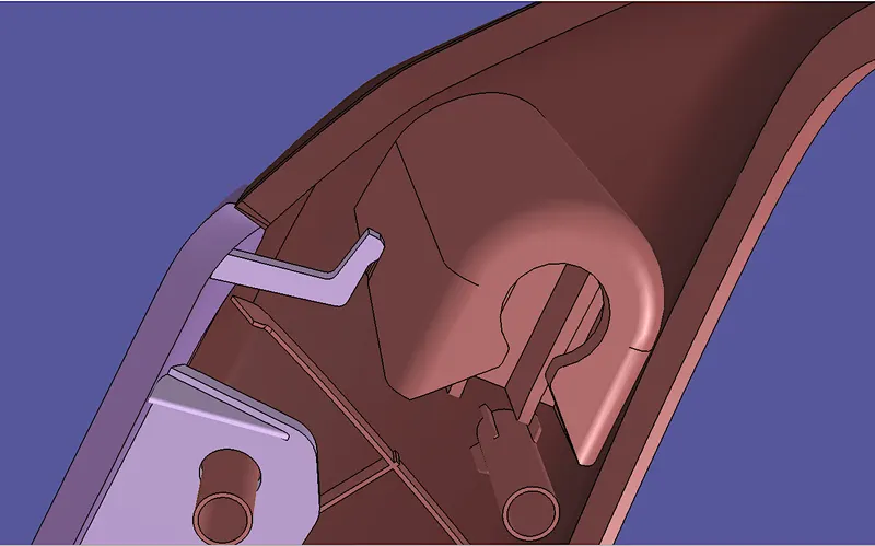
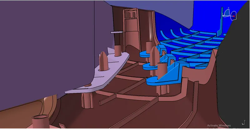
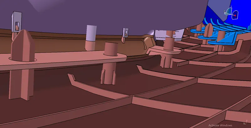
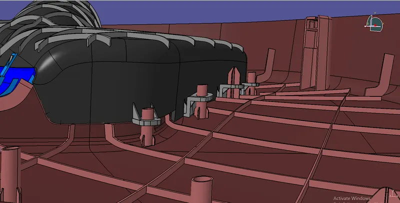
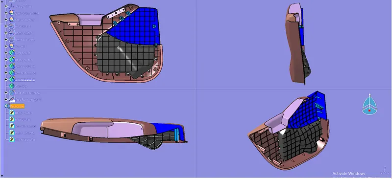
The final output of this project development of plastic components of door trim using the master section given for reference and taking the class A surface and considering the plastic components design features rules.