Week 11 - Final project
| Automotive Plastic Design - DOOR TRIM PANEL |
AIM:
To create solid Plastic Door trim components using the given Class-A surfaces of the components, with nominal thickness and mounting features, complying with the design guidelines in the industry.
OBJECTIVE:
- Create Class-B and Class-C surfaces using the Class-A surface for each component.
- Create a solid part using the closed surface made with Class-A, B & C surfaces.
- Create the mounting features and reinforcement features to the solid part.
- Create a Tooling Axis for the solid part, a Side Core/Lifter Axis if necessary.
- Perform Draft Analysis on the finished solid part using the Tooling & Side Core/Lifter Axes.
GIVEN:
All the given Class-A surface patches of a Door Trim panel are given as input.
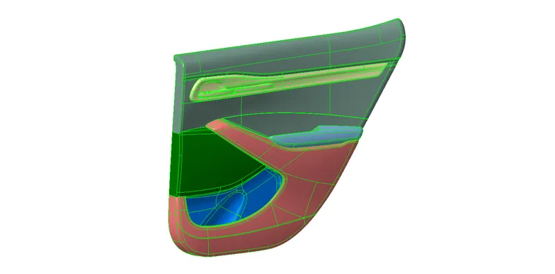
In this project, the Armrest, Map Pocket, Bottle Holder, and Lower Substrate are made. Upper Substrate and the Door Applique are not covered.
The Class-A surface patches are segregated part-wise and put into separate Geometrical sets then joined as shown in the pictures below.
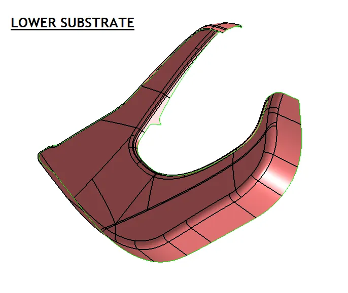
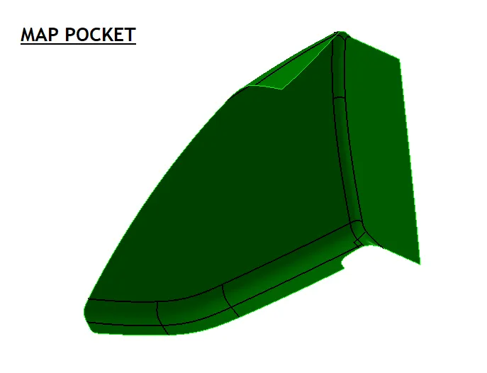
Each part is colored differently to easily differentiate them.
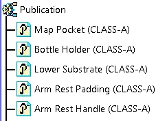
After each part's surfaces are joined, they are renamed with their part name and then Published using the PUBLICATION feature using the command Tools → Publication in the Menu bar. The published entities are stacked at the end, below the Tree Structure under 'Publication' as shown in the image below.
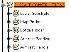
New geometrical sets are created for each part by the same names under a geometrical set named SURFACE CONSTRUCTIONS as shown in the picture below.
OVERVIEW:
Almost all automotive plastic parts are manufactured by a method called Injection Molding, wherein the molten plastic is injected into the cavity of the mold of the part to be manufactured. So, from the manufacturing point of view, the key factors to consider while designing the part are Tooling Axis and Draft angle.
Tooling Axis is the direction along which the mold core or cavity moves. In the design of automotive plastics, the Tooling axis is first created/identified, then a closed surface is created so as to make it a solid.
Draft Angle is the angle given to the walls of a component that is parallel to the Tooling Axis. A draft angle is given so as to facilitate easier ejection of the plastic part after it has been molded. The nominal draft angle is 3°, whereas a minimum of 0.5° is given to ribs, heat stakes, 2-way & 4-way locators, and holes.
TOOLING AXIS:
As mentioned, Tooling Axis is the most important factor to be considered and identified for any part to be injection molded.
- LOWER SUBSTRATE:
A new geometrical set is created by the name, Tooling Axis under (child of) the Lower Substrate geometrical set.
A point is created on the Class-A surface of the Lower Substrate.
An Axis System is created with the point as origin and Default(Absolute) as Reference Axis System.
Viewing the Lower Substrate normal to the global Y-Axis, all the faces of the Class-A surface are visible. This indicates that if the Tooling Axis is to be made along the global Y-axis, the final part will clear the Draft analysis. Hence, a line is created using the Point-Direction type, with the created point and global Y-Axis. The line is renamed as TOOLING AXIS: Lower Substrate and it is also Published using the PUBLICATION feature.
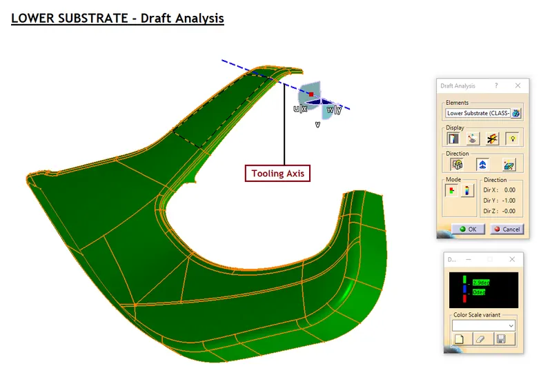
The above image shows the Lower Substrate Draft Analysis where all the surface is green. Hence, with this tooling axis, the lower substrate has a draft angle > 2.9°. - MAP POCKET:
Similarly, the Tooling Axis for the Map Pocket is created along the global Y-Axis, as it also clears draft analysis along the same direction.
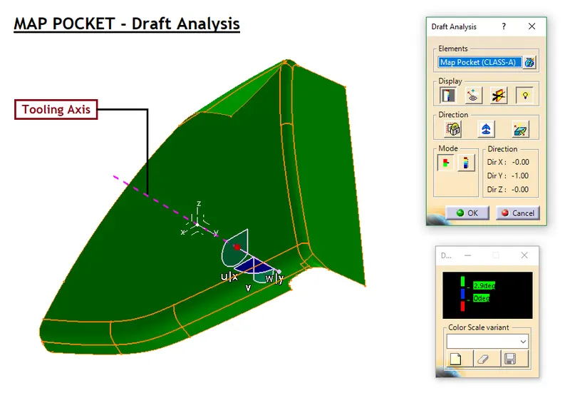
As seen in the above picture, the surface is completely green, which indicates the draft angle > 2.9°. - ARMREST PADDING:
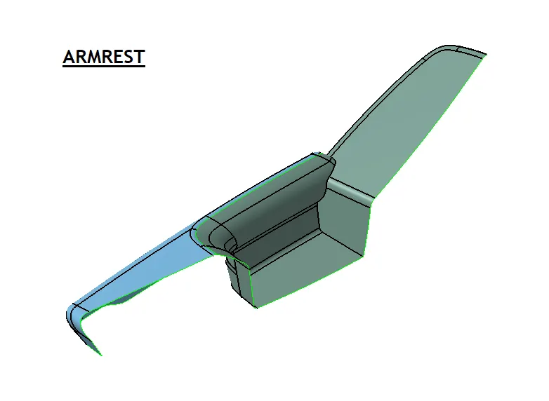
The armrest is split into 2 parts: (i) Padding area and (ii) Handle area.
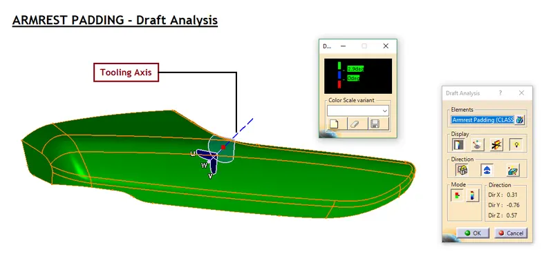
The Armrest padding needed only one Tooling Axis, all the faces were cleared using the same as shown in the Draft Analysis picture above. - ARMREST HANDLE:
The Armrest Handle, however, has few areas of some surfaces that are not cleared using one Tooling axis as shown in the Draft analysis picture below. This creates a necessity for a Side Core Axis so as to successfully manufacture this part.
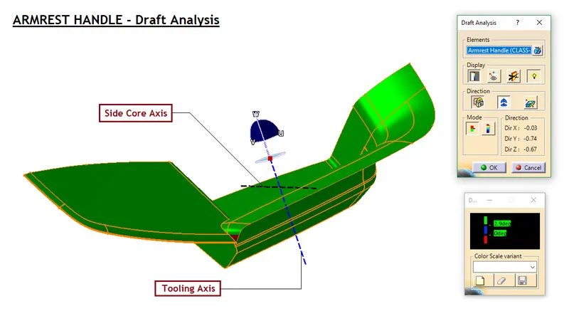
The red area shown in the Armrest Handle Draft Analysis image above is cleared using the Side Core Axis. - BOTTLE HOLDER:
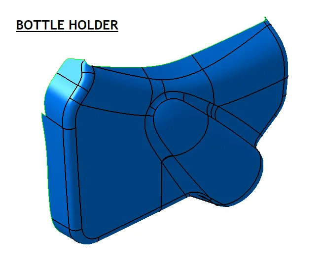
One of the sides of the bottle holder is perpendicular to the global Y-Axis. Hence, this part would need a Side Core Axis to completely manufacture a solid part.
The absence of a positive draft angle on one of the walls of the bottle holder is shown in the Bottle Holder Draft Analysis picture below.
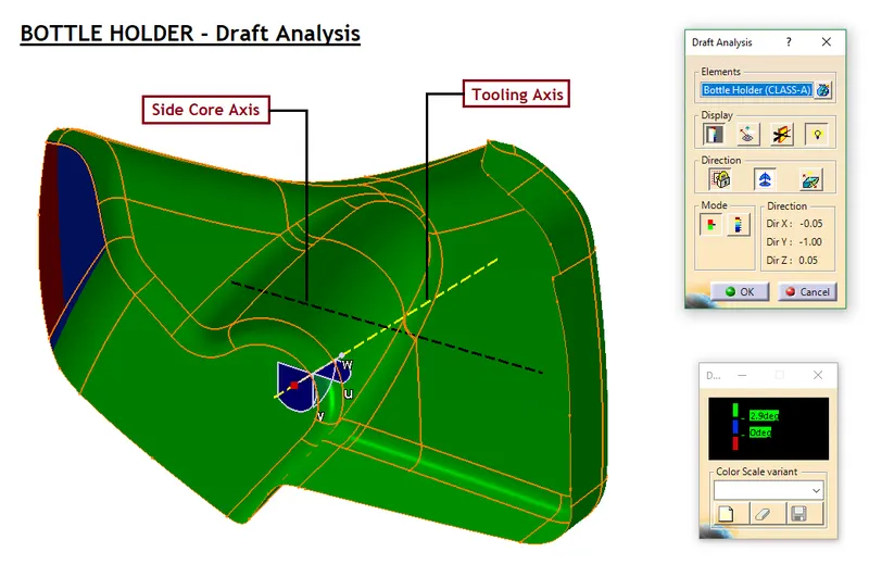
The area in green has a draft angle > 2.9°.
The area in blue has a draft angle between 0° and 2.9°.
The area in red has a draft angle < 0°.
SURFACES (CLASS - B & C):
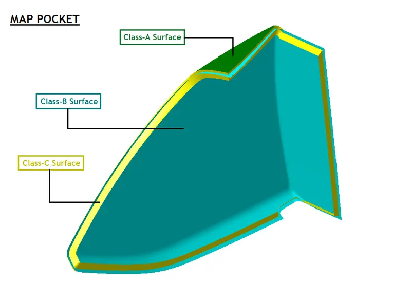
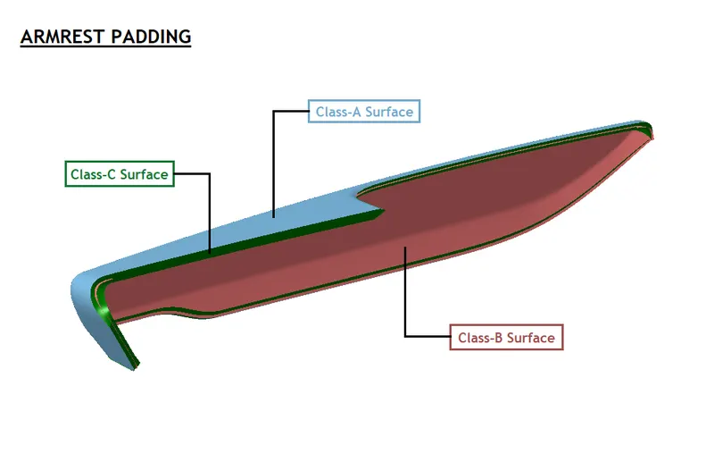
In Automotive plastic design, to create a closed surface of a component, we need CLASS - A, B & C surfaces.
- The Class-A surface is the surface that can be seen and touched after the part/component is fixed on the vehicle. Hence, this surface should be aesthetically pleasing to the passenger.
- Whereas, a Class-B surface is on that is completely opposite to Class-A; it cannot be seen and touched after the component is fixed on the vehicle. However, this is the side of the component that has all the engineering features of the component (i.e,) reinforcements, heat stakes, flanges, ribs, and so on. This surface is parallel to the Class-A surface.
- The Class-C surface is the one that connects Class-A and Class-B together.
Since, the Class-A surface is given as input, the Class - B & C surfaces are to be created.
- LOWER SUBSTRATE:
A geometrical set is created under Lower Substrate geometrical set by the name, B-Surface. The thickness of the final part is measured using the master section given along with the Class-A surface patches. It is measured to be 2mm.
The Class-B Surface for the Lower Substrate is created by offsetting the Class-A surface by 2mm using the Offset feature in the Surface Workbench.
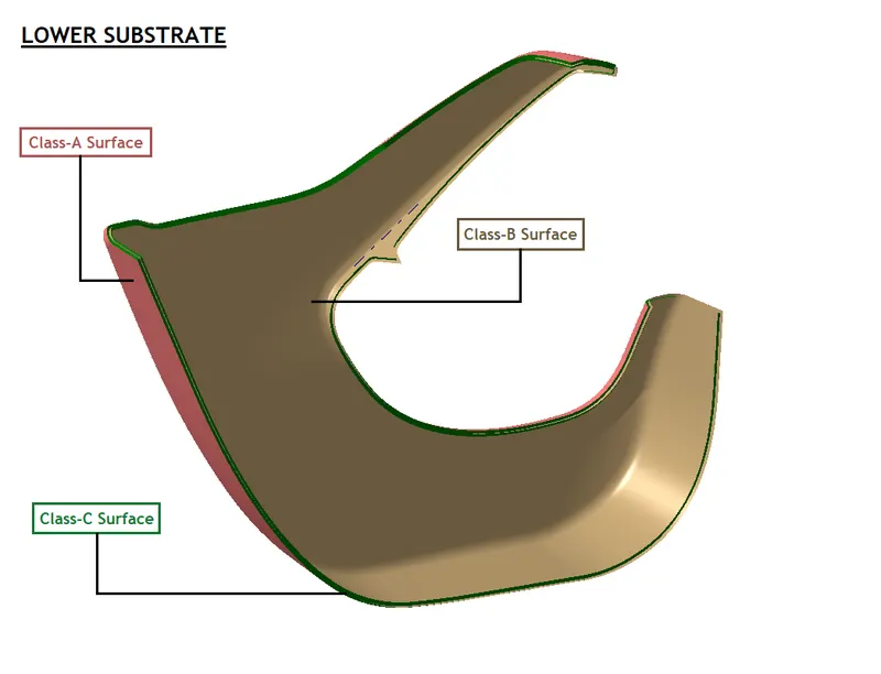
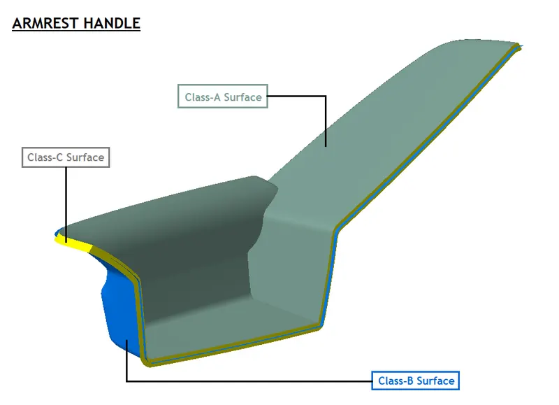
Using the boundary of the Class-A surface, the Class-C surface is swept at an angle that intersects the Class-B surface and that clears the Tooling Axis as shown in the picture above. - MAP POCKET:
Similarly, the Class-B is created by offsetting the Class-A surface by 2mm inwards and the Class-C surface is swept in angles that intersect the Class-B and also clears in the Tooling Axis of the Map pocket. Sometimes the C-surface is also created using the Multi-Sections Surface feature.
- ARMREST PADDING:
- ARMREST HANDLE:
- BOTTLE HOLDER:
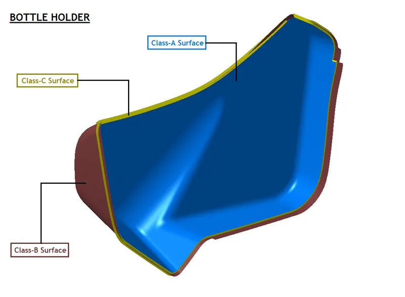
All three surfaces of each part are trimmed together to form a closed surface.
SOLID PART:
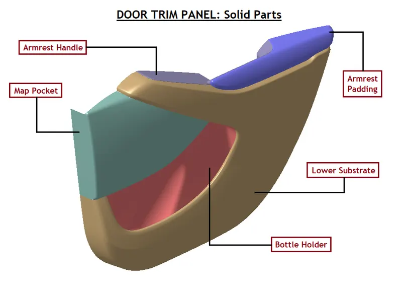
A new body is created for every part and solids are created using the corresponding closed surfaces.
ENGINEERING FEATURES:
Engineering features are those that add reinforcement and help fix the plastic part onto the vehicle. Flanges, Ribs, Locators (2-Way & 4-Way), Heat stakes, snap fits are some engineering features used in the plastic design.
For the most part, all the engineering features are created along the Tooling axis and drafted for a minimum of 0.5° to facilitate easier manufacturability.
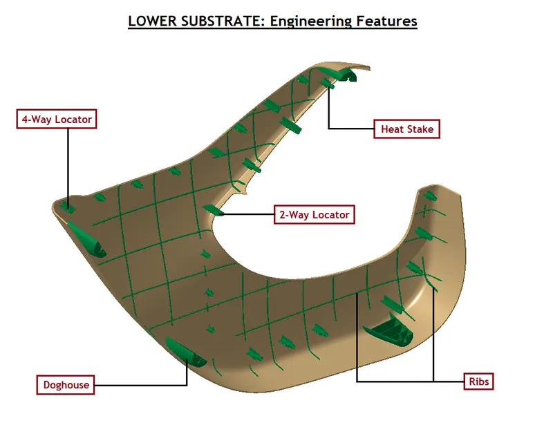
1. LOWER SUBSTRATE:
Since the lower substrate is the biggest part in the Door trim on which the rest of the parts are fixed, the attachment features are created for this part first.
- FLANGES: First, flanges with holes are made on the counterparts to accommodate the locators and heat stakes.
- LOCATORS: There are 2-Way & 4-Way locators in plastic design. A 2-Way Locator is used to stop the counterpart from moving in one direction. Whereas, a 4-Way Locator stops the part’s movement in 2 directions. So for any component to be fixed on another part, it needs at least one locator to position it.

The Locator’s height should be higher than the other attachment features, say heat stakes.
All the locators are drafted for a minimum angle of 0.5°. - HEAT STAKES: Heat stakes are cylindrical protrusions with circular cavities. These are like welding but in plastic components. Hence, they arrest the counterpart from moving in all directions.
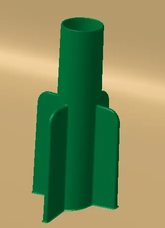
The Heat stakes and its ribs are also drafted for a minimum draft angle of 0.5°. - RIBS: Ribs add strength to parts that they are attached to. For instance: Flanges are like cantilever beams where one end is free hanging. To avoid them from breaking, ribs are used. Ribs are also used for heat stakes, as heat stakes used here are hollow and hence need reinforcement.
- DOGHOUSE: They are used as supporting features. They also help avoid sink marks on the Class-A Surface. Sometimes other attachment features such as locators, heat stakes, snaps, etc. are mounted on the doghouses. Here, it is used to mount the Door Trim panel onto the sheet metal door.
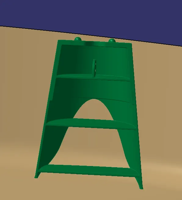
The dog house is cored out from the bottom to avoid sink marks on the Class-A surface.
A bush-like stopper is provided at the top of the dog house so that when the panel is mounted on the sheet metal door, the stopper butts on the sheet metal.
2. MAP POCKET:
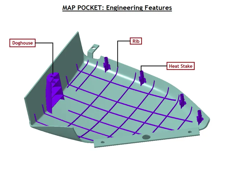
The Map Pocket is mounted on the Lower Substrate. So first, flanges with appropriate holes corresponding to the engineering features on the lower substrate are made.
Since one of the sides of the Bottle Holder lies on one of the sides of the Map Pocket, a few heat stakes are made on the Map Pocket for the Bottle Holder.
A Doghouse is also made here to mount the door trim onto the sheet metal door.
3. ARMREST PADDING:
The Armrest Padding part mounts on the lower substrate. So appropriate flanges with holes are made corresponding to the Locators and the Heat stakes on the lower substrate.
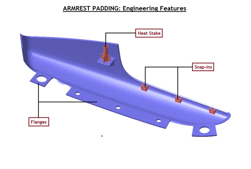
One heat stake and three snap-ins are made to fix the Armrest Handle with this part.
4. ARMREST HANDLE:
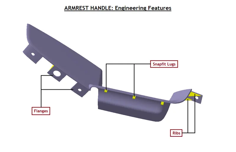
The Armrest Handle part mounts on the lower substrate and also with the Armrest Padding. Flanges, Snap Lugs are made.
5. BOTTLE HOLDER:
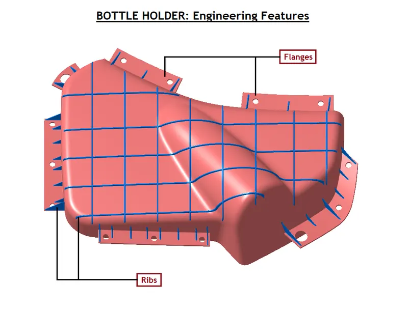
The Bottle Holder, just like the lower substrate, is the part with most engineering features. It has the most number of ribs and flanges, as it is mounted on the lower substrate and the map pocket.
DOOR TRIM PANEL - FINAL:
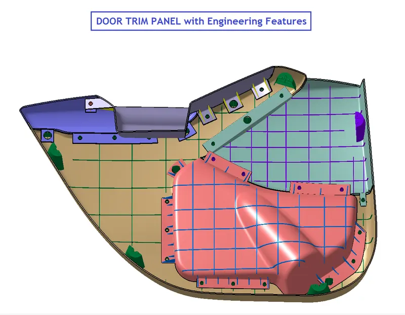
Using the engineering features, all the parts are attached together and then mounted onto the sheet metal door. The attachments are shown in the images below.
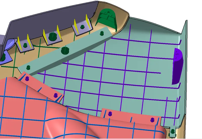
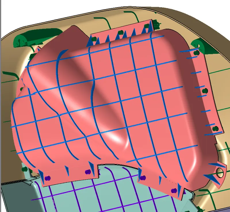
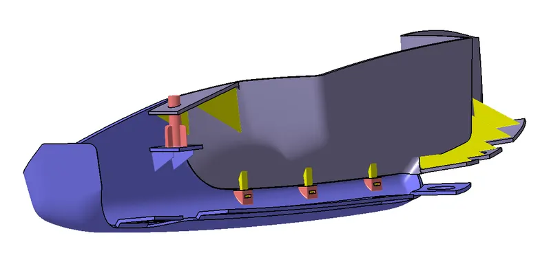
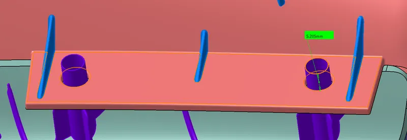
In the images above, it can be clearly seen that all the locators are taller than the heat stakes and all the heat stakes are approximately at a similar height from the upper surface of the flanges.
The assembled door trim panel is shown in the image below.