Week 11 - Final project
DOOR TRIM PANEL:
Door panels serve as an interface between the interior of the car and the inner workings of the door, and between vehicle occupants and the door. They are expected to meet a variety of design specifications regarding safety, aesthetics, and functionality. In addition, they are expected to continue the material theme of the dashboard and pillars while concealing intricate electrical and mechanical components for operating locks, windows, and other features.
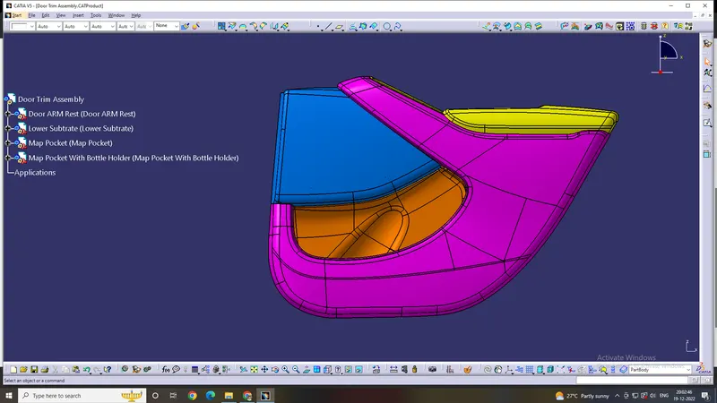
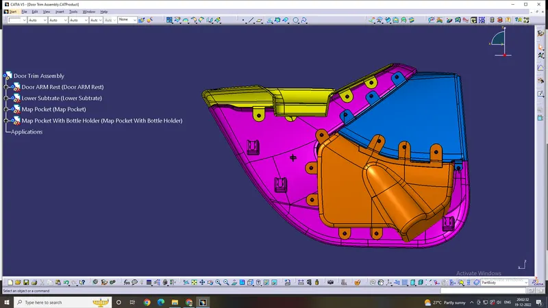
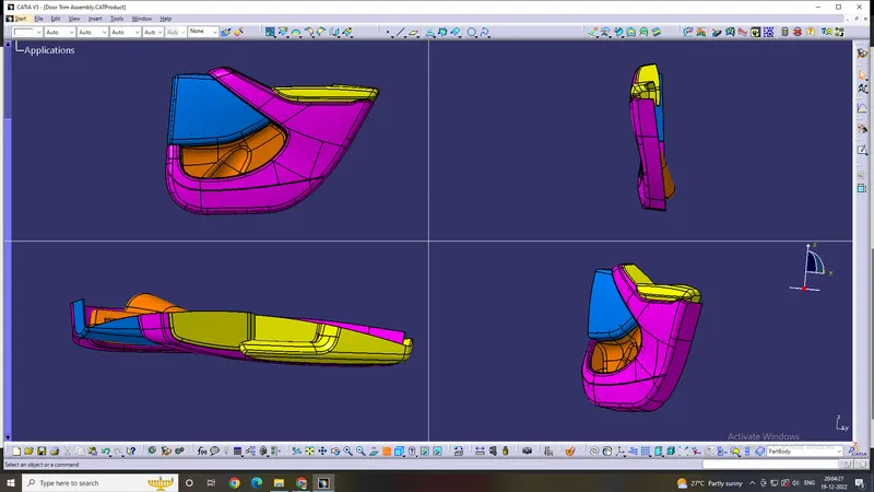
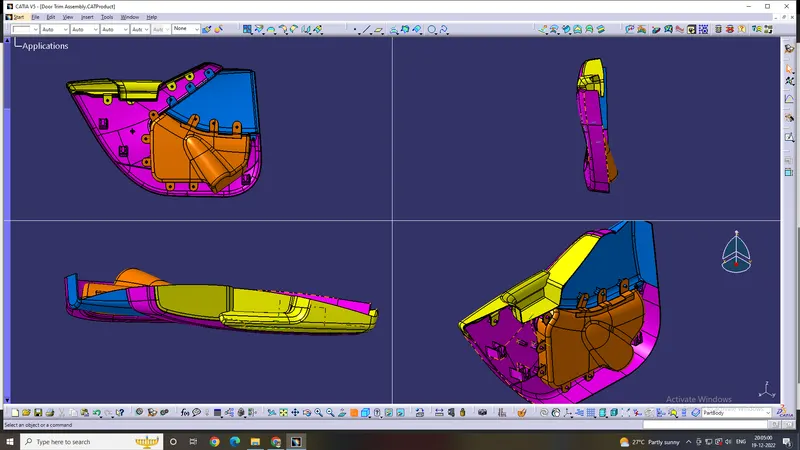
In this project, an inner car door panel is given with class A surface, to create the door trim panel it is divided into sub-parts namely, a lower substrate, inner map pocket, outer map pocket, and door armrest.
Our basic approach to make a plastic model from class-A surface should be:
- Run draft analysis
- Make tooling axis
- Make B surface
- Make C surface
- Trim all together and make it solid.
1.WHAT IS CLASS A SURFACE?
CLASS A SURFACE IS A VISIBLE SURFACE WHICH SURFACE SEENBYUSINANYPRODUCT.IT LOOKS STYLER AND ATTRACTIVE.AND A BEST FINISHINGYOUSEENINCLASSA SURFACE.
2. DRAFT ANALYSIS OF CLASS A SURCAE?
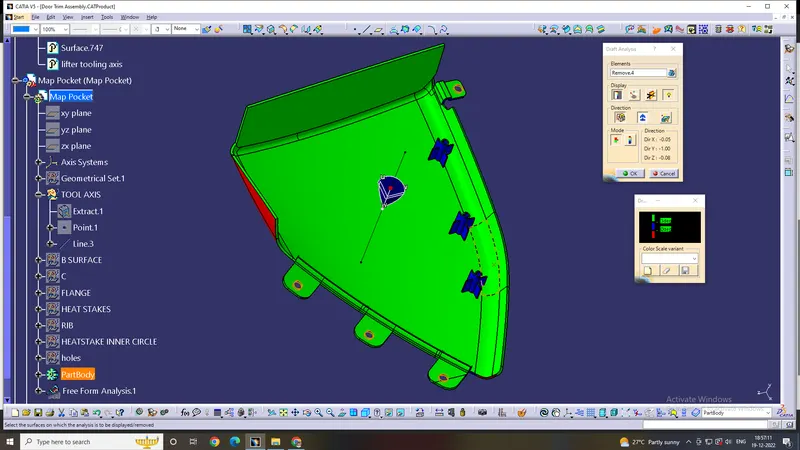
FIRSTLY ON THE REFERENCE OF SURFACE AND TAKE NEWGEOMETRICALSET,AFTERTHAT WE EXTRACT A FLAT SURFACE AND PLOT A POINT ON SURFACE BYUSINGPOINTONSURFACE OPTION AFTER THAT MAKE A LINE ON POINT BY USING NORMALTOSURACEOPTION. NOW,WE GO TO INSERT SELECT ANALYSIS ANDFEATUREDRAFT ANALYSIS OPTION SELECT SURFACE DRAG THE CAMPUS ON LINE ANDSWITCHONTHE USES THE CAMPUS TO DEFINE THE NEW CURRENT DRAFT DIRECTIONOPTION, AFTER
THAT IF YOUR BOTH SIDE OF SURFACE IS GREEN NOW YOUR SURFACE IS READYTOMAKESURFACE B.
3.TOOLING AXIS & DRAFT ANALYSIS:
TOOLING AXIS:
Tooling axis is the axis along which the core and cavity opens and closes. It is very important to define the tooling axis in the first step while designing a component as it is the main component which helps us to run draft analysis on class-A at initial stage to see if we can move ahead. Also for later stage, tooling axis is the direction along which class-C surface and the draft to the components is given.
In this model we have a tooling axis in the perpendicular direction to the entire door trim that is y-direction in the model. It is very evident that switch bezel will require a side core, so another tooling direction is made specifically for switch bezel. Apart from these two tooling axes we also have a side core tooling axis for dog house.
DRAFT ANALYSIS:
Our first step before starting the model should always be to check is the surface has enough draft that it will not create any problems while ejecting from the mold. This seems like a big task as we have to foresee something that will come at very later stage. But this is done by a small process called draft analysis. This analysis tells us whether our component will be safely ejected in the tooling axis we have provided. Some components require side core where there are under undercuts, holes or projections on the side walls, so for this we need a different tooling axis and a different analysis is required to check those areas. Draft analysis shows color codes which are defined by the user for different values which also are defined by the user. These colors help us to analysis if the component is clearing the analysis and we are good to go ahead or not. In case the component fails the analysis for class-A then we have to submit the draft analysis report to the higher authority so that the surface of the component can be improved. Failing analysis simply means that the component does not have the required draft value it must have. In case our solid model which we develop, fails the analysis at some parts then we have to correct it ourselves.
We have to make sure that our entire model is green which means it is clearing the analysis. So we have to run analysis for class-A, solid model and other B-side features as every single component, regardless of its size should be ejected safely from the core.
4.WHAT IS CLASS B SURFACE?
CLASS B SURFACE IS A HIDDEN BACK INSIDE PART WHERE MANYSUPPORTSANDMARKS ARE VISIBLE BUT THIS A HIDDEN FACE SO THAT IS NOT A ISSUE. CLASSBSURFACE IS ALSO A THICNESS OF THE PART.
5.CLASS B CREATION?
FIRSTLY EXTRACT ALL THE FLAT SURFACE AND UNTRIMALL THIS AFTERTHATWEEXPTRAPOLATE ALL THE SURFACES AND TRIM AS WE NEED AFTER THATWEMEASUREALL THE RADIUS FROM SURFACE A AND GIVE THE RADIUS IN SURFACE B.NOWYOURSURFACE B IS READY.
6.WHAT IS CLASS C SURFACE?
THE COMBINATION OF CLASS A SURFACE AND CLASS B SURFACE IS CLASSCSURFACE. NOW WE CAN SAY THAT FINAL SURFACE IS A CLASS C SURFACEINWHICHCLASS A SURFACE ,CLASS B SURFACE AND THICKNESS IS ALSO PRESENT.
7. CLASS C CREATION?
SELECT ALL THE BOUNDARY AFTER THAT SELECT SMOOTH CURVE TOSMOOTHTHEBOUNDARIES NOW WE SELECT SWEEP COMMAND AND SELECT GUIDE CUREANDANGLEGIVE DRAFT ANGLE AND SELECT WHERE IS ANGLE EXTERIOR OR INTERIOR. NOWOFFSETB SURFACE HOW MANY YOU WANT WITHOUT PROVIDING RADIUS ANDTRIMWITHTHWBOUNDARIES THAT YOU MAKE AND NOW WE FOUND CLOSE SURFACE.
8. FINAL SOLID BODY DRAFT ANALYSIS?
GO TO PART DESIGN CHOOSE SOLID OPTION SELECT PART NOWYOURPARTISBECOME SOLIDE AFTER THAT UNHINE THE LINE WHICH U MAKE IN DRAFTANALYSISINCLASS A SURFACE AND WE GO TO INSERT SELECT ANALYSIS AND DRAFTANALYSIS
OPTION SELECT PART DRAG THE CAMPUS ON LINE AND SWITCH ON THE USESTHECAMPUS TO DEFINE THE NEW CURRENT DRAFT DIRECTION OPTION, AFTERTHATIFYOURBOTH SIDE OF SURFACE IS GREEN, THE DRAFT ANALYSIS IS DONE SUCCESSFULLY
9. JUSTIFICATION OF MANUFACTURING?
DRAFT ANGLE IN PART DESING MUST BE 3 DEGREE SO THAT WE EASILYEJECTTHEPART WITH FRICTION BETWEEN PART AND CORE OR CAVITY.DRAFT ANGLEISMOSTIMPORTANT IN ANY PRODUCT DESIGN.
1. DOOR ARM REST-
Door Arm Rest as the name says it is the part where the driver or the Passenger can rest their hand on. It maycome with a soft touch surface such as leather, cloth or any soft material as a wrap around.It mayalsohousevarious electricals such as the Power Window switches, Mirror adjustment switches etc.It maycomewithasmall storage for coins or sunglasses.
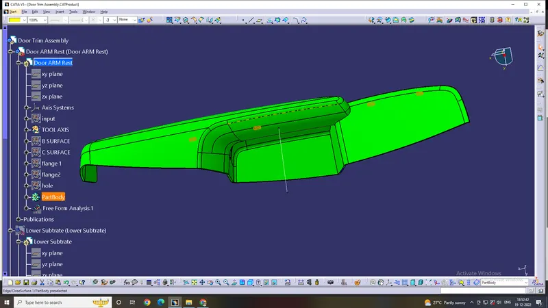
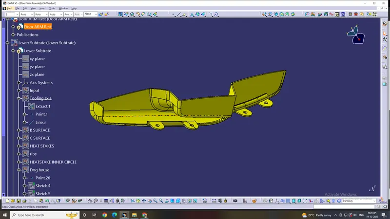
2. LOWER SUBSTRATE-
Lower Substrate is the encapsulating aesthetic Part used in the door panel.It may house various featuressuchas Wirings, Speakers and other sheet metal components behind it.
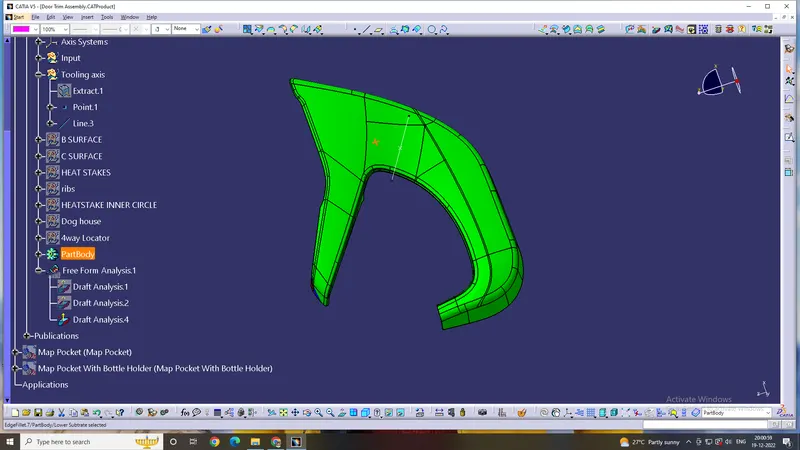
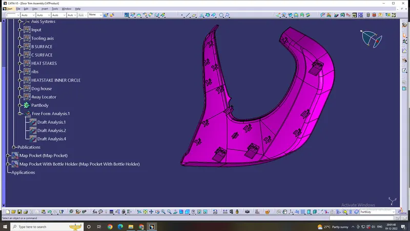
3.MAP POCKET-
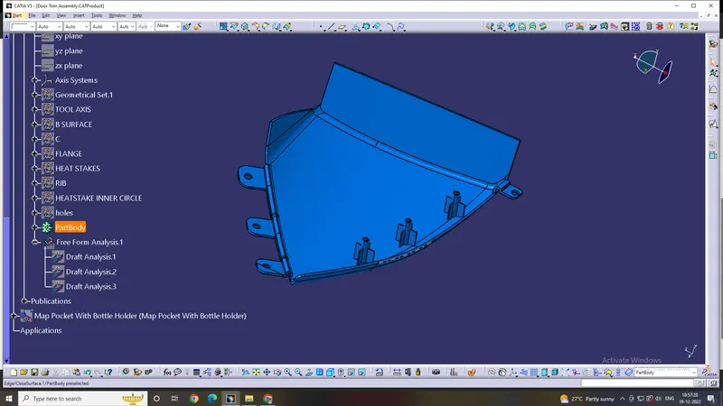
Map Pockets are genrally used as storage space on the door.In this case The Map Pocket is dividedinto2sections the upper and LowerThe Upper Section acts as an enclosure from the inner parts andfor aestheticsonly
4. MAP POCKET WITH BOTTLE HOLDER-
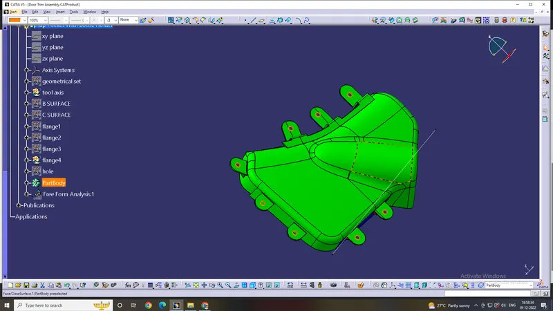
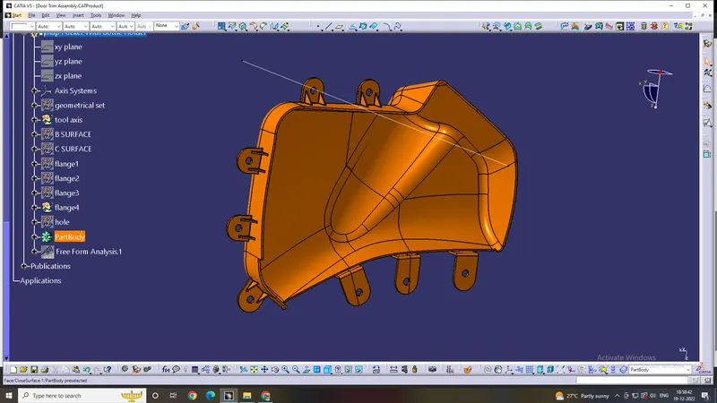
Map Pockets are genrally used as storage space such as a bottle Holder, Umbrella Holder etc. onthedoor.The Lower Section of Map Pocket development is shown in further steps.
Creating B Side Features--
- HEAT STAKES AND RIBS--
* A circle of diameter 4.5mm was made and thickened outside 3mm to get a 7.5mmdia. circle outside. Ribswere added on both sides for strength to the heat stake. 40mm ribs were provided.Multiple heat stakesweremade using translate function on various areas of the doghouse. These heat stakes support the bottleholder,map pocket and door armrest.
- DRAFT ON HEAT STACKS AND RIBS--
* A draft of 0.5 was given to the heat stakes and their ribs. Note that inside draft for the stake will beintheopposite direction to the outside. Finally, the heat stakes were union trimmed with the lower substrate.
- DOG HOUSES---
* 3 doghouses were added on the lower side of the lower substract. we make axis systemand makearectangle30x30mm we pad this 60mm now we gives draft on 1.5mm bt tool axis and shell fromthe inner side.afterthis we copy a first skecth and offset 1.5mm for making coring portion after that we draft on 0.5coringsection by lifter axis. after that we made ribs on dogb house along the front face a thick ness of ribis1.5mmand give draft 0.5 on rib by lifter axis.after by the help of user pattern i placed 3 dog house indifferent pointat last we perform union trim and add dog houses in lower substract.
- FLANGES FOR MAP POCKET,MAP POCKECT WITH BOTTLE HOLDERANDARMREST--
* FOR MAKING FLANGES FIRST WE CREAT A LINE AND AXIS SYSTEMAFTERTHATWESKETCH AND EXTRACT THE UPPER SIDE OUTER LINE AND SWEEP SKETCHALONGTHE EXTRACT LINE AFTER THAT MAKE A SWEEP STRAIGHT AFTERTHATTAKEATOP PLANE AND SKETCH FLANGS AND EXTRUDE THIS SKETCH ANDSPLITTHEMAFTER THAT GIVE THICKNESS, RADIUS AND SUPPORT. AT LAST PERFORMUNIONTRIM TO JOIN FLANGES IN THE COMPONENT. AND MAKES A HOLES INFALNGESFORHEAT STACKES.PLOT A POINT AND MAKE 3D CIRCLE AND POCKET THEM.