Week 11 - Final project
AIM-We have to create a CAD model of a side door trim panel from a given class A surface and master section.
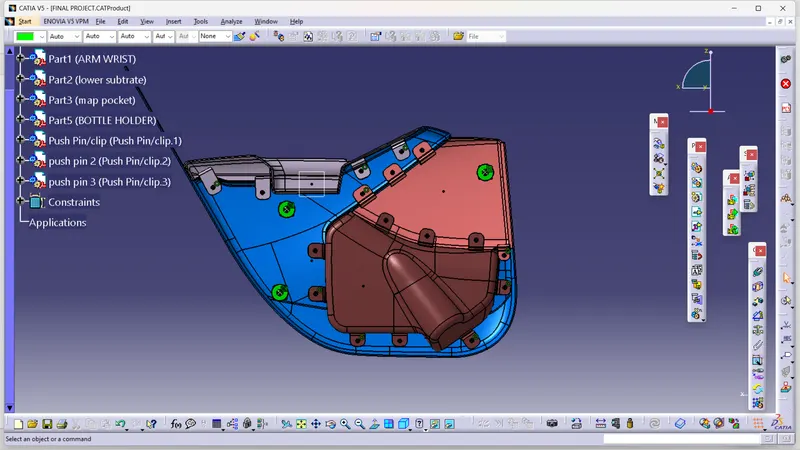
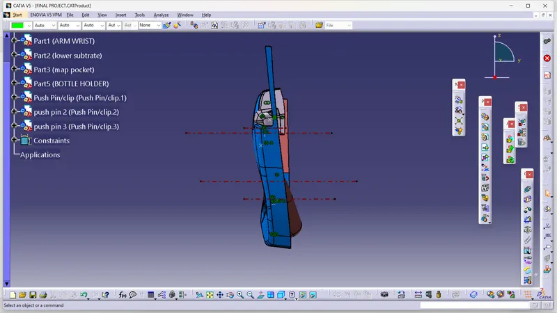
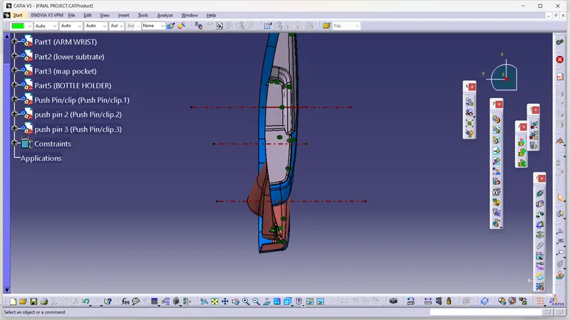
Input - We have received the input as master section and 4 parts of door panel
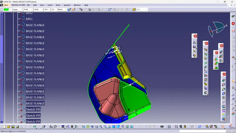
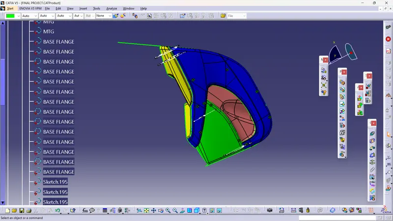
STEPS WE WILL FOLLOW
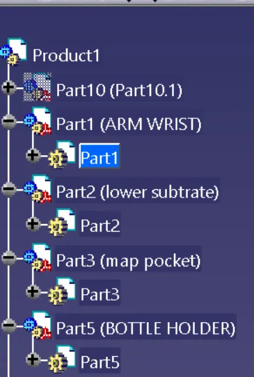
- First we separate each 4 parts into separate parts.
- We will work on each part and create tooling axis, B Surface , C surface and Closed body
- We work B-Features
- Assembly.
STEP --1
Separating Input CLASS A Surface
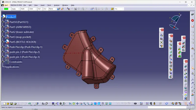
- With the help of assembly workbench we divided our input into 5 parts
STEP --2 (SOLID BODY )
A -DOOR ARM REST
Modification of the given master section
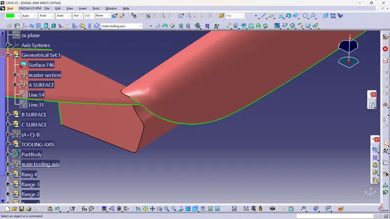
Given master section has a patch .First we want to improve the master section
After the improvement
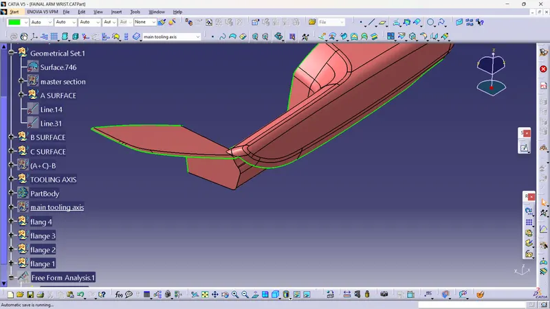
- Checking the continunity of class A
- Now offset the improved master section to for 2mm,because the master section showing that there is a cover above the arm rest
- so we have to offset the master sectio for 2mm.
- The below image is Class A surface of our door arm rest.
- We can clearly see its not proper surface, so we have improve it.
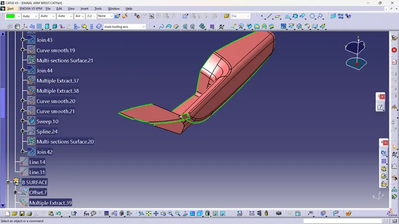
IMPROVEMENT OF CLASS A SURFACE
- Multi extract the surface which need to work
- Now use disassemble and divide this surface into 2 parts.
- Extrapolate the edge where we are getting problem of both surface and trim it
- Now multi extrapulate the class and select the above part and click complementary mode.
- join the trim and multi extract.
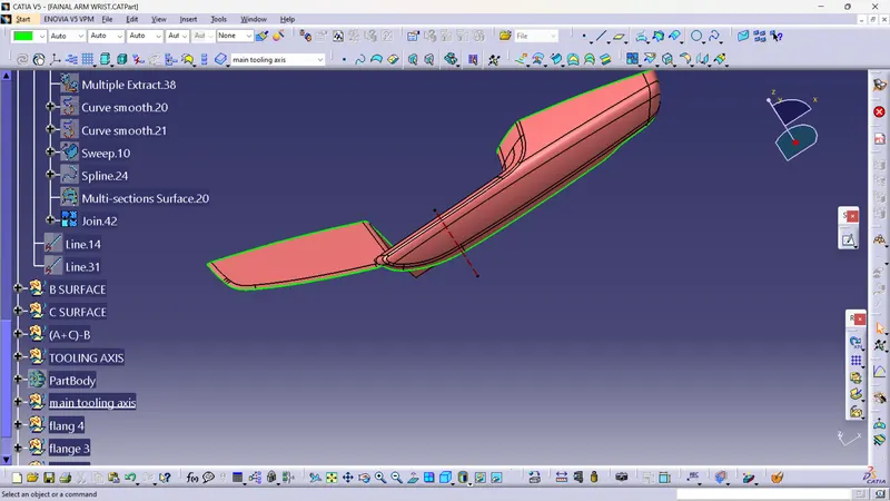
- There is a very small patch which is not proper as shown below image , we will cut it using split.
- In above i have used spline and extrude the spline and cut the using split.
- Now we have proper Class A surface.
2 - TOOLING AXIS
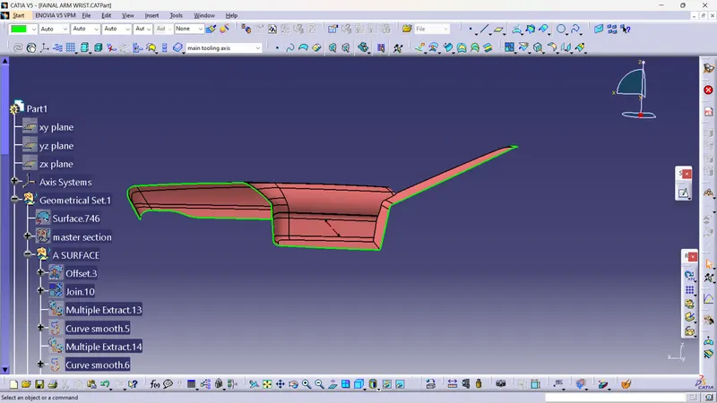
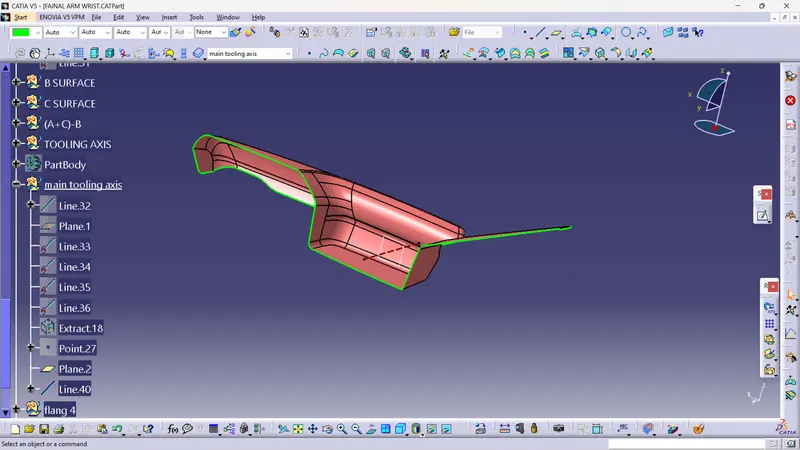
- Extract the surface of Class A surface and create a point on the surface.
- Now create a plane onthe surface .with the option of parallel the plane .
- Where the reference plane as ZX plane and reference point as the point created on the class A surface .
- Now we can see a plane in the surface
- And create a line with the option of normal to the surface ,where reference surface as the plane on the surface and reference point as the point created on the class A surface .
3 DRAFT ANALYSIS OF CLASS A SURFACE
- Click on Insert > Analysis > Features draft analysis
- Make sure it should be in material mode.
- Now go to direction, and click 2nd option.
- Pick the compass and align it with the tooling Axis and click on the lock .
- Now click on the class A surface.
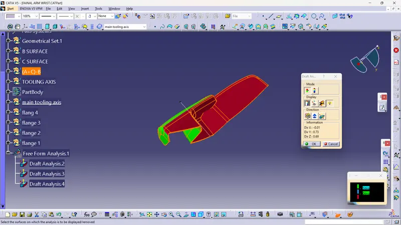
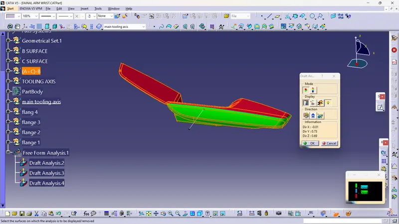
Here we can clearly see that Class A surface is not proper and it is not provided proper draft angle. So all face will be not clearing. Some face are blue because the class A bending inward.
As we know door arm will not be visible to people becuase it will have a cover above it so to solve this problem we can create two separate patch while moulding.
4 B-SURFACE CREATION
- Offset the class A 2.5mm in lower direction.
- We see some of the patchs are not proper as shown below image.
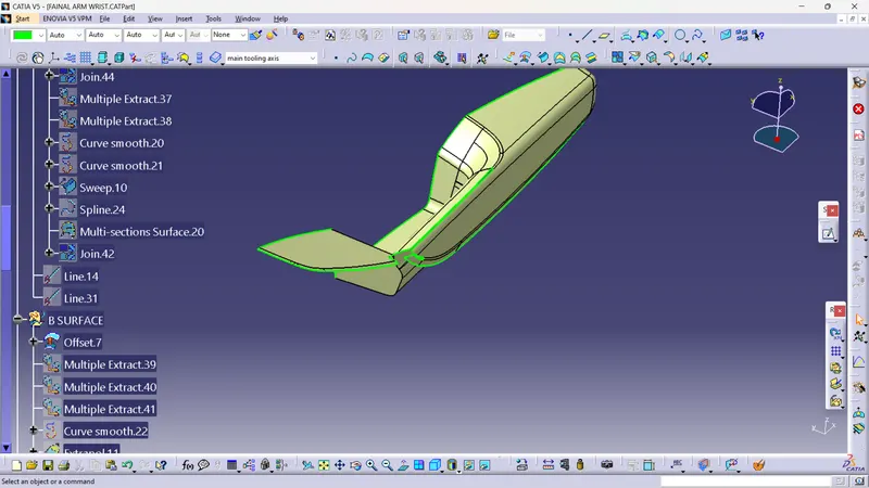
- Now I will work on the highlighted area.
- First I have tired extrapolate(1.2mm) and after extrapulate we will get surface.
- Now a have ectract a face.
- Now i have remove this highlighted portion, by drawing a line and extrude the line, and using split command.
- Below image shows result after split.
- Now we will join this split with offset.
- So first remove this face from offset using join or multi extract.
- So now i will extract the faces,which i have marked and extrapolate them.
- Now we split both of them and take cutting element opposite extrapolate .
- Now remove these part from above join using multi extract
- and then join both split and multi extract, as shown below
- We can see our corner part is solved but their is open patch inside.
- To solve this problem now we will using multi extract , i have remove this portion and also extract it.
- Also we can see a spline ,which i have made to cut the small portion.
- Use Disassemble and we will get 2 surfaces.
- Cut the small portion using split.
- now join split and 2nd surface and extrapulate
- Also using multi extract , extract the face as shown in the below image
- Now we will exrapulate this also(i have not extrapolated all edges)
- Trim both the extrapulate.
- Remove these parts from above join using multi extract.
- And join the trim and multi extract.
- So now we will work this green portion.
- since here it is overlapping, we will split that portion.
- Remove the face and extract the boundary .
- Now extrude the boundary.
- Also extract the other face and use split taking cutting element as extrude.
- Join them.
- Now we have solve all patch here.
- I have used Multi section surface.
- And join them and we will B surface.
- extrapolate the whole b surface for 1mm.
IMAGE OF B-SURFACE
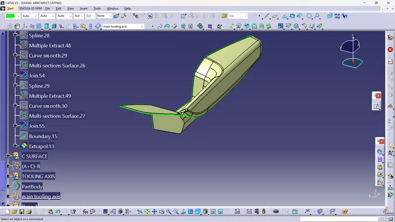
5 CREATING C-SURFACE
- I have used both sweep using draft direction and sweep using reference surface.
- In the remain area I have used multi selection surface.
- In the above pic to create a C- surface I have used sweep using draft direction taking angle as 3degree.
- Here i have used Sweep using reference surface.
- I was facing problem here , so i have cut some part of both C-surface using line and then i have used Multi selection surface.
- Now I will join all the C surface.
IMAGE OF C-SURFACE
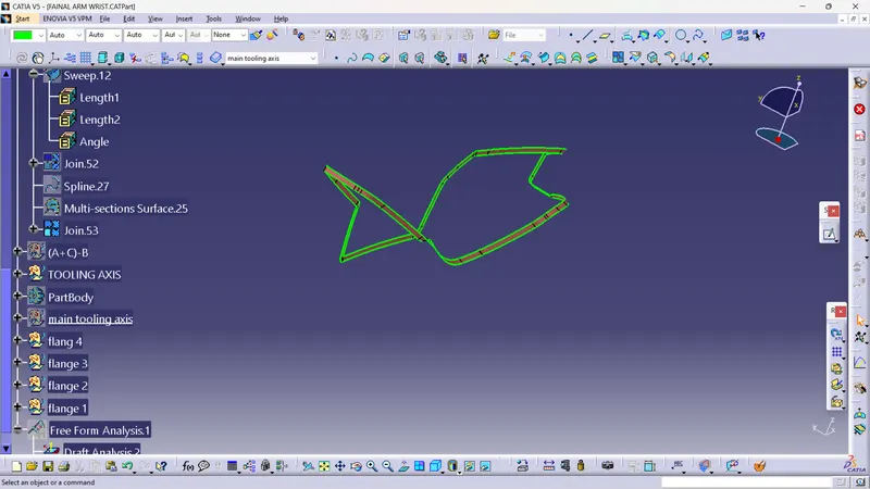
- Join C - Surface with Improve A surface.
- Now extrapolate Class B surface in some boundary and trim with above join.
IMAGE OF CLASS A+B+C
- Now from Part workbench , Make a solid part body using the close surface.
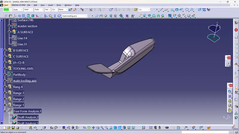
B- LOWER SUBSTRATE
We will check the connectivity of our class A surface using boundary command.Since their is no gap. We will move in next step.
1-TOOLING AXIS CREATION
- Extract the surface of Class A surface and create a point on the surface.
- Now create a plane onthe surface .with the option of parallel the plane .
- Where the reference plane as ZX plane and reference point as the point created on the class A surface .
- Now we can see a plane in the surface
- And create a line with the option of normal to the surface ,where reference surface as the plane on the surface and reference point as the point created on the class A surface .
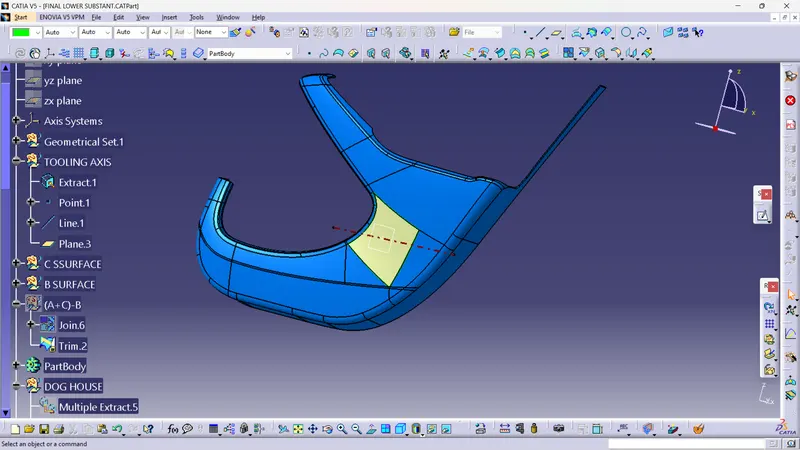
2- Draft analysis for CLASS A -Surface
- Click on Insert > Analysis > Features draft analysis
- Make sure it should be in material mode
- Now go to direction, and click 2nd option.
- Pick the compass and align it with the tooling Axis and click on the lock .
- Now click on the class A surface,we will see a green colour surface.
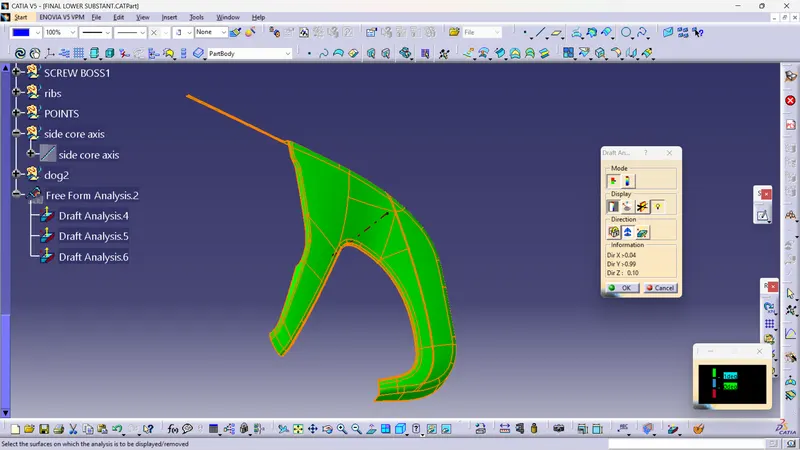
Since all face are green, it show class A is provided proper draft.
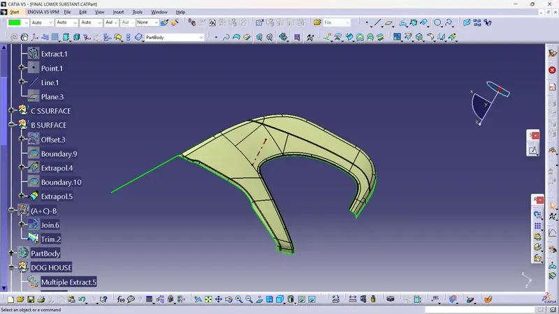
3 -- Creation of Class-B Surface
- Offset the class A 2.5 mm .
- No patches are there, so class B is made.
4 Class-C Surface
- To create C- surface I have used sweep using reference surface.
- Use boundary to extract the boundary of edges, and use sweep using reference.
- And in the corner, i have used Multi Section Surface.
- Now Join all the surface using Join and trim command.
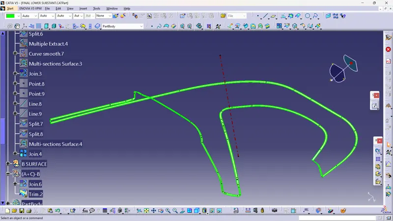
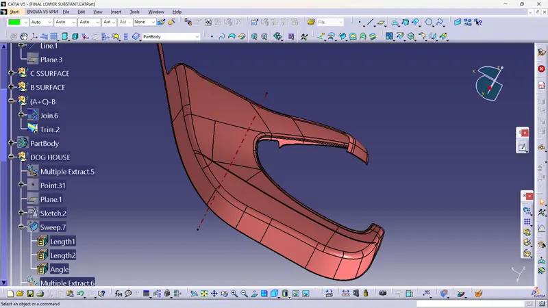
- Join the Class C- surface with Class A surface and trim with class B.
- We have received our final surface , now I have gone to part workbench and convert it into solid part..
C-MAP POCKET
We will check the connectivity of our class A surface using boundary command.Since their is no gap. We will move in the ext step.
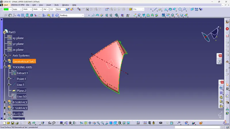
1-TOOLING AXIS CREATION
- Extract the surface of Class A surface and create a point on the surface.
- Now create a plane onthe surface .with the option of parallel the plane .
- Where the reference plane as ZX plane and reference point as the point created on the class A surface .
- Now we can see a plane in the surface
- And create a line with the option of normal to the surface ,where reference surface as the plane on the surface and reference point as the point created on the class A surface .
2- Draft analysis for CLASS A -Surface
- Click on Insert > Analysis > Features draft analysis
- Make sure it should be in material mode
- Now go to direction, and click 2nd option.
- Pick the compass and align it with the tooling Axis and click on the lock .
- Now click on the class A surface,we will see a green colour surface.
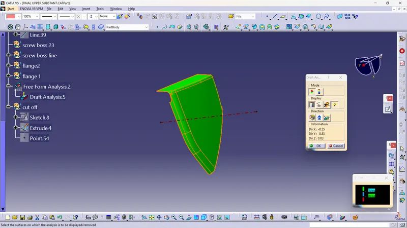
Since all face are green, it show class A is provided proper draft
3 -- Creation of Class-B Surface
- Offset the class A 2.5 mm .
- We can see that the corner fillet is missing.
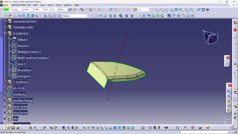
- Now using multi extract I have removed the fillets as shown in below image
- Usde disassemble command and we will get 3 surfaces.
- Now I will work on Pink surface ,draw a Line and extrude and use split to cut the unwanted portion as shown in the below image
- Extrapolate the split .
- Now extrapolate the middle portion and trim both the extapolate and apply the fillets.
- Now we will extrapolate the trim and remaining 1 surface.
- Trim them and apply the fillets we will get the Class B surface.
IMAGE OF CLASS B SURFACE
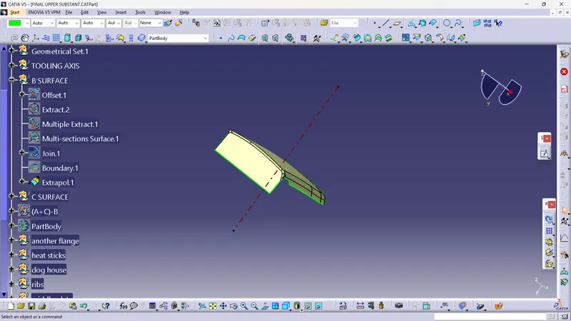
4 Class-C Surface
- To create C- surface I have used here both sweep using reference surface and draft direction.
- And in the corner, i have used Multi Section Surface.
- Use boundary to extract the boundary of edges, and use sweep using draft direction .
- Now remain area I have used sweep using reference surfac
- In the corner there was the surface was not so good ,so i have removed that patch and cut the c surface and filled using MSS.
- Join all the Surface and we will get C- surface.
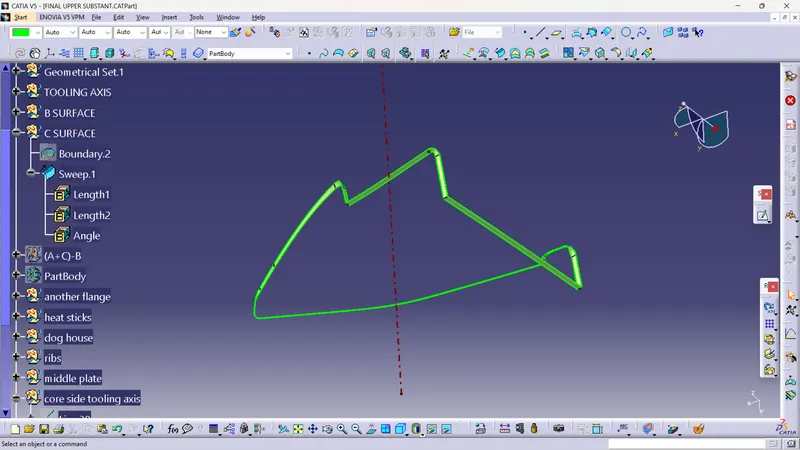
- Now Join with CLASS A surface and trim with class B.
- We have rreceived our final surface
- Go to part workbench and convert into solide part.
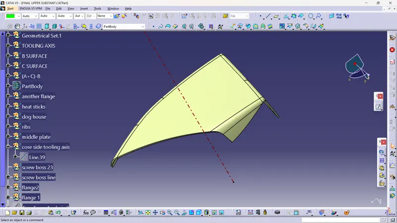
D-BOTTLE HOLDER
We will check the connectivity of our class A surface using boundary command.Since there is no gap, we will move in next step.
1-TOOLING AXIS CREATION
- Extract the surface of Class A surface and create a point on the surface.
- Now create a plane onthe surface .with the option of parallel the plane .
- Where the reference plane as ZX plane and reference point as the point created on the class A surface .
- Now we can see a plane in the surface
- And create a line with the option of normal to the surface ,where reference surface as the plane on the surface and reference point as the point created on the class A surface .
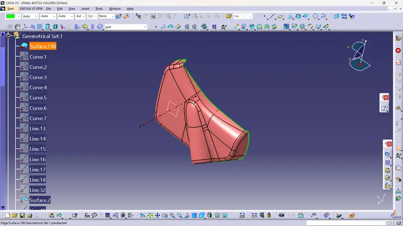
2-Draft analysis for CLASS A -Surface
- Click on Insert > Analysis > Features draft analysis
- Make sure it should be in material mode.
- Now go to direction, and click 2nd option.
- Pick the compass and align it with the tooling Axis and click on the lock .
- Now click on the class A surface.
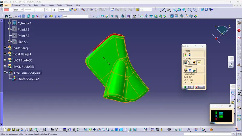
So here we can see some faces are not clearing draft analyis, this is happen because Class A is not given proper draft,if we look carefully the faces are inward. Also from normal view of our tooling Axis they are not visible,So Class A designer need to improve this surface.
4.B SURFACE CREATION
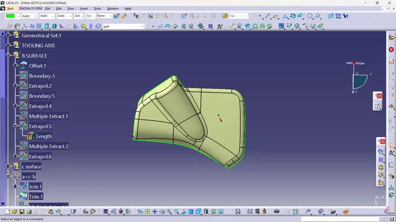
- Offset the class A 2.5mm outside.
- Since no the patches and fillets are missing so this will be our Class B surface.
4 Class-C Surface
- To create C- surface I have used sweep using reference surface.
- Use boundary to extract the boundary of edges, and use sweep using reference.
- Join all 3 sweep and this will be our Class C surface.
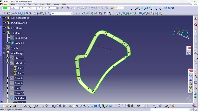
- Now join with Class A surface and trim with Class B.
- This trim is our final Surface.
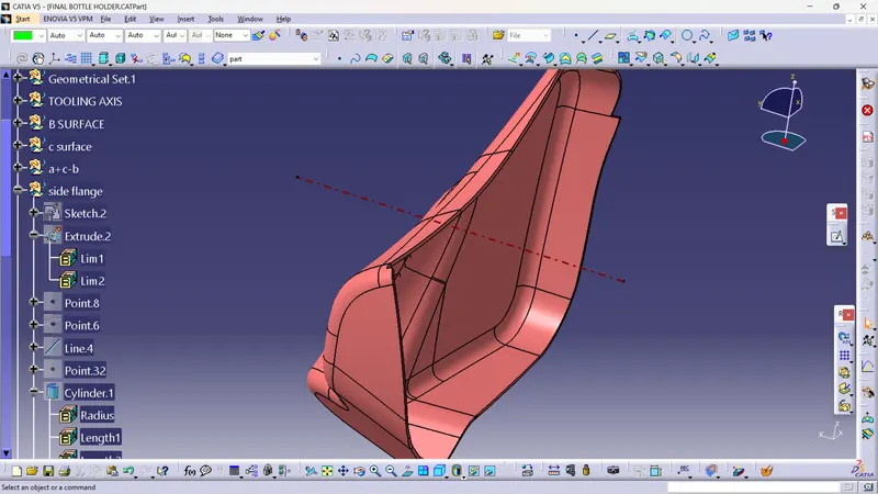
- From part workbench, make it solid by using close surface.
IMAGE OF CLASS A+B+C
STEP 3
N0W WE START TO CREATING ENGINEERING FEATURES
B- FEATURE IN LOWER SUBSTRATE - First I have made Heat Stakes.
HEAT STAKING - It is method of assembly , in which plastic (theromplastic polymer) stud or boss is heated and then cooled to assemble/lock with other components. In this the assembly will permanent.
Some of Advantages are
- Simplification of machinary
- Does not require extra parts for fixing
- Reduce cost,etc.
GENERAL DIMENSIONS
FOR HEAT STAKE
- Inner Diameter - 4.5 mm (From master section)
- Outer Diameter -7.5 mm(From master section)
- Draft angle- 0.5degree
- Height - 20 - 26 mm (may vary because of surface)
- Fillets- 0.25mm
FOR SUPPORTIVE RIBS
- Thickness of Rib- 1mm
- Height of Rib - 6 -10 mm
- Draft angle- 0.5 degree
- Fillets- 0.25mm
To make Heat staking we need to fellow following steps-
FOR 1ST HEAT STROKE
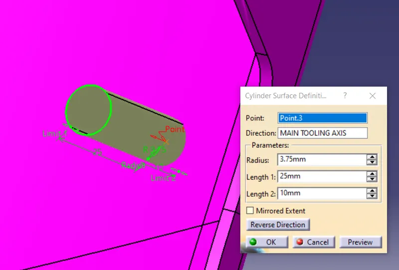
- I have made a point on surface on in Lower substrate.
- Now use cyclinder operation and take Radius as - 3.75mm and take direction as tooling axis.
- Now use ThickSurface and offset 1.5mm inward.
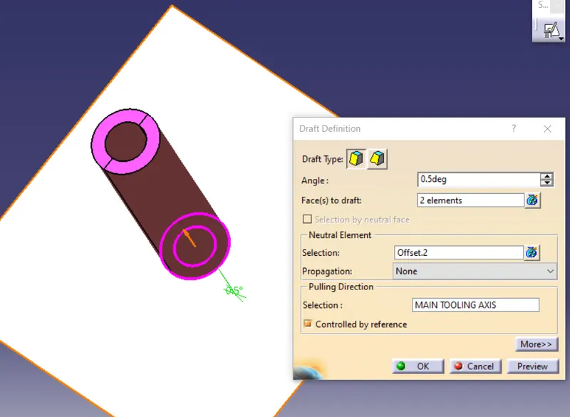
- Now this is our Heat stake , we need to provide the draft.
- For Netural element,I have made line on surface of part and extrude it in Z direction, and offset it 2 mm in down dirrection.
- Provide the draft as shown below
- Provie the fillets and our heat stake is ready.
- Now we provide the ribs for support.
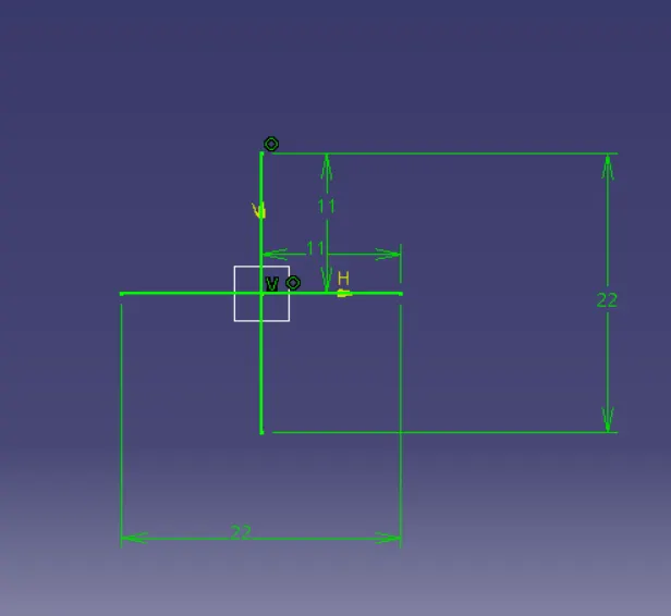
- Make a plan at that point and draw a sketch as shown below.
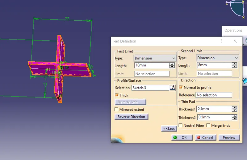
- Now we will pad it and thick on the thick options.
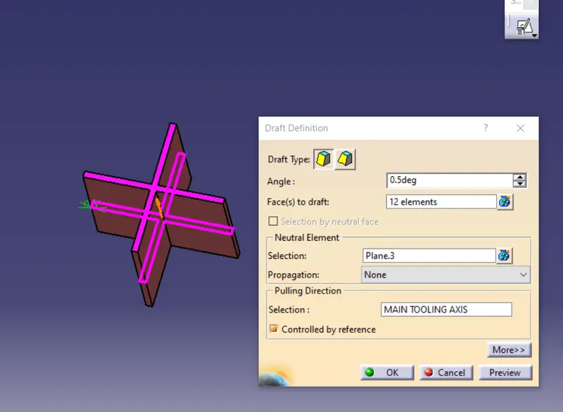
- Now provide the draft take the netural element as plane.
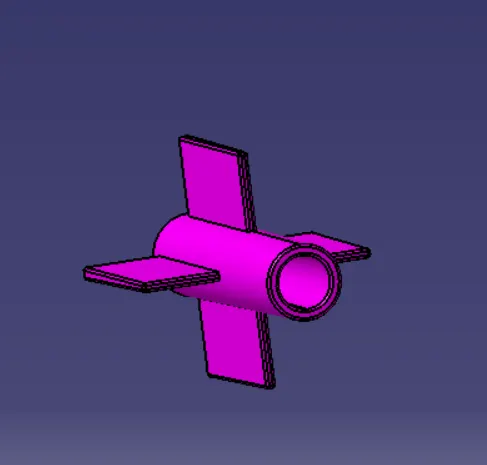
- Apply the fillets and use union trim with heat stake .
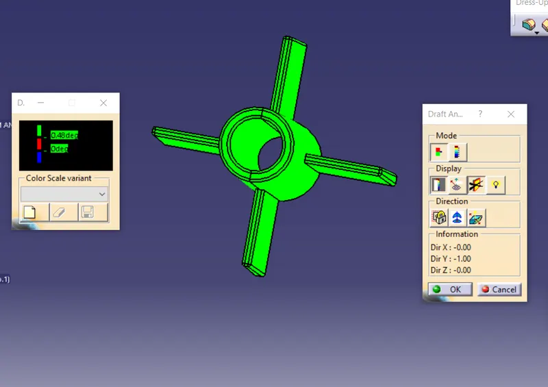
IMAGE OF HEAT STAKE AND SUPPORTIVE RIBS
HEAT STAKE FOR OTHER LOCATION
- Next step is to make heat stake at different location.
- So First I have made points at various location.
- Now I have copied the heat stake with rib body using paste special , I have created as much heat stake require.
- Now I have used translation, to make heat stake at various point.
- Now union trim this heat stroke with main body.
NOTE - I Have made a reference Axis on every heat stake to make hole
CREATION OF DOG HOUSE
DOG HOUSE- A dog house is a feature that is used
- to avoid sink marks
- solve length issue of screw boss
- and with the dog house we can make screw boss perpendicular to tooling axis
DIMENSIONS OF DOG HOUSE
- Draft angle for main tooling Axis= 1.5degree
- Draft angle for side Tooling Axis= 0.5degree
- C = 1mm(May vary because draft)
- B= 3 - 8mm from surface (Since our surface is not flat it will vary)
CONSTRUCTION
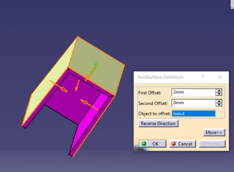
- First I have made a point at surface and made a plane normal to curve (tooling axis).
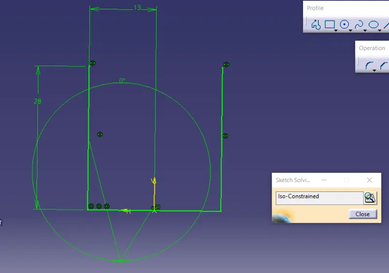
- Draw A sketch as shown below
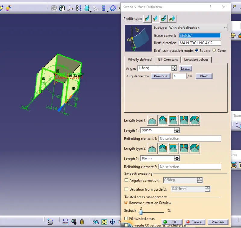
- Now sweep using draft direction and taking angle = 1.5 degree.
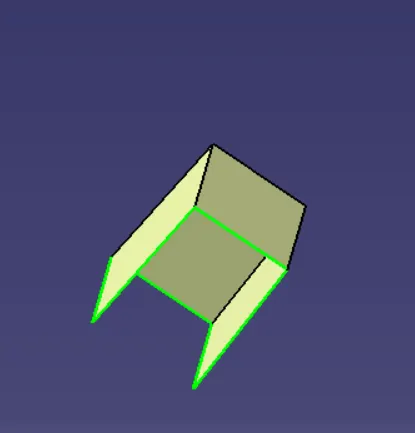
- Use multi section to cover above part.
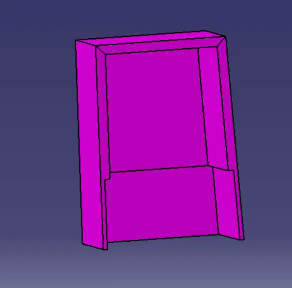
- Join them , we get basic shape.
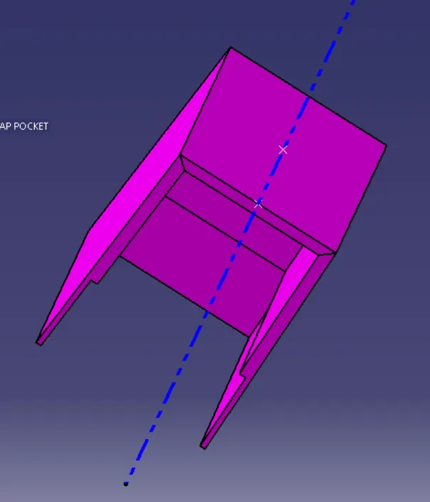
- Next step is to provide inside draft for side core.
- So first we make Side core axis.
- To create this a made 2 point in the top face dog house and both are in middle and make a line
- This line is our side core axis.
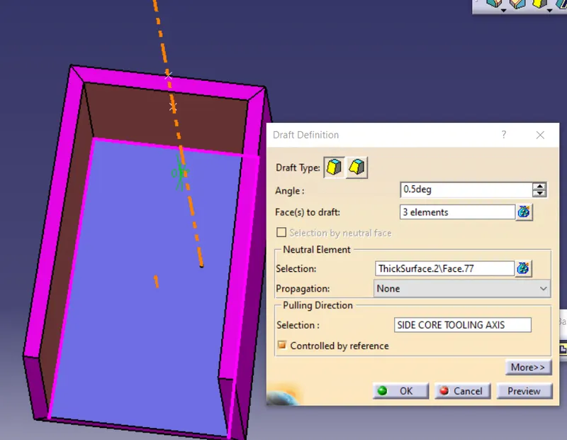
- Provide the inside draft .
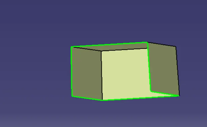
- Next step is to cut lower section.
- Extract the 3 walls and offset 1 mm inside and extrapolate this offset.
- Now extract top face and offset it 25mm and extrapolate it.
- Now trim both the extrapolate and using split from part workbench.
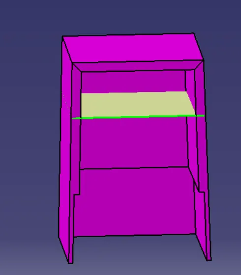
- Now i will make middle base and 2 supporting ribs.
- Offset top face extract 10.5mm and provide thickness of 2mm.
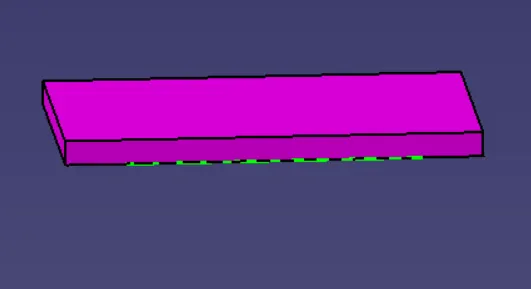
- Provide draft in side core direction of 0.5degree.
- Now i have made a line in centre
- extrude it and offset 5 mm both side. and provided the thickness of 1mm and prvide the draft in side core direction
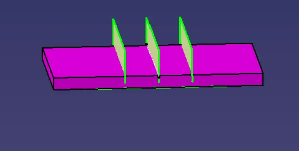
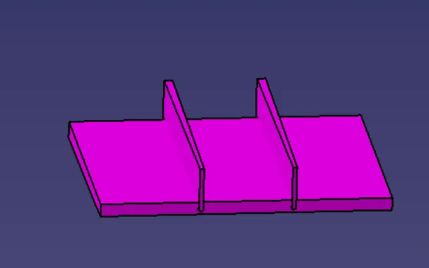
- Now i will union trim this with main dog.
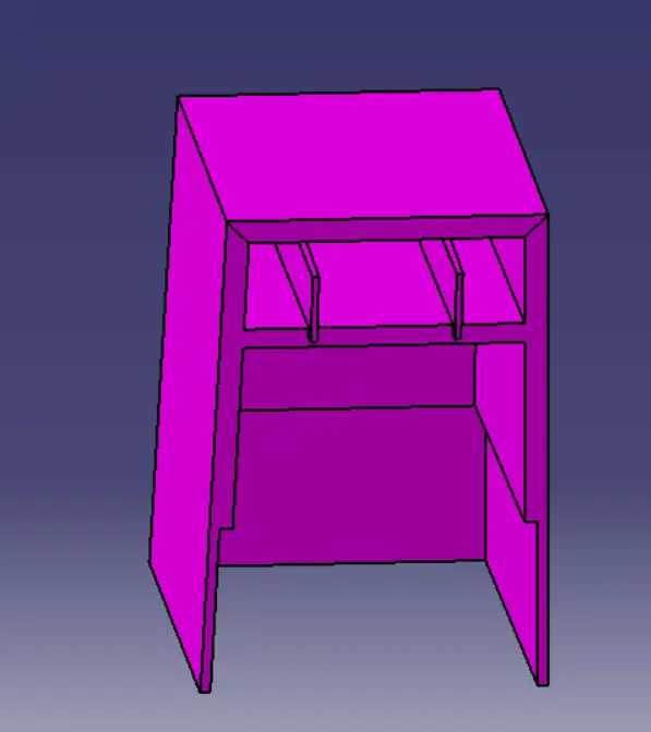
- The above surface is not proper so I have extrude back face and offset in front and split with dog house.
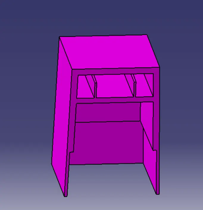
- Now we will makin top cut.
- Make a point in centre of surface and make a point on it.
- Draw a sketch as shown below.
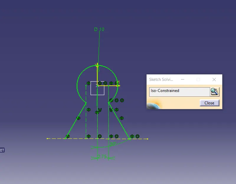
- Sweep it using draft direction and split it.
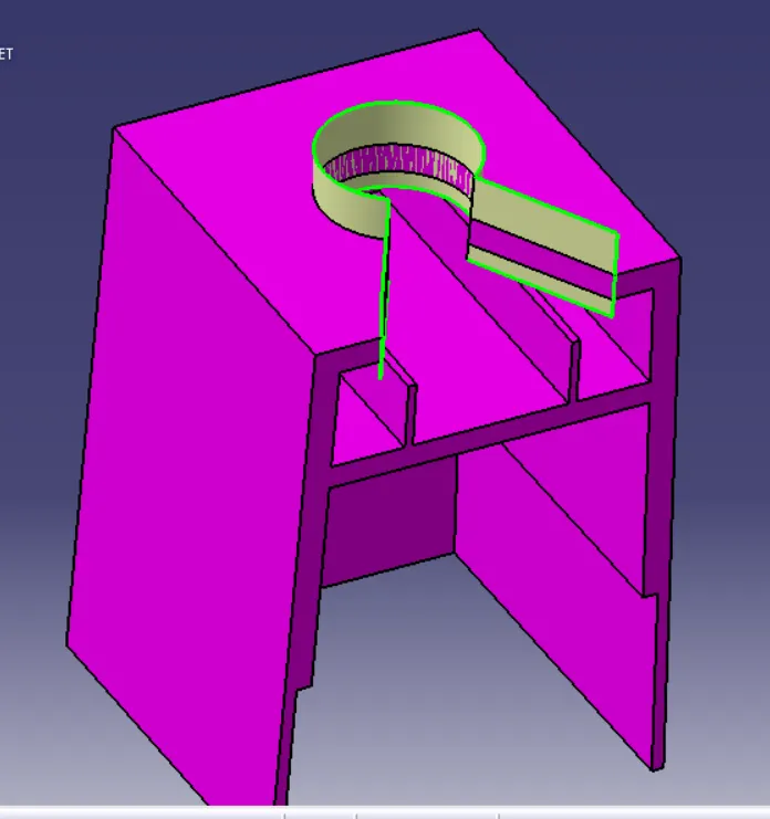
- Provide the fillets .
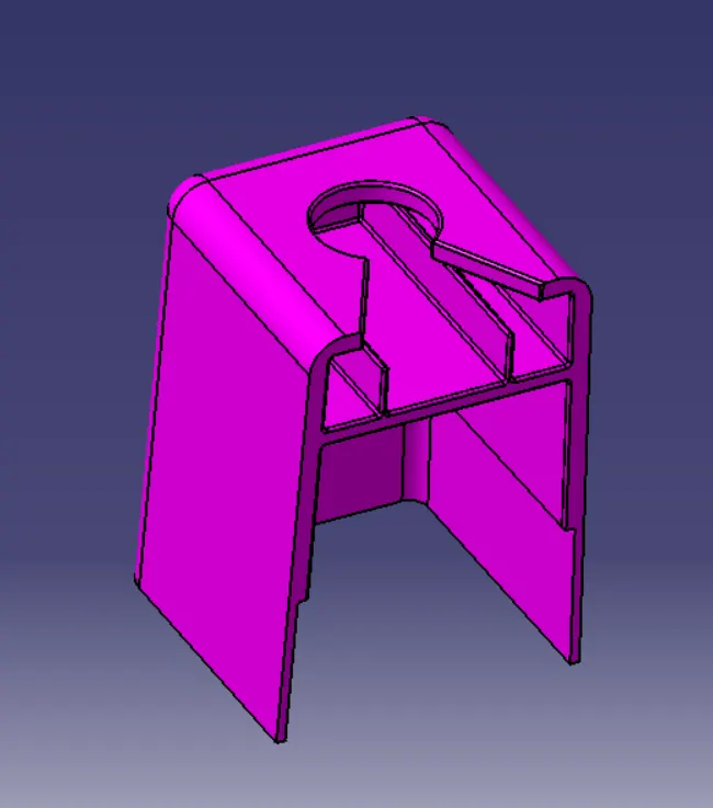
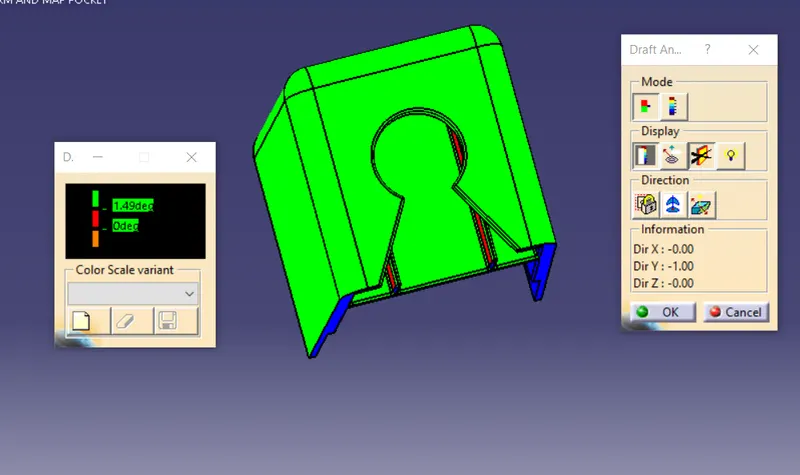
DRAFT ANALYSIS
MAIN TOOLING AXIS
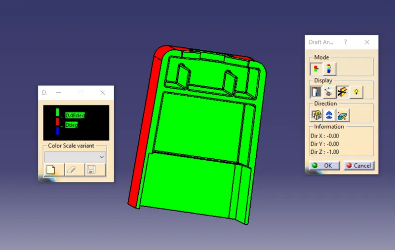
FOR SIDE CORE
- Now we will make dog house for other location.
- First I have point at 2 different points.
- Copy thr main dog house and used paste special.
- Now i have used traslation for position the dog house.
So we have obtain final part of LOWER SUBSTRATE
IMAGE OF LOWER SUBSTRATE
DRAFT ANALYSIS FOR LOWER SUBSTRATE
FOR MAIN TOOLIN AXIS
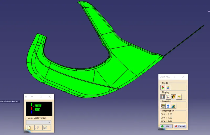
Since C surface is lower side so , it will be -ive and blue.We can see from normal view . Only very small portion is red shown in below image.
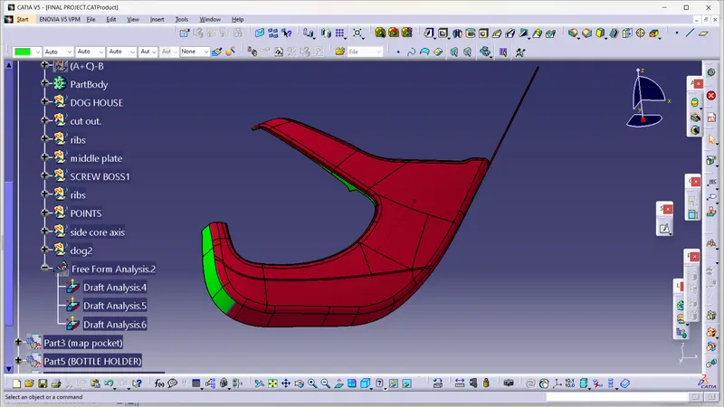
Draft analysis of DOG HOUSE
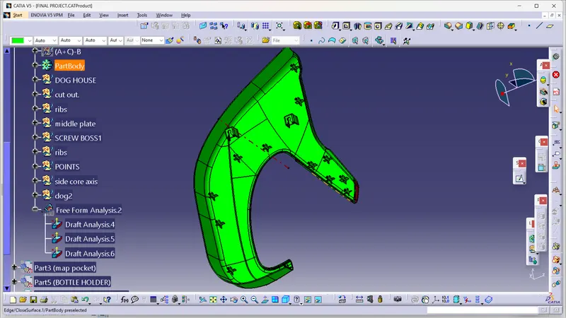
DOG HOUSE IS CLEARING IN MAIN DIRECTION
HEAT STAKE IS CLEARING IN MAIN DIRECTION
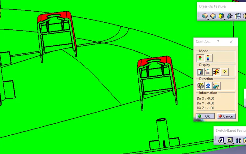
Dog House is clearing in side core direction.
B- FEATURE IN MAP POCKET
CREATION OF HEAT STAKE
Here Heat stake will use to join with bottle holder.So i have made 4 heat stake.
- Repeat same process for creating heat stake as I have done in lower substrate.
- And also for making other heat stake i have used translation feature.
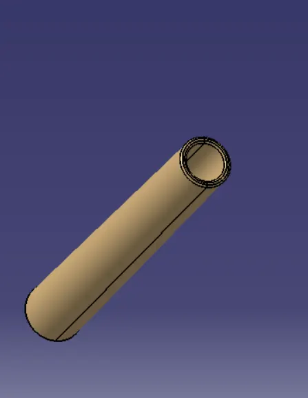
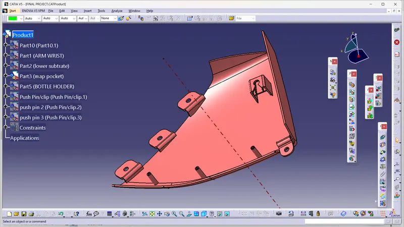
CREATION OF FLANGES
So the work of the flange will be to mate with heat stake and this will joint them permanently components.So we need flanges to connect lower substrate both the side.
- Using Master section I have extract the line as shown below
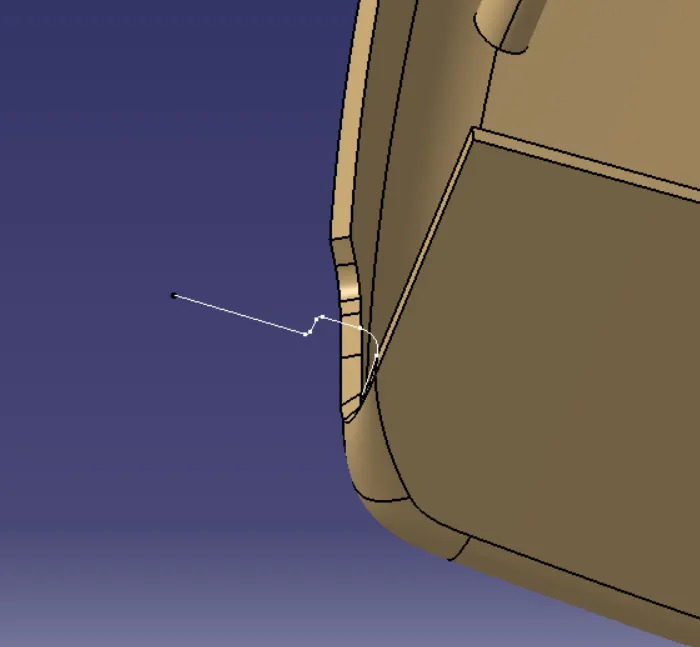
- Now with this extact I was not able provide thickness ,
- So I have a point and made a axis , and made a sketch.
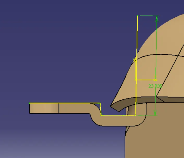
- now i have extrude it and provide the thickness of 2.5mm
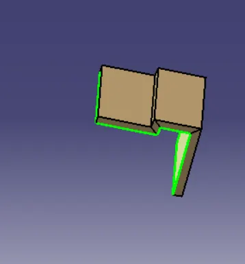
- Now i have provided the draft so that it will in main tooling axis
- Provide the fillets.
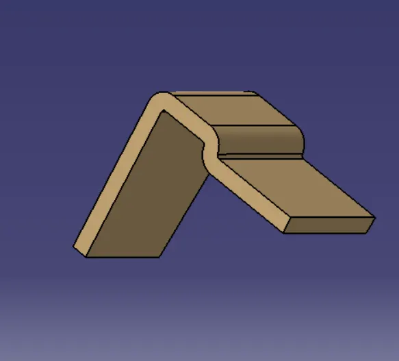
- Now we will provide the hole in the flange.
Providing the hole in the flange
- As i have drawn reference axis in heat stake, so with help of that will draw a circle.
- First make a point on surcface of rib anywhere.
- Now go circle and select the center and axis option
- Pick line as reference axis and pick the point make a circle diameter = 8.1 to 8.5mm(may vary).
- We will get circle on centre of reference axis.
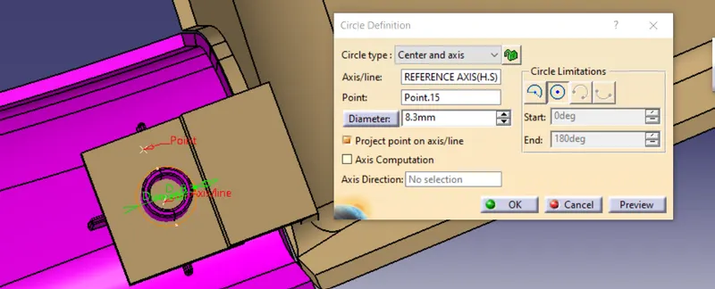
- Now will extrude it taking direction as tooling axis.
- Split it and we will get hole in flange.
- Now we will provide the draft inside the hole.
- After providing draft we have to check the cleariness of for hole.
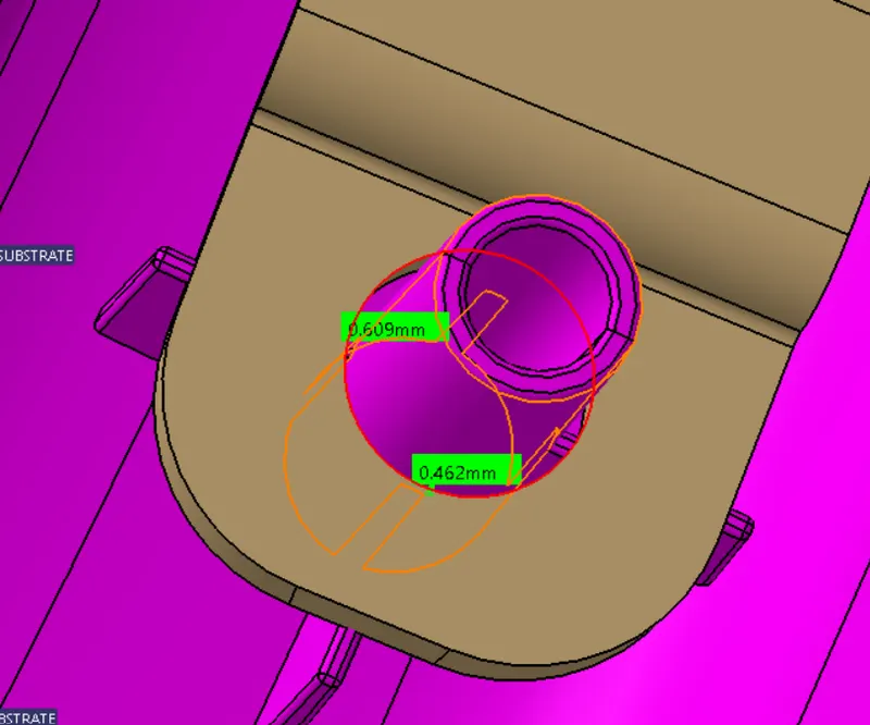
- So measure the distance and set the value of the above circle according to need of clearriness.
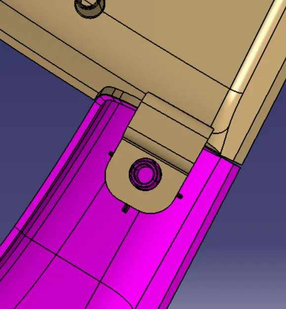
So in below image we can see the min distance is 0.47 to 0.6. It is varying because of draft.It will be different for different holes but it will between 0.48 to 0.58mm
Now we will create flange in other side of map pocket.
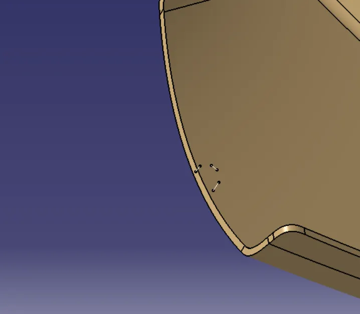
- Extract the lines from master section as shown below.
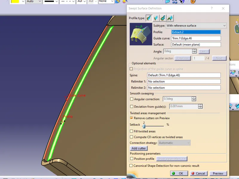
- Sweep them using reference surface
- Repeat same thing for other extract
- Now extrapolate every sweep
- And trim them
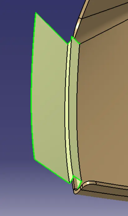
- Now make a line and extude it for direction I have made other line
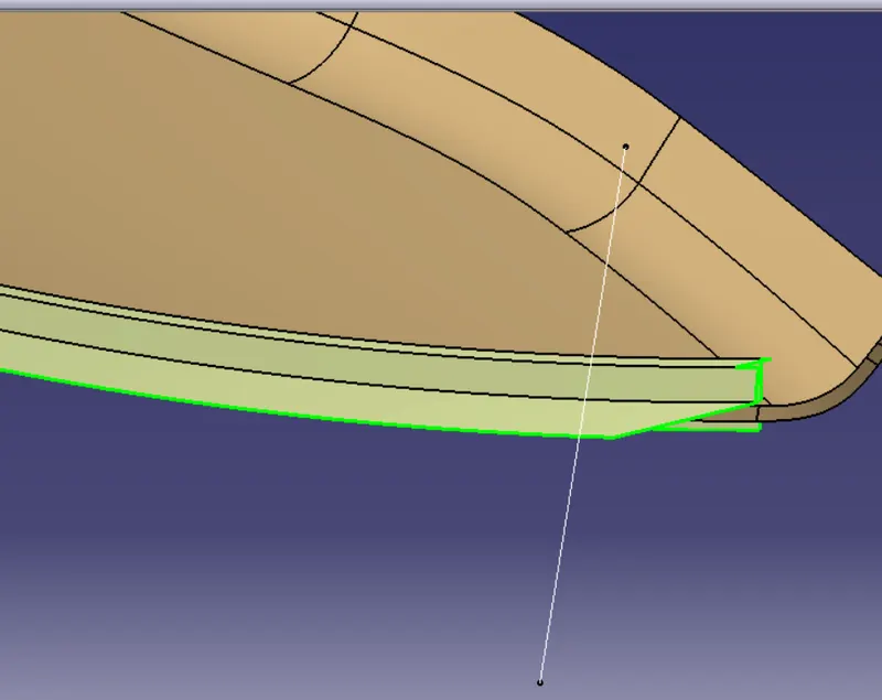
- So in below image the line is providing the direction to extrude.
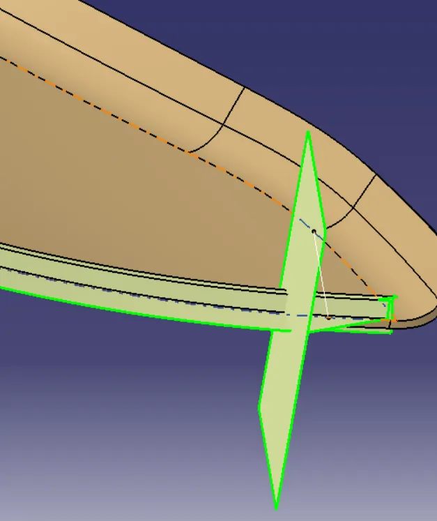
- Now offset this extrude 22mm.
- Now use split sweep (shown below)
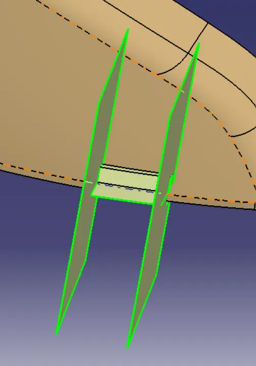
- Next is to provide the thickness to split.
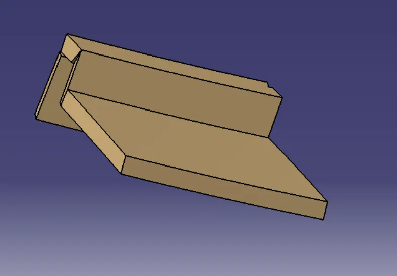
- In above pic , we can see the edges are not properly.
- So I have offset the above offset 1 mm inside from both side and split the above thickness.
Image after split
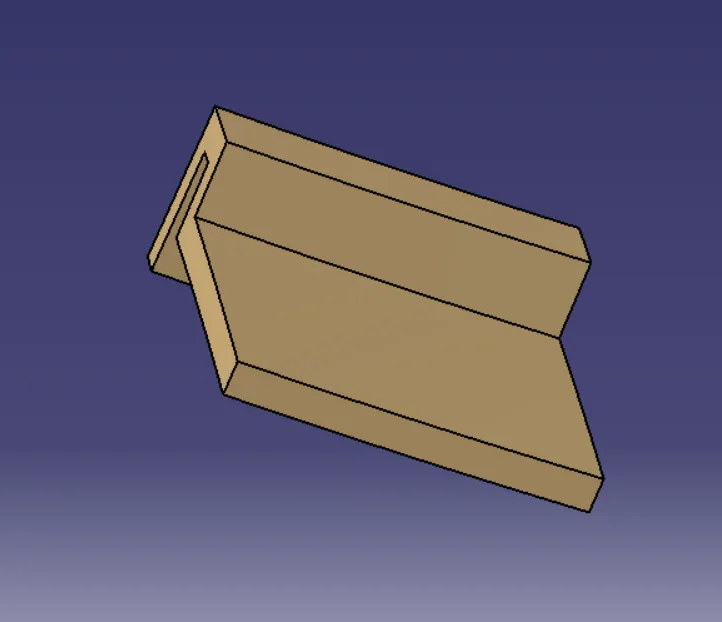
- Now I have notice the surface of flange was not clearing properly so i have provided the draft.
- Next step is make the hole.
- I have repeated same step to make hole as i done earlier.
- Provide the draft and fillets
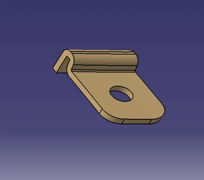
- For 3rd flange I use the traslation feature.
- Now unoin trim this with main part.
SO THE BELOW IMAGE IS FINAL OUR MAP POCKET
Draft analysis report for FINAL MAP POCKET
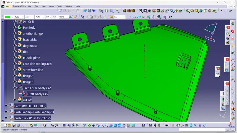
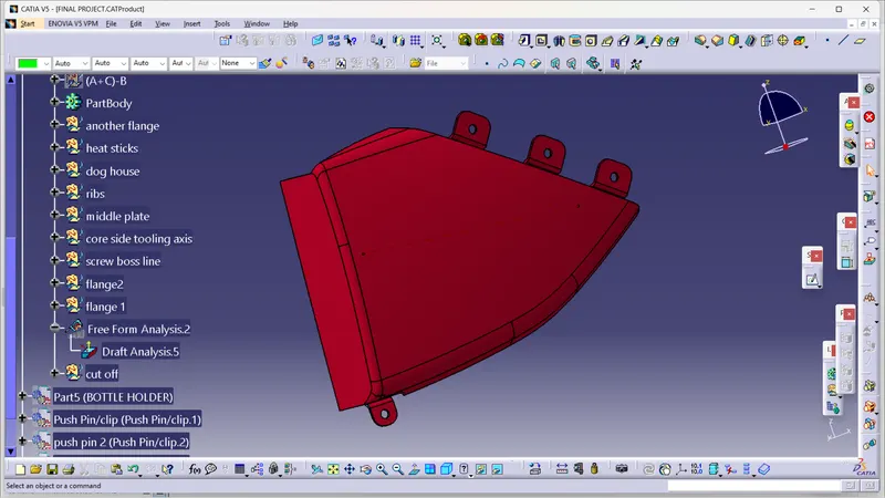
There are some small RED PORTION which is happening becuase our surface is not proper and our draft is changing from - ive to +ive.We will notice that the edges are going inward in 1st image.
B- FEATURE IN BOTTLE HOLDER
In bottle holder there will be FLanges which will mate with LOWER SUBSTRATE as well MAP POCkET.
FLANGES TO CONNECT MAP POCKET
- First think is to make a sketch, so I made a sketch as shown in below images
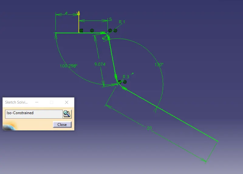
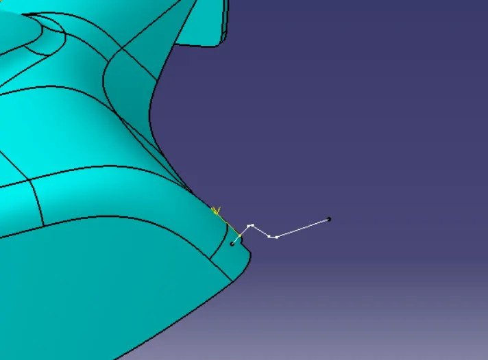
- Now i have repeat same step for creating previous flange
- Such i have first done split and and provided 2.5mm thinckness and made hole.
- Similarly for other side i am made another sketch
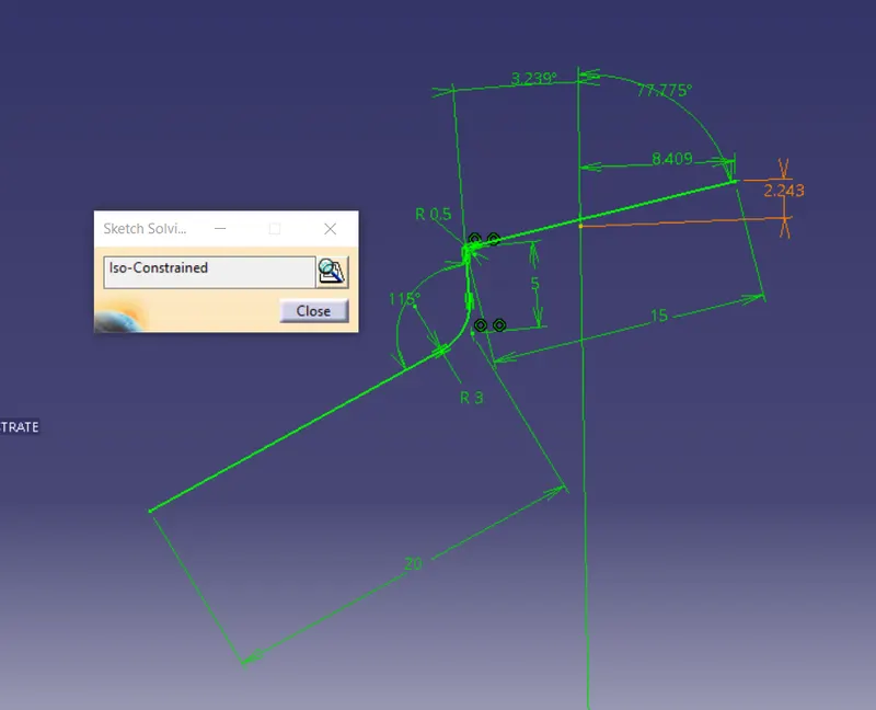
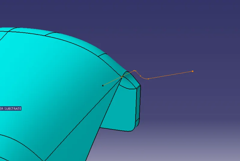
- Now i have repeated same step for creating previous flange
- Such i have first done split and and provided 2.5mm thinckness and made hole .
- And for 3rd and 4th flange I have used translation feature.
- Now i union trim with main body.
- And the cleariness is 0.5mm.
FLANGES TO CONNECT LOWER SUBSTRATE
- I have made 7 flanges to connect the lower substrate.
- With help of 3 sketch I was able to create all 7 flanges.
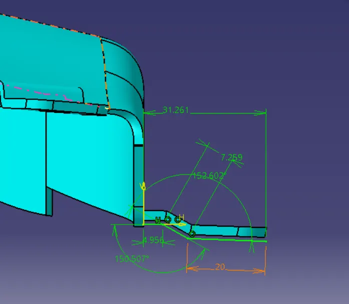
Above image is sketch for the 1 st flange .
- After making sketch I have extrude it and offset 1mm upside, so that it not come below the egfes of surface.
- Now i have thicken it and make the holes and apply the draft.
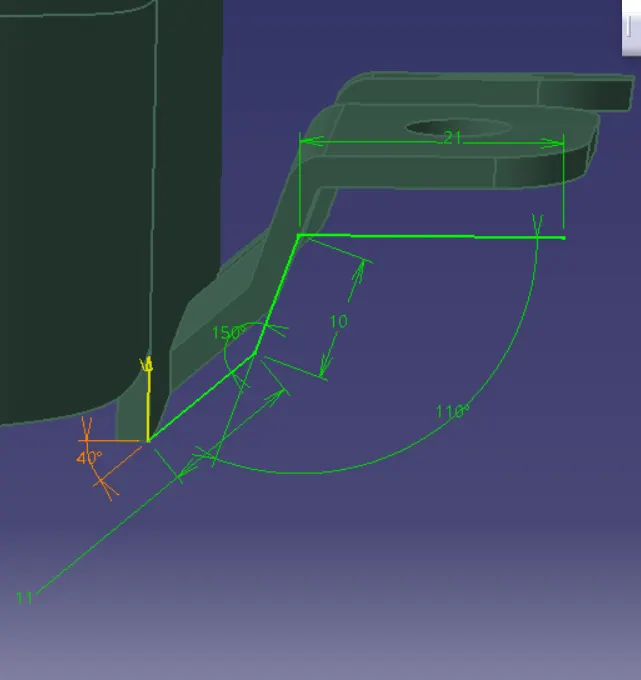
Above image is sketch for the next 4 flanges.
- After making sketch i have used multi-extract and extracted the boundary in the lower egdes.
- Now I have used sweep using reference surface.
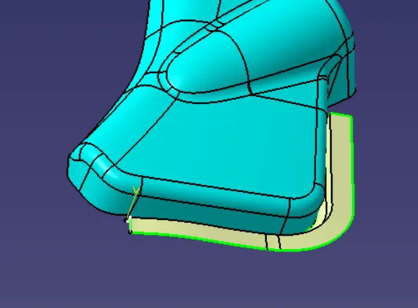
- Now i have split it into 4 separate patches and thickned them and repeat same step for creating previous flanges.
- And for last 2 flangesi have a sketch but i done sweep 2 time in opposite direction as shown below.
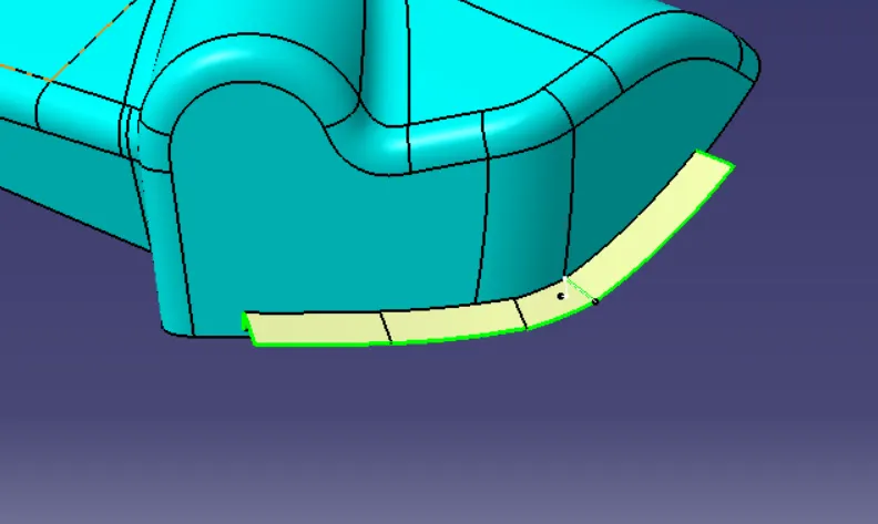
- Now i split and repeated same steps for creating flanges.
- Now union trim with main body.
IMAGE OF FINAL BOTTLE HOLDER
CLEARNIESS IS WITH 0.5MM
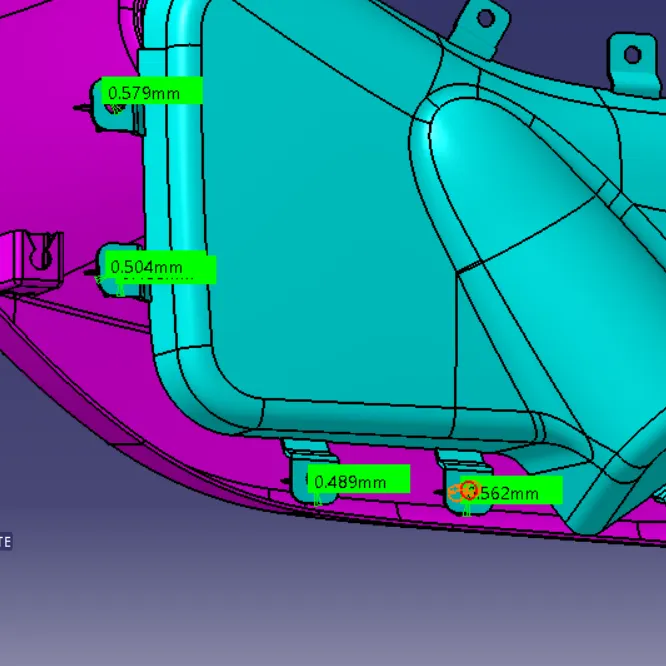
Draft Analysis of the final Bottle Holder
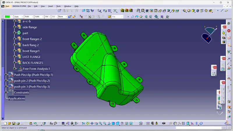
In above pic there are some area where our class A is blue, this is happening because class A was not given proper draft so it is not possible to clear it. To clear it we need to work on class A surface, and than the remaining area will be clear.
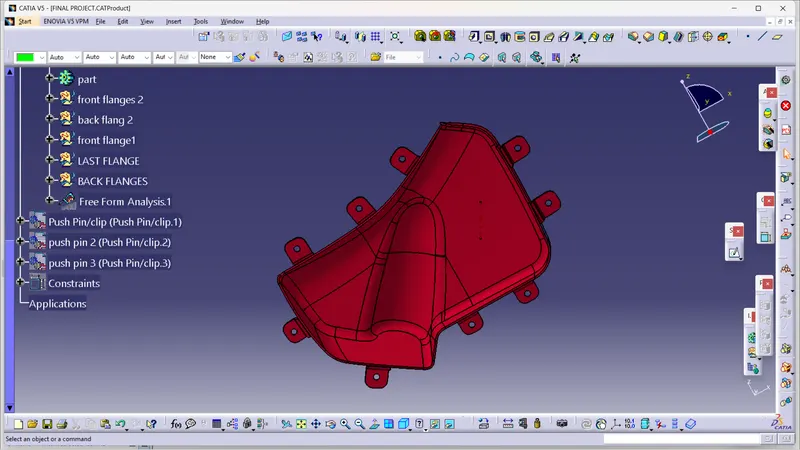
All flanges with holes are clearing in draft analysis.
B- FEATURE IN ARM REST
- In arm rest I have made 4 flanges to with lower substrate
- 1st two i have made with the help of master section
- I have extract the master section using multi extract and used sweep.
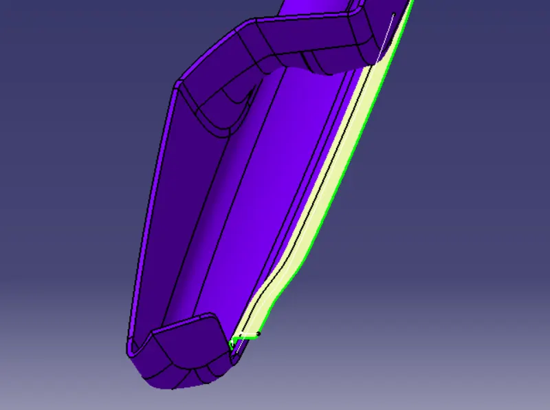
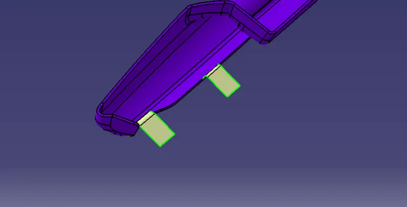
- After sweep I have used split and thickned the splits.
- Provided draft and fillest and holes as per requirement.
- For last 2 flange I have made a sketch
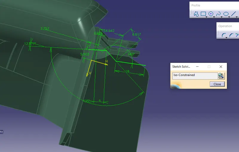
- now i have sweep the sketch and split it.
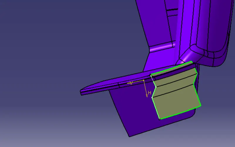
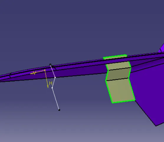
- Repeat the same step as earlier to provide the thickness and hole.
- Now using union trim to join with main body
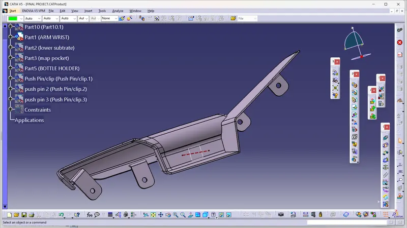
IMAGE OF FINAL DOOR TRIM
Draft Analysis for the final Door Arm rest
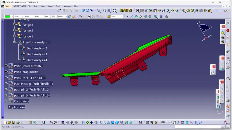
FROM MAIN TOOLING AXIS
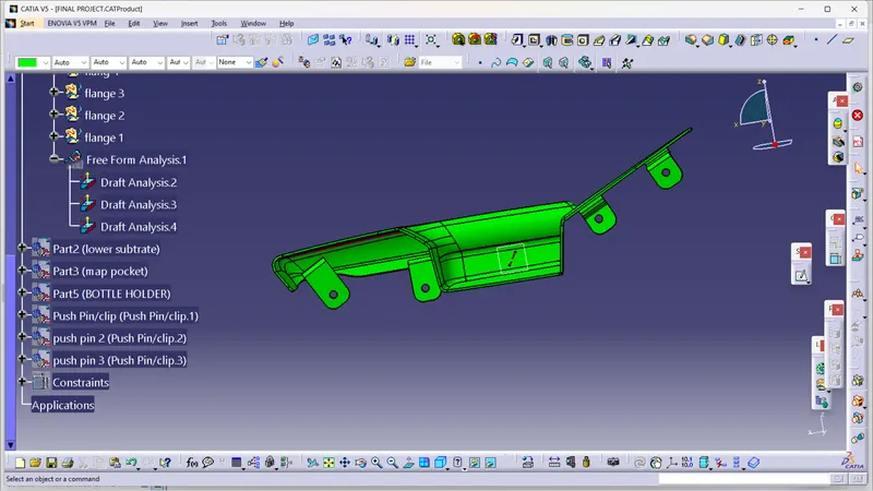
Since our class A is not proper, So some of faces are not clearing with main tooling axis, so we need to side core to clear reamining area.
All the remaining faces are clearing with main tooling axis.
ASSEMBLY