Week 11 - Final project
SOl-Development of the door trim using CATIA from the given class A and master section and performing draft analysis part along with the creation of B side attachment features.
THEORIES & CONCEPT-
RIBS- Rib features help in strengthening the molded part without adding to wall thickness.
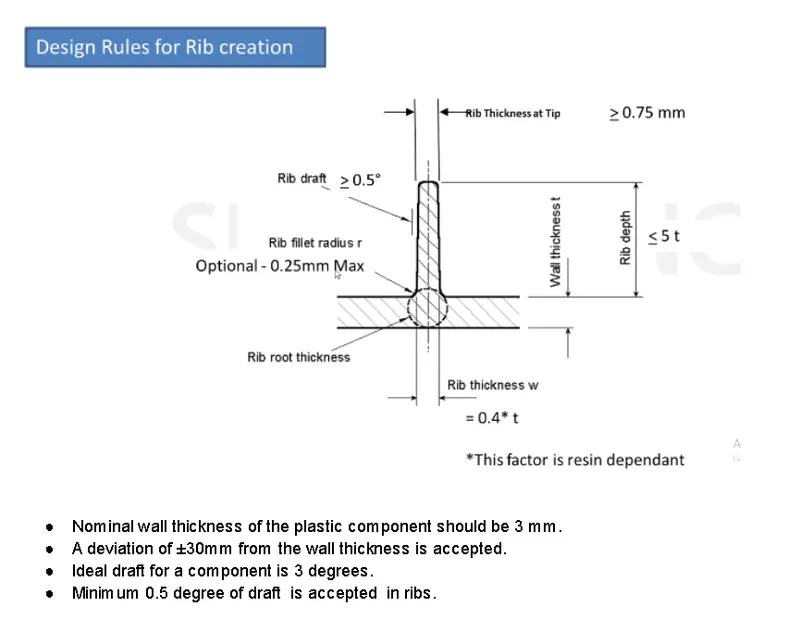
rib intersections, the resulting thickness will be more than the thickness of each rib. Coring or some other means of removing material should be used to thin down the walls to avoid excessive sinking on the opposite side. The height of the rib should be limited to less than 3 x thickness. It is better to have multiple ribs to increase the bending stiffness than one high rib.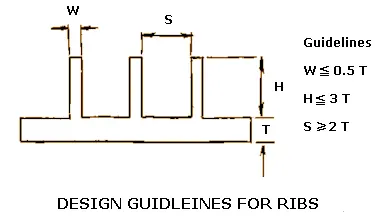 Draft angles for ribs should be a minimum of 0.25 to 0.5 degrees of draft per side.
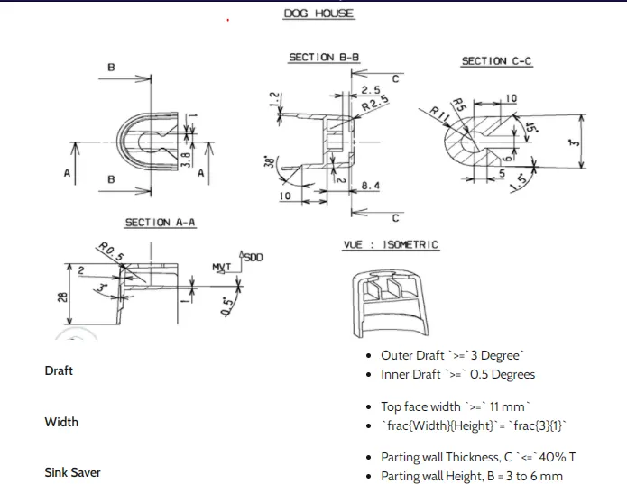
Dog House- Dog houses are used as supporting features. Sometimes other engineering features like snaps; locators, etc. are mounded on them to increase their strength.
Flange- Flanges are also a supporting feature like dog house heat stakes etc.
In our Door trim development, we have to create a B surface & C Surface, Door assembly is divided into 4 parts lower subtract, an armrest map pocket, and a Bottle holder.
MATERIALS- The right plastic for an injection molded product must conform to both part and production restrictions and requirements. Additional factors include application specifications, aesthetic considerations, industry standards and regulations, and material recyclability or permanence. The most common plastics are,
ABS: An easily molded, rigid, strong material with high impact and temperature resistance.
NYLON-A general-use nylon, nylon 6/6 promises high wear resistance and can be used to make parts via both molding and extrusion processes. It’s favored for its strength, low cost, and stability, and it’s commonly found in weatherproof coatings.
- Polyurethane.
- Polyvinyl chloride
- Polycarbonate
- Polyethylene
- Polyoxymethylene etc
Why is plastic used in the automotive industry and many industries?
Today, automotive designers are looking for a lightweight material that will improve the design, manufacturing, and efficiency of molded parts. For decades, they replaced heavy metal components with plastics such as polypropylene (thermoplastic)
Increasing plastic in the automotive industry helps to reduce weight and increase fuel efficiency. Design freedom, new, bolder, and more functional aesthetics, greater safety, reduced weight and thus fuel consumption, commitment to sustainable development … This is how plastics are revolutionizing the automotive industry.
here are mainly 4 factors to consider while choosing a material for a component.
- LIGHT WEIGHT- Being lightweight can improve fuel efficiency more than other factors. If we replace the high-weight product with a lower density without reducing rigidity and durability.
ECONOMIC EFFECTIVENESS- Economic effectiveness plays a vital role in choosing a material for the automotive industry. It determines that any new material has the opportunity to be selected for a vehicle component. cost includes three components.
a.Actual cost of raw material
b.Manufacturing value added
c.Cost of design and & testing the product
RECYCLING- In the European Union and Asian countries there are some guidelines on this subject. Many OEMs are using recycled plastic for housing & manufacturing other products. It will also help to reduce plastic wastage
SAFETY- Safety on of the major concern at present.
In the Thermoplastic process also products are made through the liquid molding process, the polymers and other agents are fed into tanks or hoppers, where they are heated to a liquid state and mixed. Then the liquid polymers and other agents are injected into a mold cavity but the only difference is that here screwed are tapered and the cavity is cold.
There are several manufacturing processes like
a.Injection molding
b.Vaccum forming /Thermoforming
c.Blow molding
d.Rotational molding
e.Extrusion
f. Structural foam
g.RIM (Reaction injection molding)
Door panel- Door panels serve as an interface between the interior of the car and the inner workings of the door, and between vehicle occupants and the door. They are expected to meet a variety of design specifications regarding safety, aesthetics, and functionality.
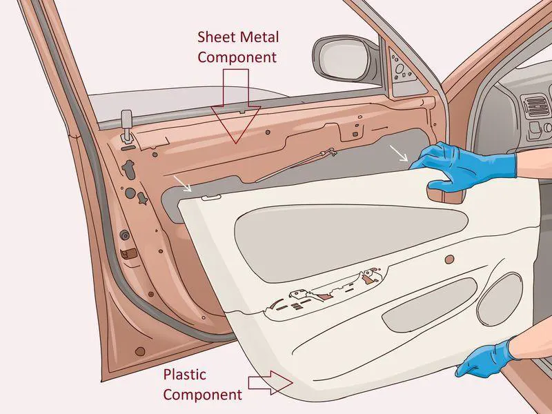
OBJECTIVE-
1. To create thickened parts using the master section for reference.
2. To create a mounting feature as per design requirements design and master section.
3. To perform draft analysis.
BOTTLE HOLDER- The bottle holder is a part of The Door Assembly
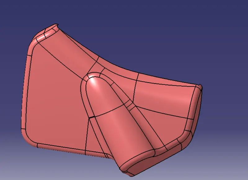
SURFACE A- The surface is given by Styling engineers.
Surface B- Surface B is a surface where we can make changes and also B features that help for joining with another component.
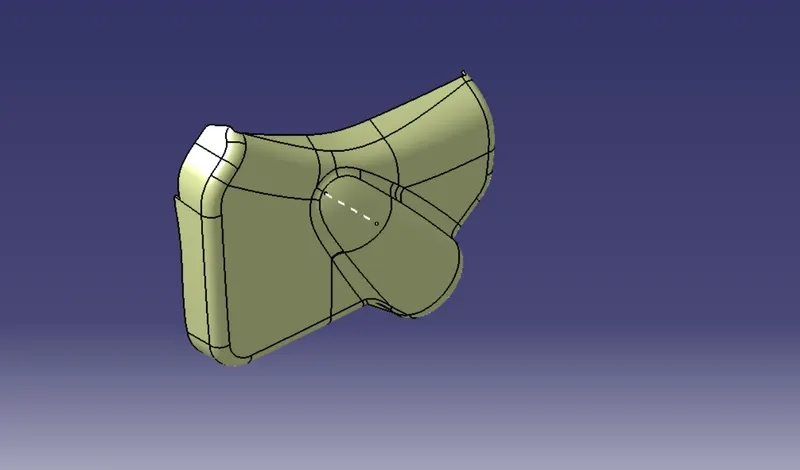
Surface C - Surface C is used to join both surface A and Surface B, after that we get our final product
while creating surface B we used some commands like
Offset, MSS, Extrapolate, Trim, and join commands, for surface C we used the sweep option.
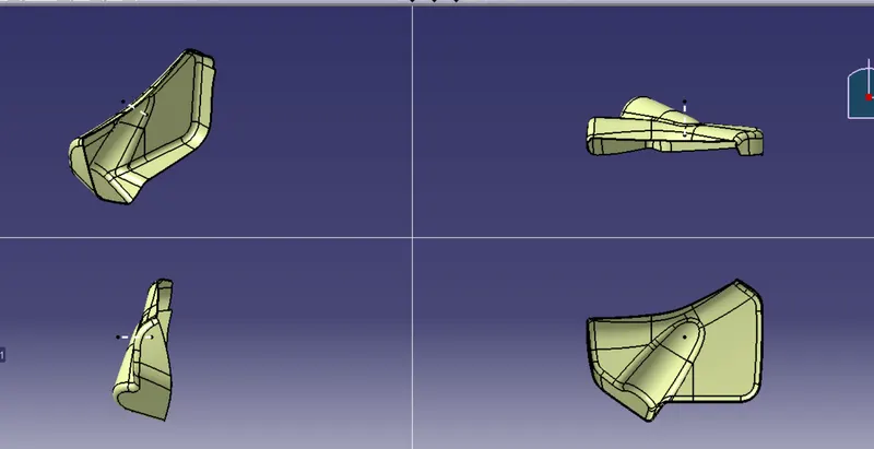
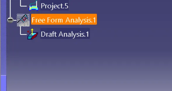
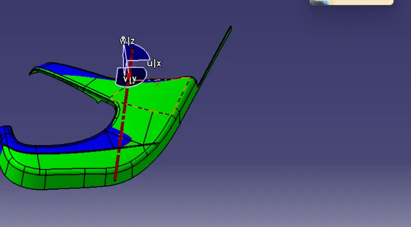
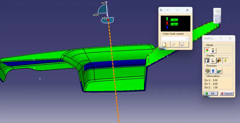
Draft analysis- The draft analysis technique is used to analyze whether our part model created in CAD is manufacturable based on the draft condition applied. Here the part should get easily removed from the Mold
The Draft Analysis allows the user to easily analyze a part for a proper draft angle.
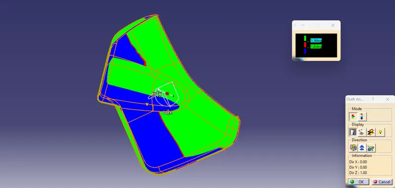
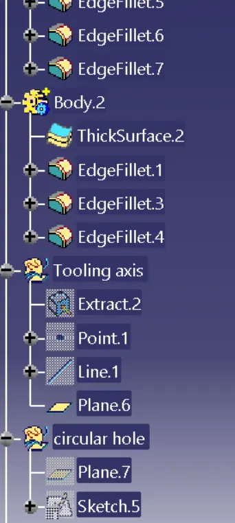
Tooling axis - We can create a tooling axis by using
1. Using point and direction
2. by using the bisecting method.
In this we extract surface and take a point on the surface and use point to direction method for tooling axis
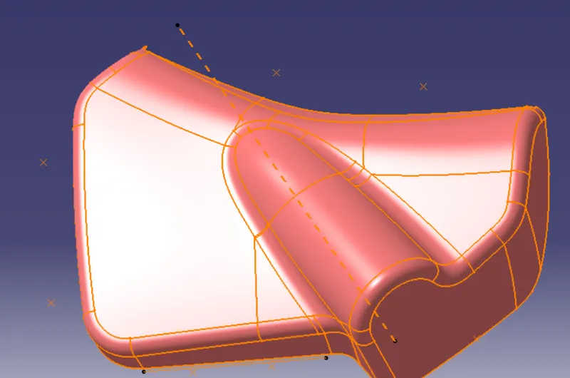
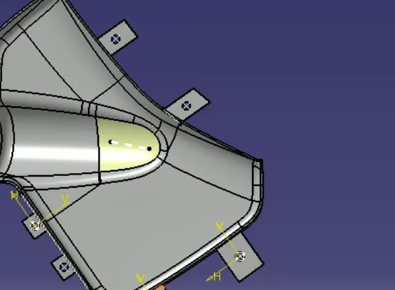
After that joining or trimming A+C with B surface, we get the closed body ( part in front, top side, iso)after that using the closed body command we get our final product
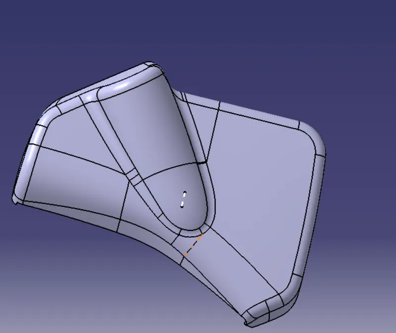
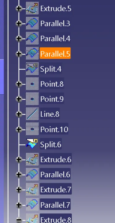
Procedure- While creating the body we used different steps given below
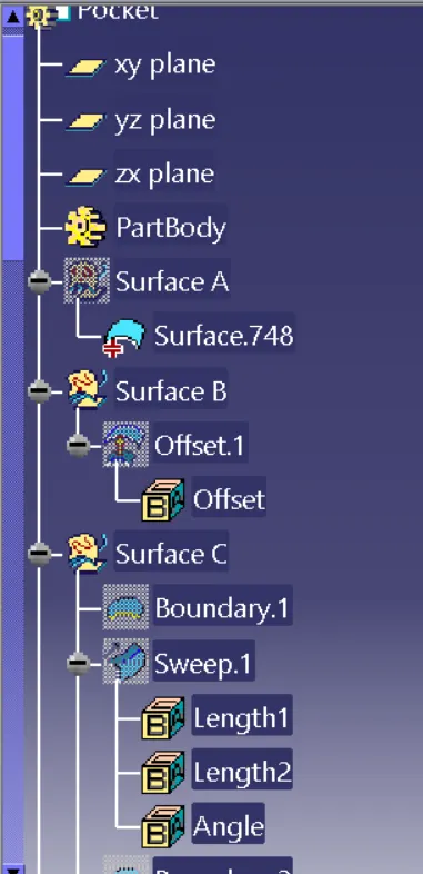
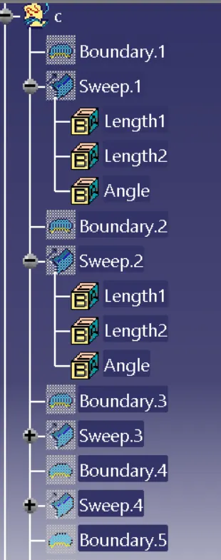
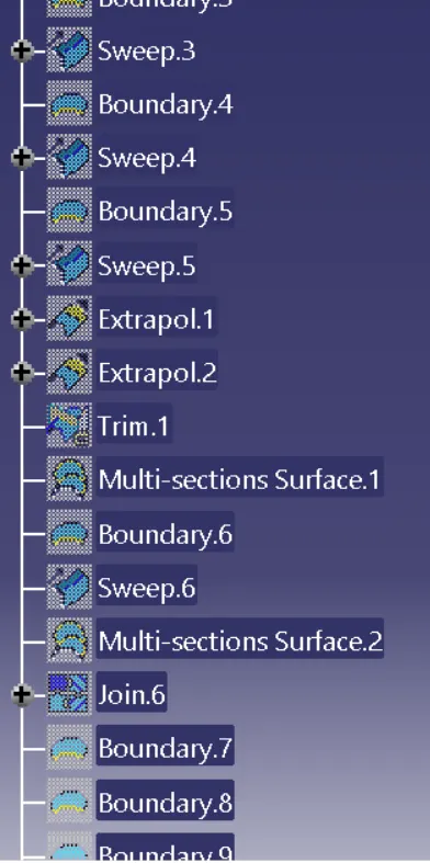
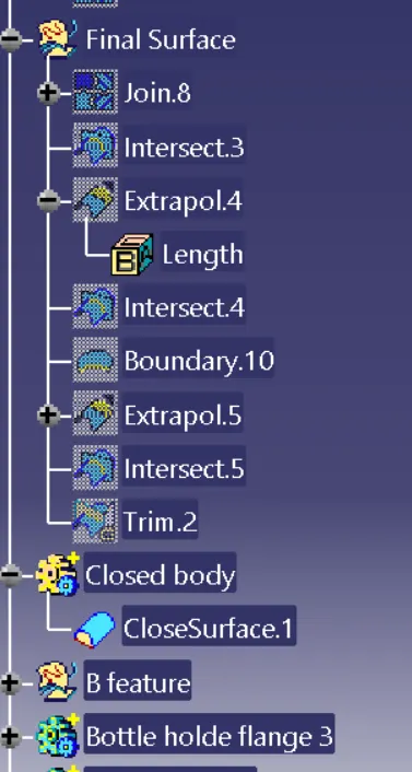
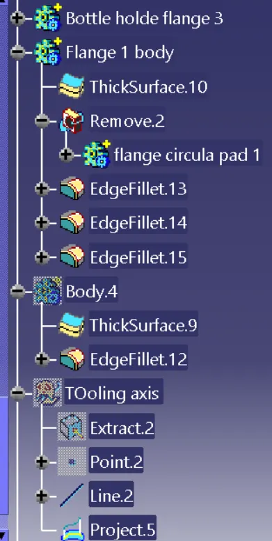
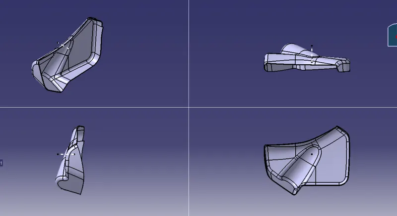
A different view of the body
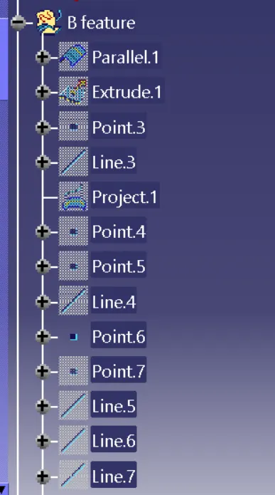
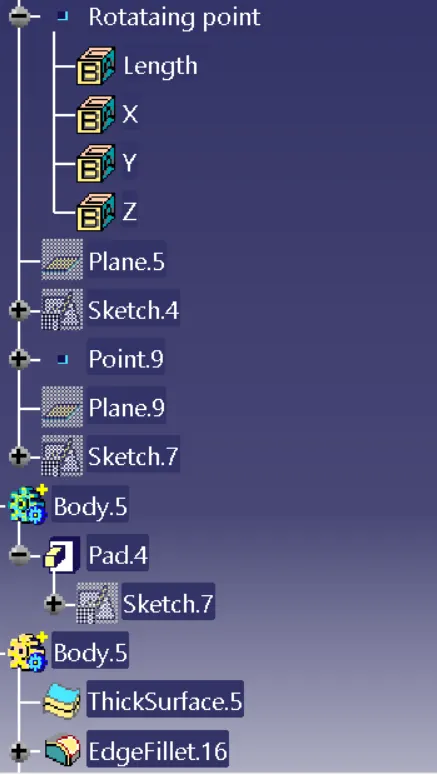
Part with Flanges and procedure
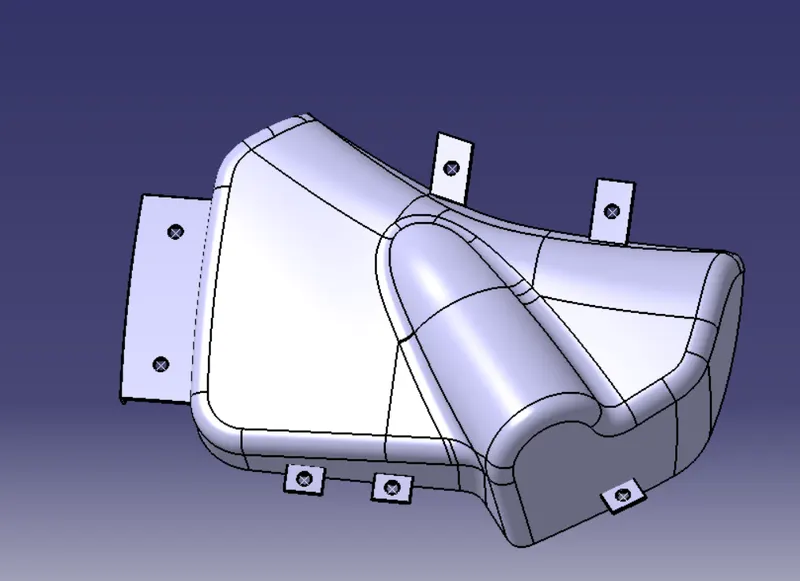
Lower subtract( Door Panel)- The door panel styling surface has been given by engineers.
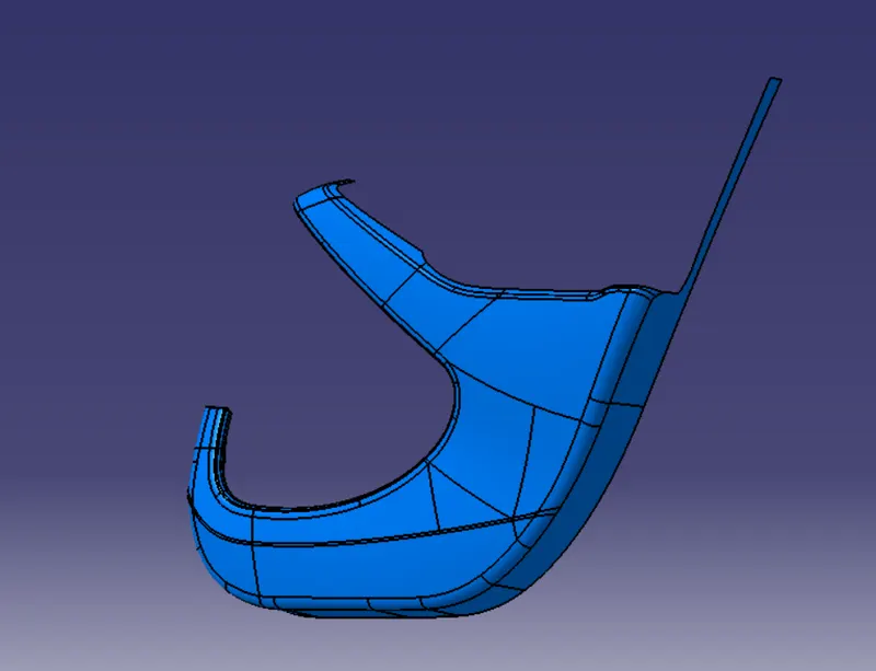
SURFACE B- Surface B is a surface where we can make changes and also B features that help for joining with another component.
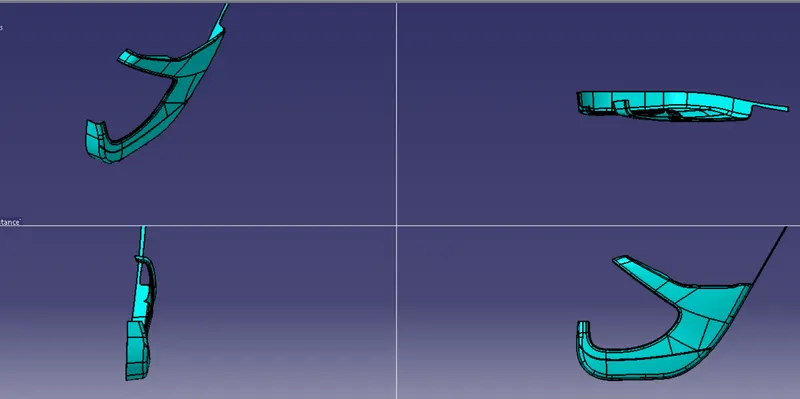
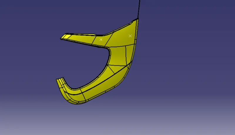
Surface C - Surface C is used to join surface A & Surface B
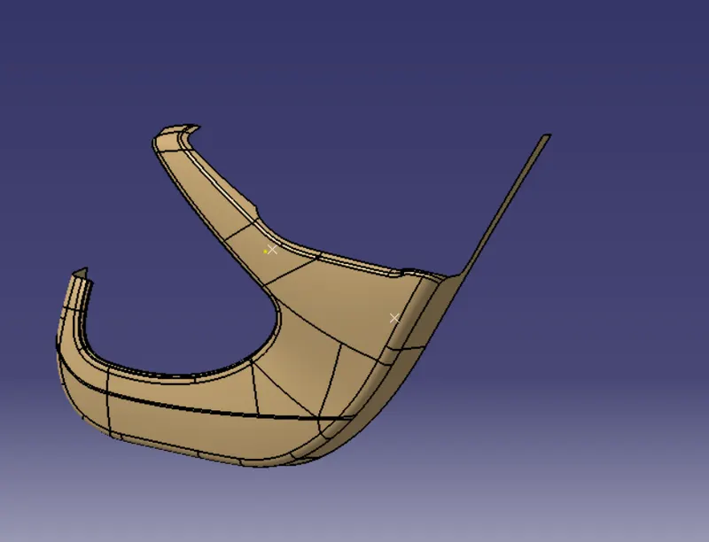 +
+ 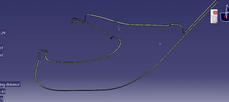 =
= 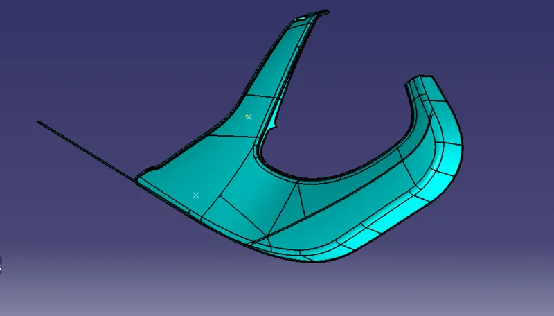
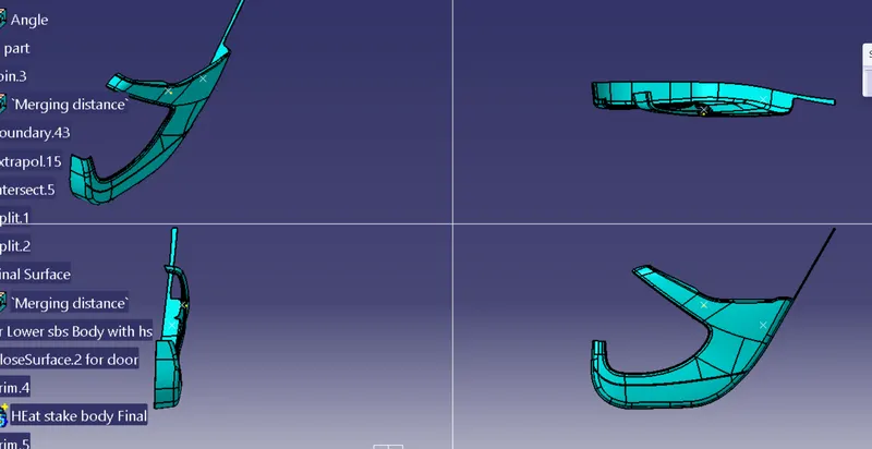
after that we get closed body
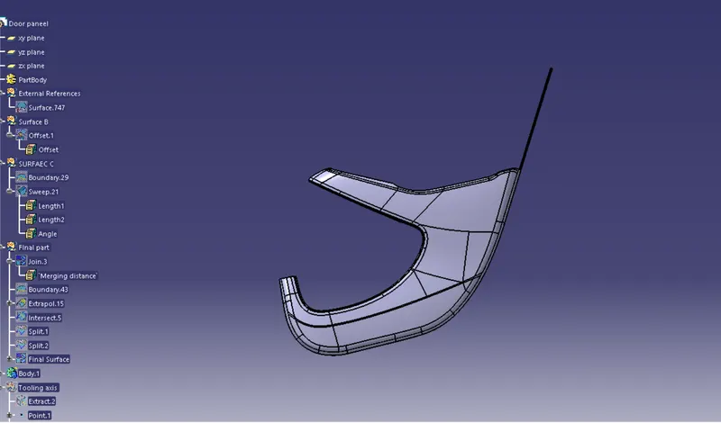
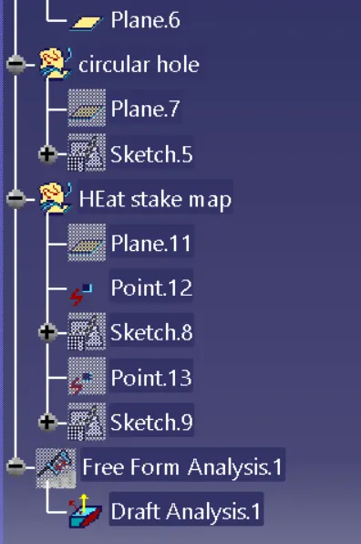
Draft anyalsis & Tooling axis
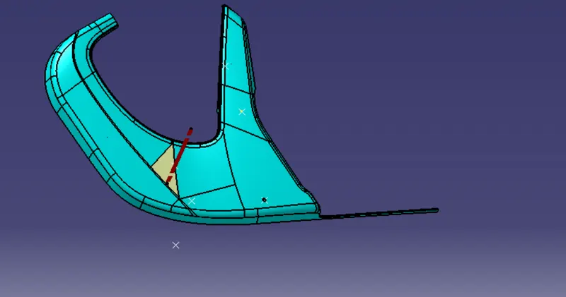
Procedure- While creating the body we used different steps given below & heat stakes.
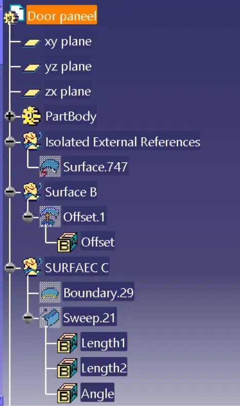
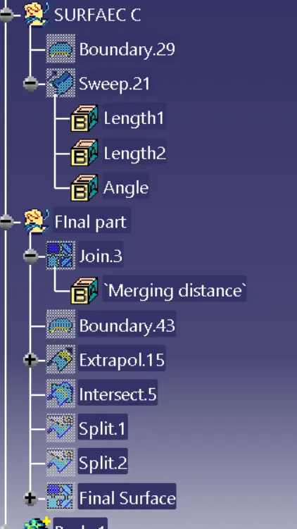
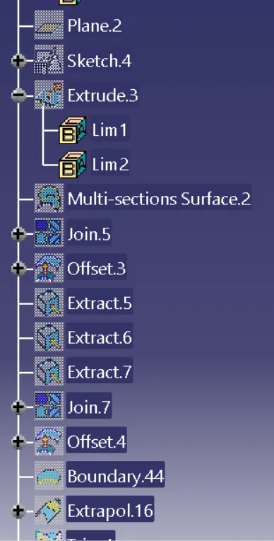
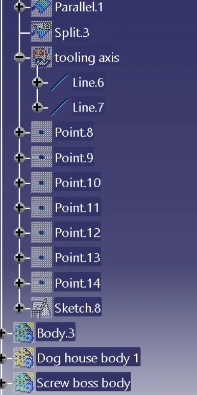
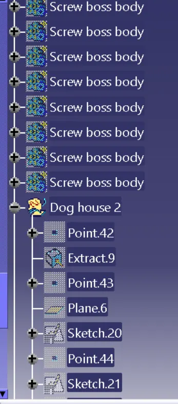
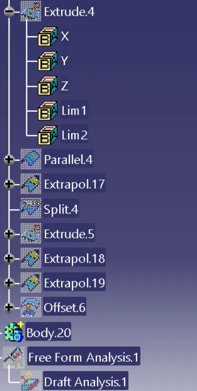
after that as per design guideline I have to attach a heat stake and dog house
For heatstakes we first created sketch and after that by using pad command we give 3d shape after that we use chamfer,edge filllet and boolean operation for final product.
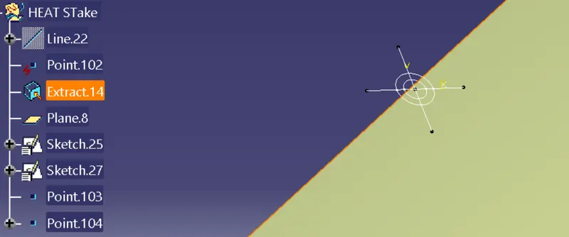
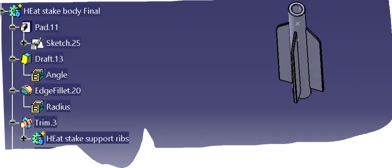
For dog house
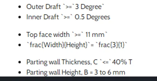
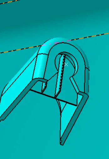
first I crete a sketch and then pad sketch and by using shell,pad and draft we created dog house as per dog house guideline
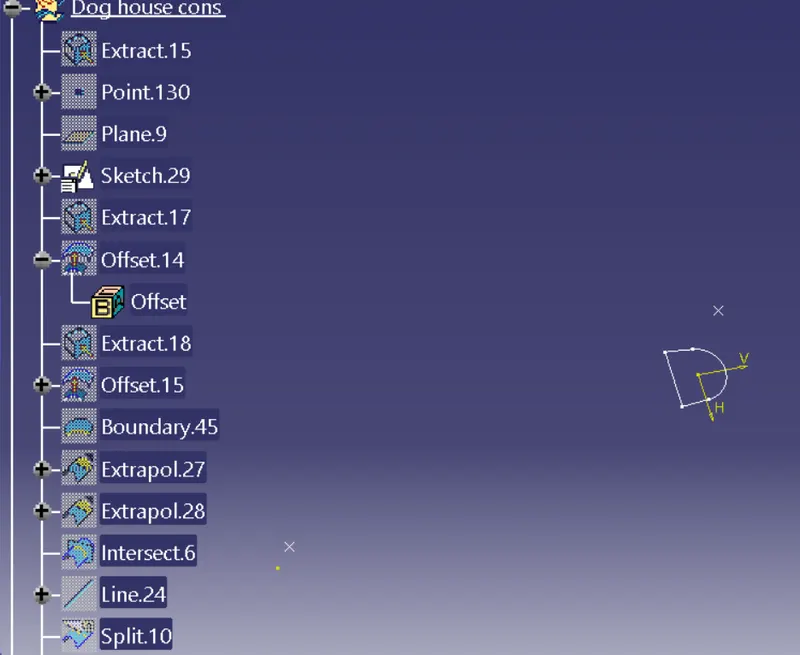
after pad i create corning area and at top of the dog house i created a circle 5mm dimension & with 38deg connecting line and pad that sketch and by using boolean operation i removed that area from dog house
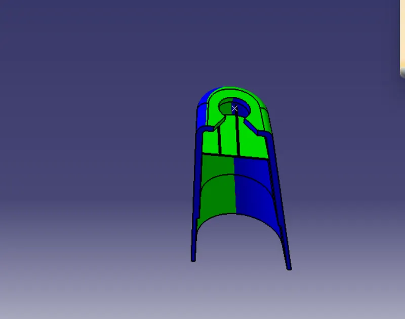
by using side core axis and main tooling axis we have to also analyze draft
and after that i copy and paste h.s at different position with use of trasition command by using point to point and dog house also and then by using boolean operation we get final body
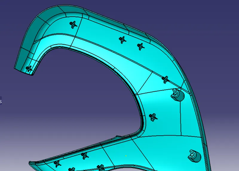
MAP POCKET- The map pocket body is in close contact with the door trim by the leaf spring when not in use, so that the space formed between the map pocket body and the door trim is variable by being supported by a leaf spring.
Surface A- Surface A is given by styling engineer
Tooling axis- we create a tooling axis by using point to direction method & The Draft Analysis allows the user to easily analyze a part for a proper draft angle.&
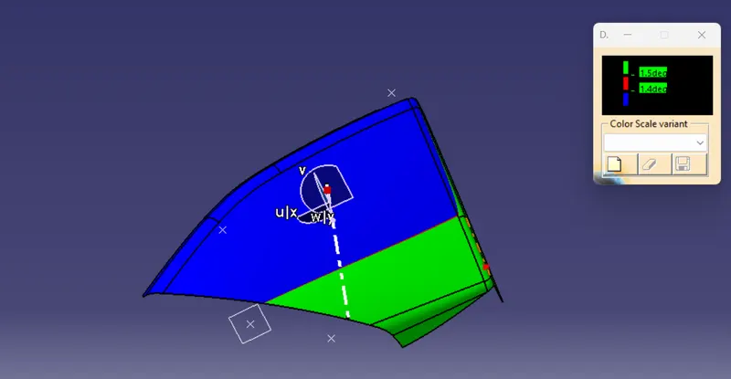
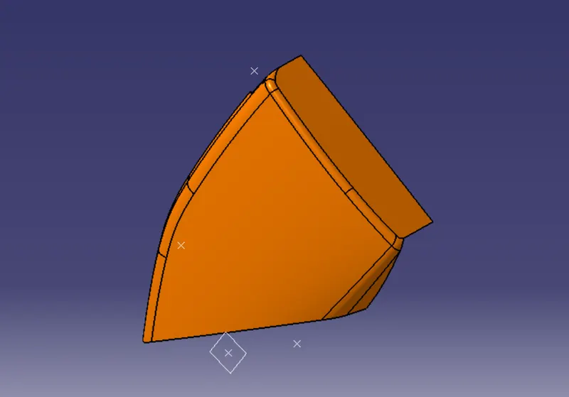
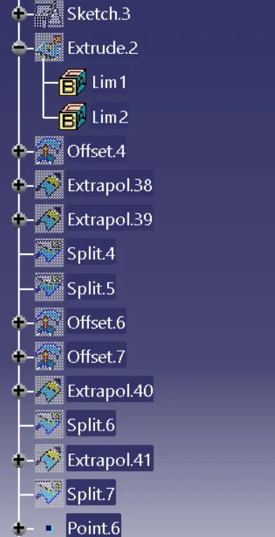
Surface B - By offset command at 2.5 mm we get B surface then after offset some surfaces are removed
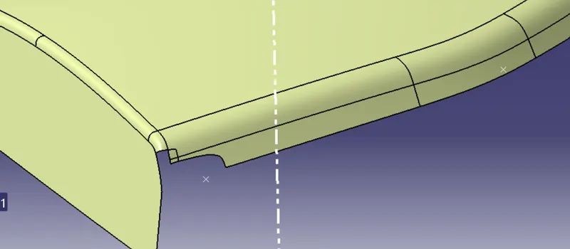
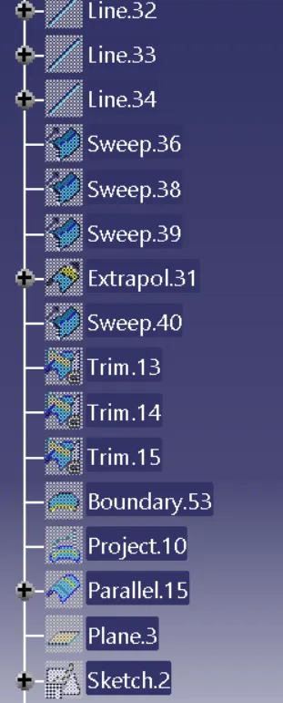
after using boundary command and mss command we create B surface and join them wwe get our new B surface
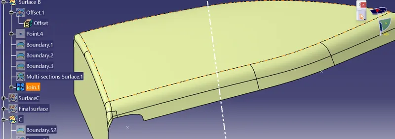
SURFACE C - Surface C is a joining element to join surface A & Surface B
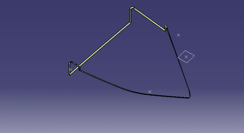 =
= 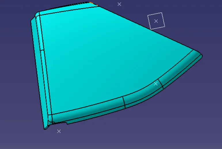
After that we trim the Surface B with Surface (A+C)
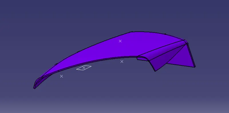
after that by using closed surface command we convert this surface in solid body
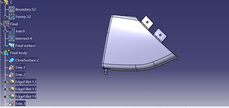
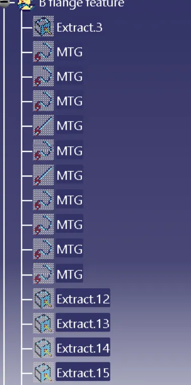
After that as per design requirement we create flanges by using some steps
ARM REST- Arm rest also a part of door assembly
Surface A- Surface A is a stlying surface that is given by engineers, it is also a reference surface
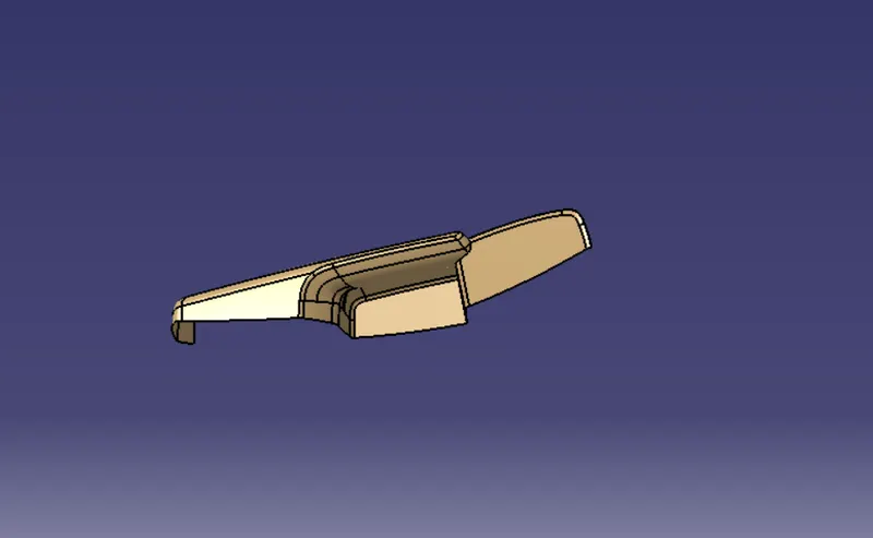
Improved surface A- In surface A we change some areas after that we create a new surface A and draft analysis of surface A
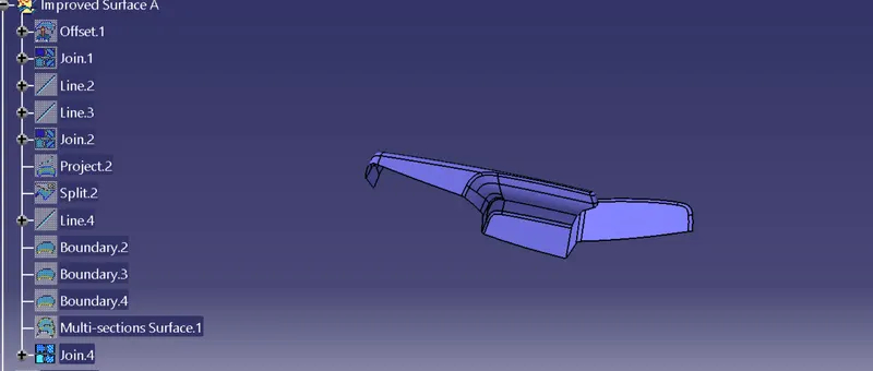
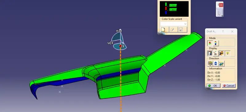
first we offset at 0 then by uusing line, boundary and mss commands we create New Surface A
TOOLING AXIS- In this extract a surface and by using the point command on the surface we create a point and point to direction by line command we created tooling axis .we create a tooling axis by using point to direction method & The Draft Analysis allows the user to easily analyze a part for a proper draft angle.
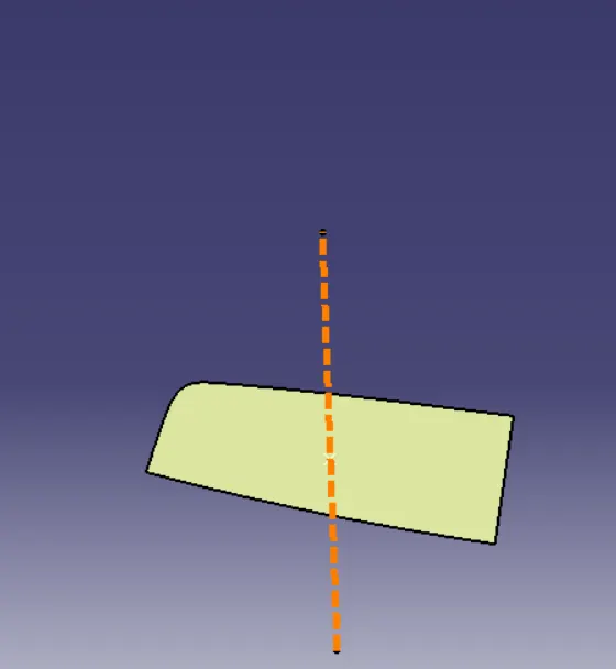
Surface B- First offset 2.5mm then some parts are removed then by using severl commands we created a SURFACE B
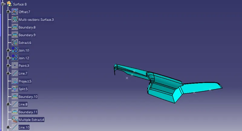
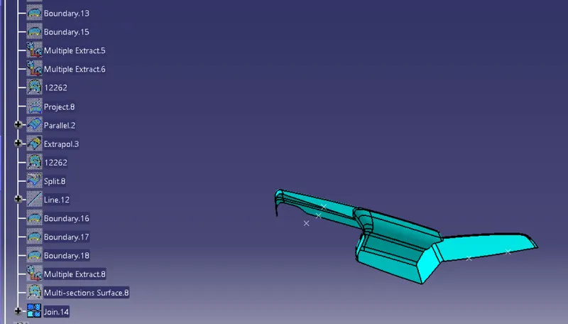
Surface C - SUrface C is a joining component that use to join A& B , first, we join A& C
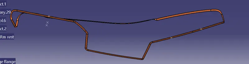
while creating surface C we follow several commands below
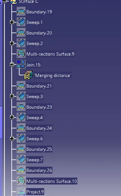
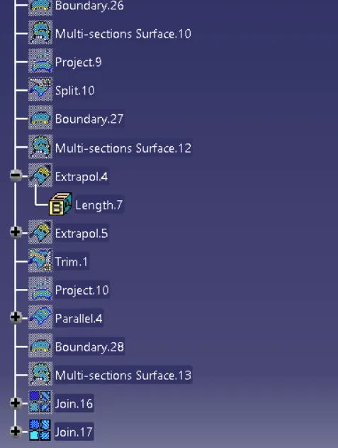
after that we join surface A and Surface C
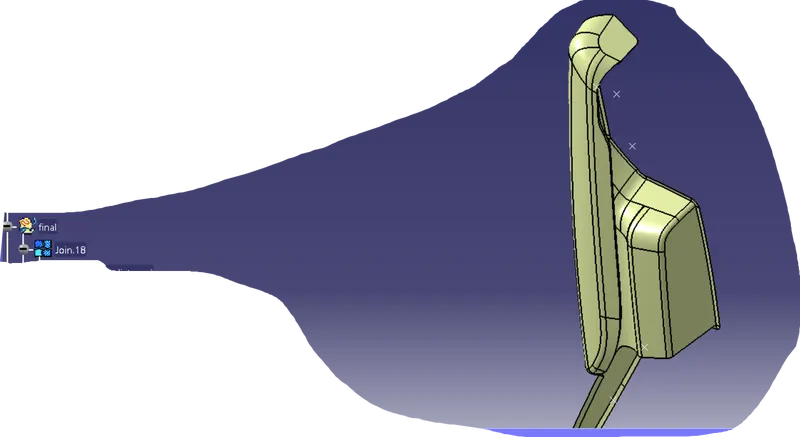
Then we use intersection command to check whether they cross each other or not after that by using the trim option we trim them and our final part is finished.
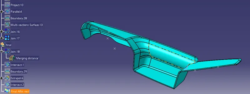
After that by using closed surface we get our solid part
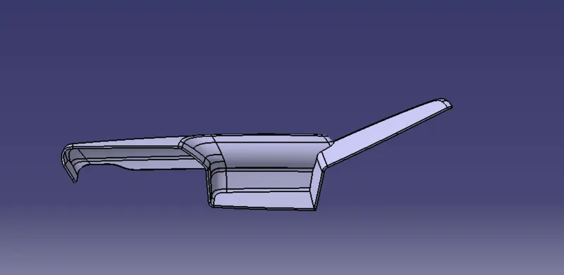
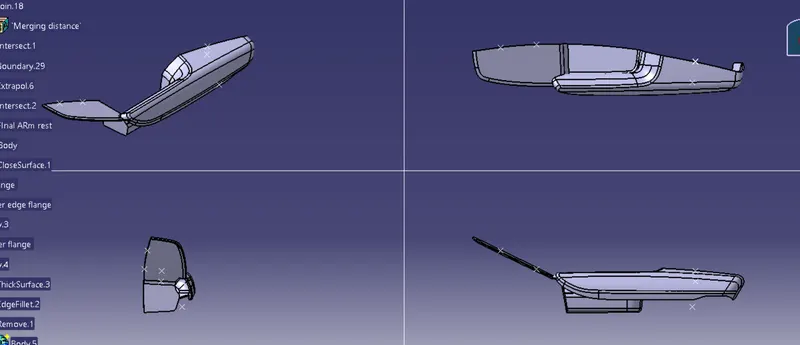
After that as per design requirement we create some flanges by using several commands
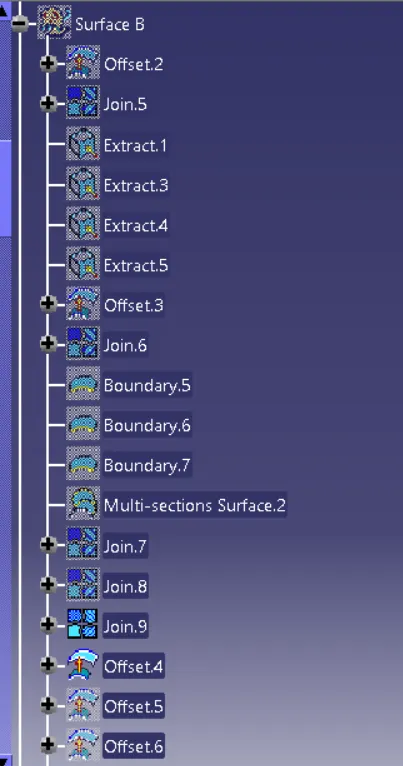
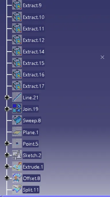
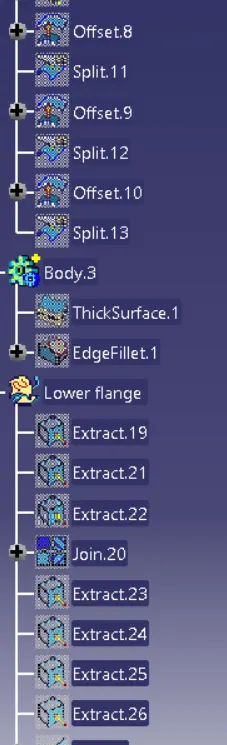
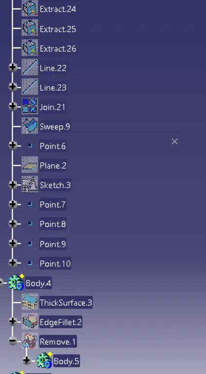

After that by using boolean operation we get desired part
Draft analysis-
Draft analysis- The draft analysis technique is used to analyze whether our part model created in CAD is manufacturable based on the draft condition applied. Here the part should get easily removed from the Mold
The Draft Analysis allows the user to easily analyze a part for a proper draft angle.
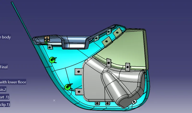
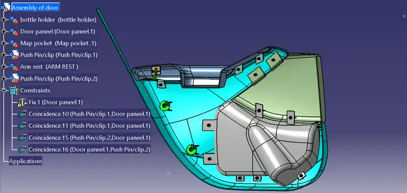
AT last we assemble all the parts and by using coinincidence command we get our final part
CONCLUSION - Creation of the car interior door trim is designed using the given class A surface as the input and Class B and C surface created with the help of Class A surface. By using the given master section attachment features I.e. Heat stakes, Flanges, Dog House and Push Clips are created using the design rules. The draft analysis has been performed to analysis the draft of the component to manufacture easily applying draft to the surface by 3 degree and 0.5 degree to the attachment features. With all data and report we can conclude that draft analysis is very important to design any plastic component to mold the plastic easily. The analysis will verify that all surfaces are favorable for being pulled from a cavity. It may also highlight or given insight to defect areas and b type feature are very important for joining one part to another.