Week 11 - Final project
AIM:
To design and development of vehicle interior door trim using Catia V5 with given class A surface along with Master section. Also create the Side Attachment features as per design rules.
OBJECTIVE:
- To create thickened part using master section for reference
- To create the mounting features as per design guidelines in the industry and with master sections
- To perform Draft analysis & Tooling analysis
PROCEDURE OF DOOR TRIM PANEL :
The door panel is divided into four parts for easly to design. There are,
- Door Arm Rest.
- Lower substrate.
- Outer Map Pocket.
- Inner Map Pocket.
A) Door Arm Rest :-
Step 1: Design Check (Pre Check) on received Class A :-
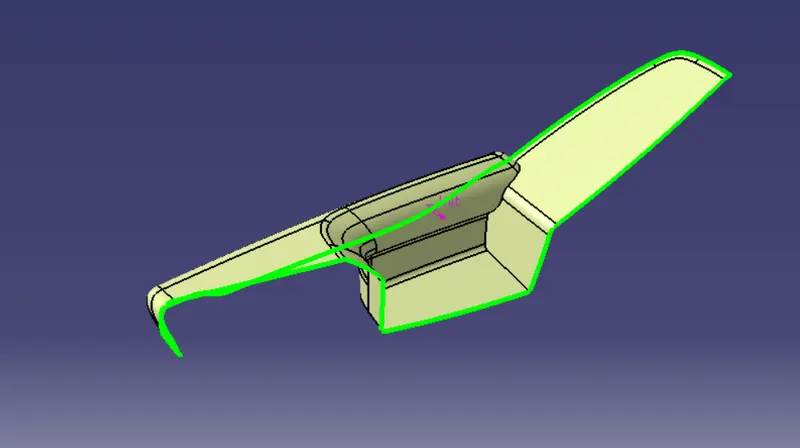
- After receiving the Class-A for the connectivity of the surfaces on it.
- Use boundary operation and disassemble.
- Check for discontinuous Surface.
- The check is over if any discontinuities do not arise.
Step 2: Determine the tooling Axis :-
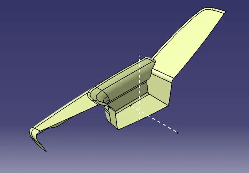
- Identify faces which can potentially create problems while manufacturing.
- Surfaces at angles along a desired Tooling Axis.
- Extract a plain surface and create a point on its center for Axis system creation.
Step 3: Draft Analysis on Class-A and Possible Creation of Side Tooling Axis :-
- Change View Mode Customization to Material mode.
- Go to INSERT--->ANALYSIS--->FEATURE DRAFT ANALYSIS and move the compass to the moving Axis.
- Change the range to 3°. Apply the settings as shown in below image.
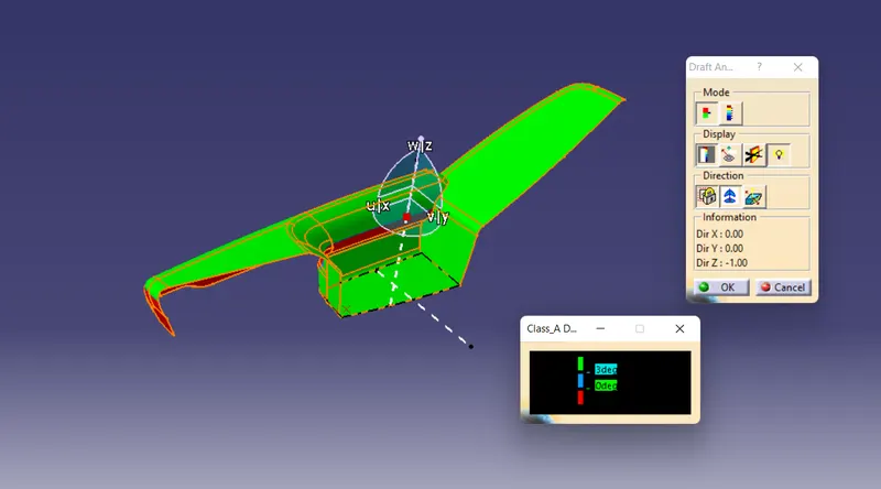
- The input Class A also has walls having negative angle to the tooling axis.
- This can be an issue while manufacturing the component as it would be very difficult to draw from the molds.
- So, this design needs to consider Various Side Tooling Options.
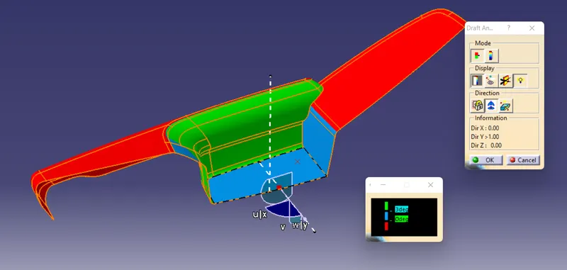
- Here also we can see that some faces are not clearing draft analysis and it is due to the improper class A surface and we have to imform our styling team to modify the class A surface.
Step 4: Class-B Surface Creation :-
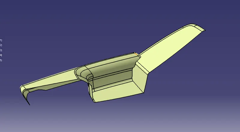
This can be done by offseting the class-A surface and by reparing the patches that are forrmed while offsetting the class-A surface.
- First offset the class-A surface
- We can observe it has created patches at two stages.
- So we have to repair them by using multi section surface command.
- Name the developed repaired surface ass Class-B Surface and make it publish.
Step 5: Class-C Surface Creation :-
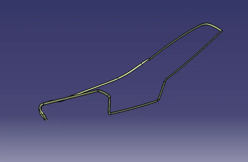
- Extract Class A boundary and convert to Smooth Curve.
- Sweep the curve to the Class A.
- Sweep value should be greater than the Thickness required for part.
- The obtained sweep is shown in Figure.
- Join the Class A Surface with the Class C surface to create a single surface entity.
Step 6: Enclosed Surface Creation :-
- Trim the obtained surface with Class B surface.
- Make Slight Adjustments by extrapolating small values and trimming to obtain a final Enclosed Surface.
- The final Enclosed Surface Obtained is shown in Figure.
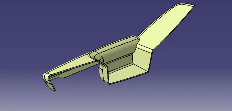
Closed Surface :-
Make the final trim to solid part using close surface.
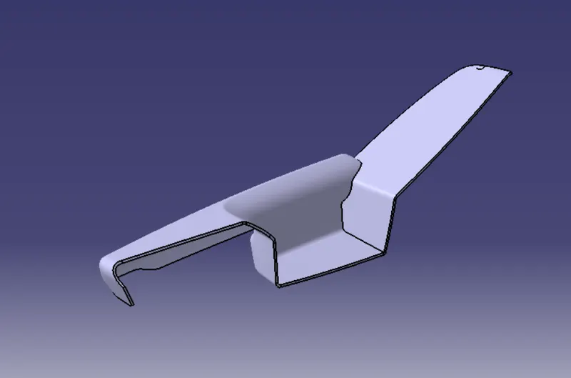
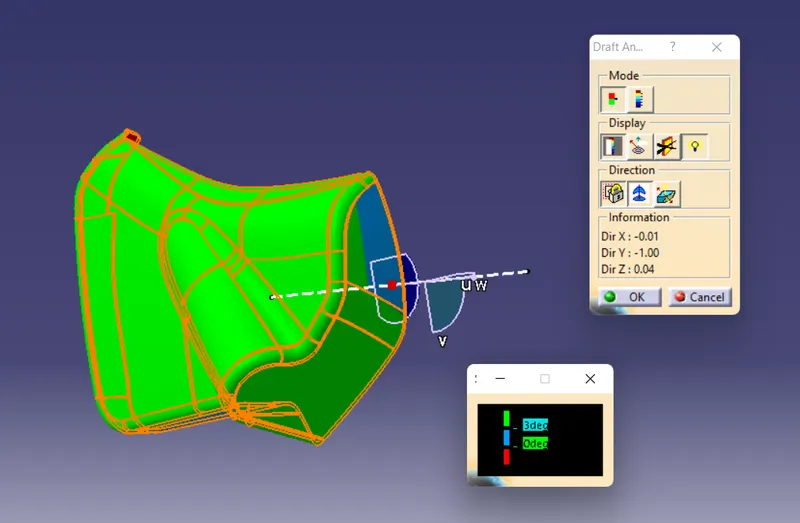
Step 7: Perform Draft Analysis on Final Enclosed Surface:
- Change View Mode Customization to Material mode.
- Go to INSERT---> ANALYSIS---> FEATURE DRAFT ANALYSIS and move the compass to the Main Tooling Axis.
- Change the range to 3°. Apply the settings as shown if Figure.
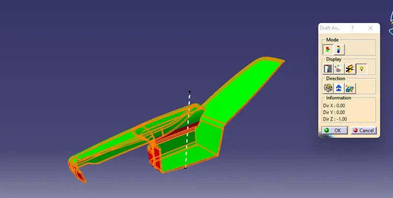
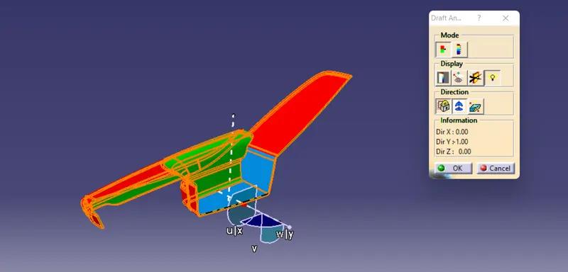
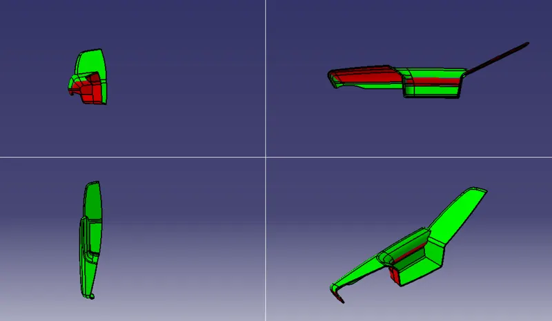
Views of Door Arm Panel :
B) Lower Substrate :-
Step 1: Design Check (Pre Check) on received Class A :-
- After receiving the Class-A for the connectivity of the surfaces on it.
- Use boundary operation and disassemble.
- Check for discontinuous Surface.
- The check is over if any discontinuities do not arise.
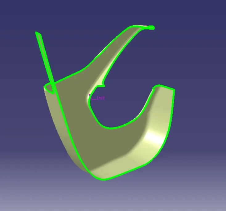
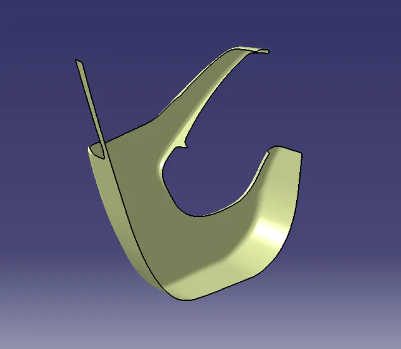
Step 2: Determine the tooling Axis :-
- Identify faces which can potentially create problems while manufacturing.
- Surfaces at angles along a desired Tooling Axis.
- Extract a plain surface and create a point on its center.
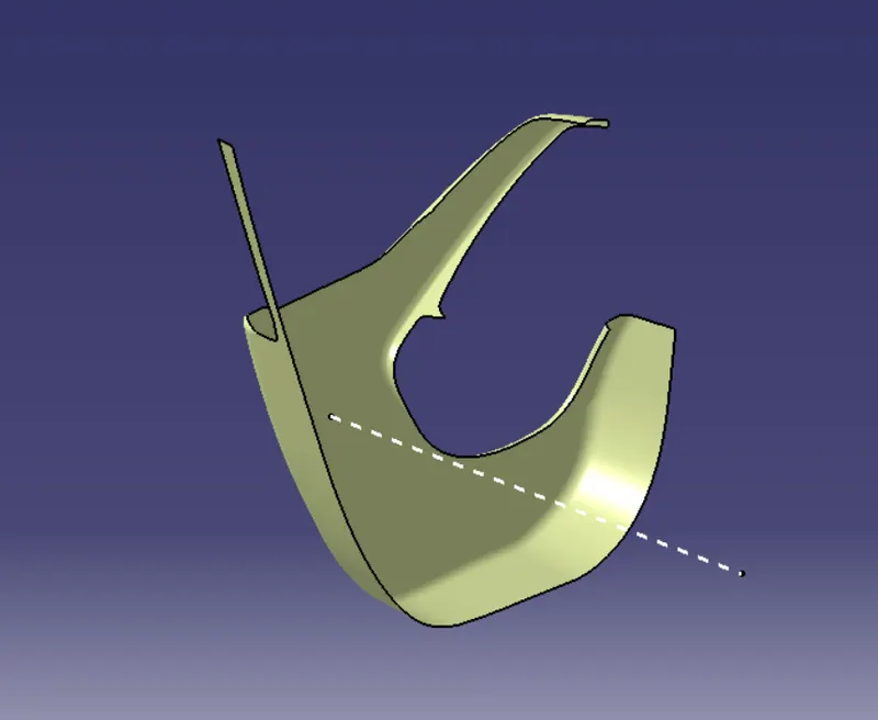
- Create the intersection by using the plane.
- Create the bisecting line for tooling axis by taking dummy tooling axis.
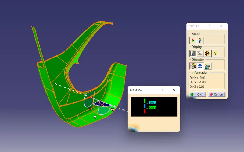
Step 3: Draft Analysis on Class-A :-
- Change View Mode Customization to Material mode.
- Go to INSERT--->ANALYSIS--->FEATURE DRAFT ANALYSIS and move the compass to the moving Axis.
- Change the range to 3°. Apply the settings as shown in below image.
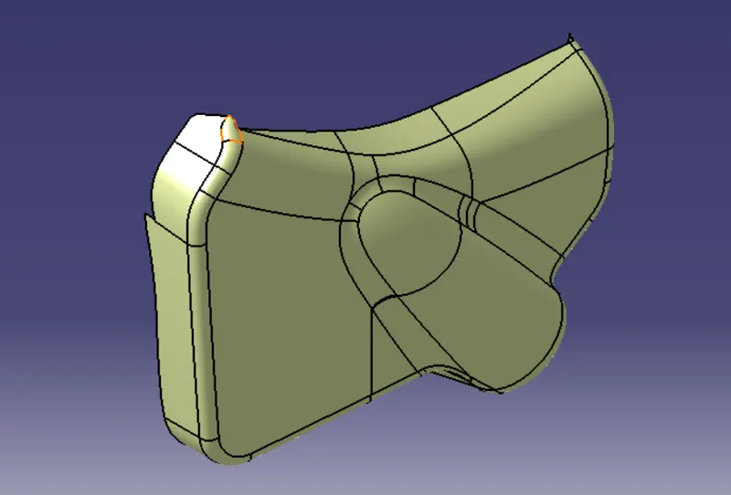
Step 4: Class-B Surface Creation :-
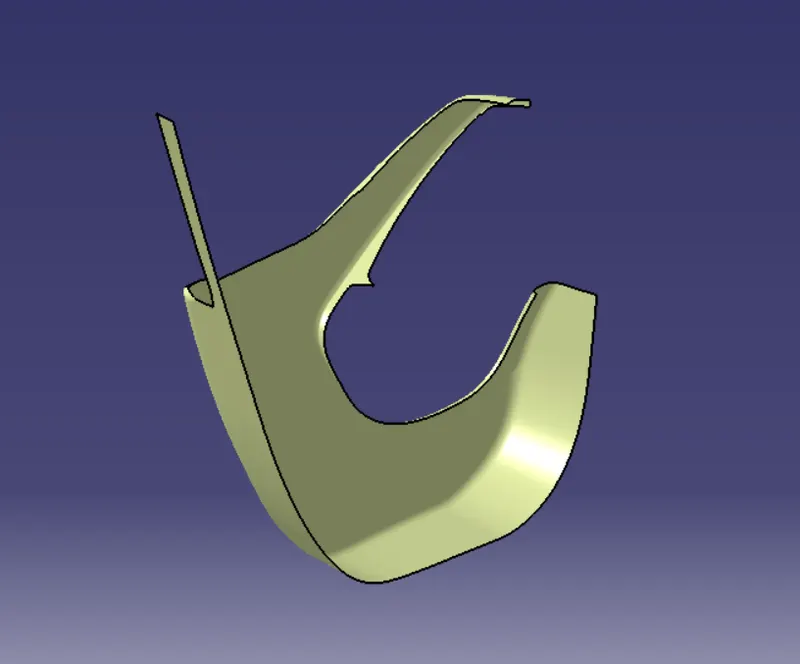
- The creation of class-B surface can be done by smiply offsetting the class-A surface to the required distance and required direction.
Step 5: Class-C Surface Creation :-
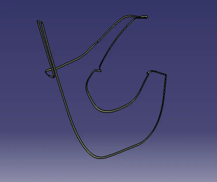
- Extract Class A boundary and convert to Smooth Curve.
- Sweep the curve to the Class A.
- Sweep value should be greater than the Thickness required for part.
- The obtained sweep is shown in Figure.
- Join the Class A Surface with the Class C surface to create a single surface entity.
Step 6: Enclosed Surface Creation :-
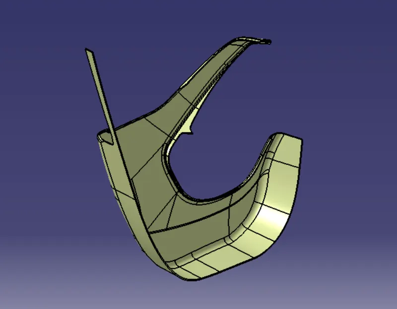
- Trim the obtained surface with Class B surface.
- Make Slight Adjustments by extrapolating small values and trimming to obtain a final Enclosed Surface.
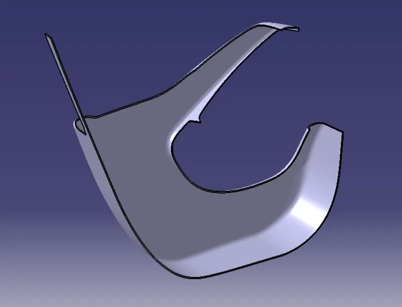
- The final Enclosed Surface Obtained is shown in Figure.
Closed Surface :-
Make the final trim to solid part using close surface.
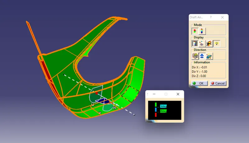
Step 7: Perform Draft Analysis on Final Enclosed Surface:
- Change View Mode Customization to Material mode.
- Go to INSERT---> ANALYSIS---> FEATURE DRAFT ANALYSIS and move the compass to the Main Tooling Axis.
- Change the range to 3°. Apply the settings as shown if Figure.
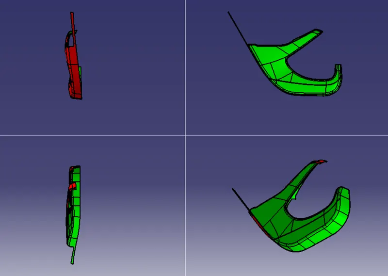
Views of Lower Substrate :
C) Outer Map Pocket :-
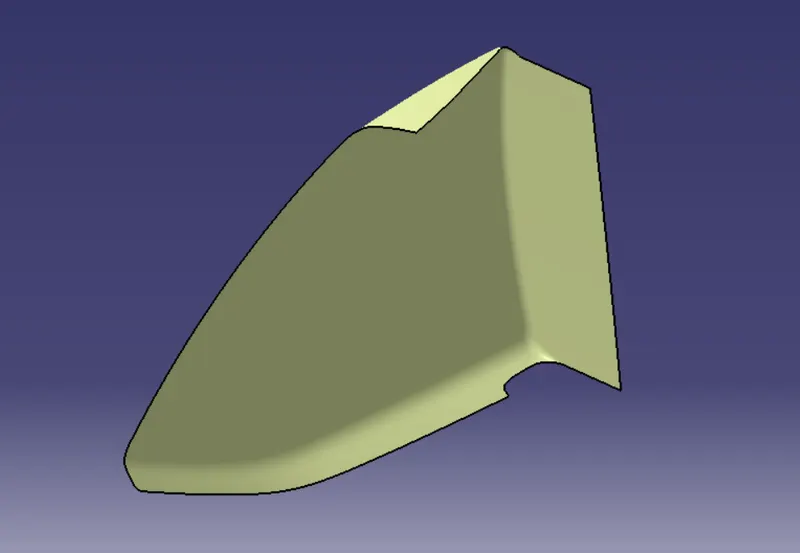
Step 1: Design Check (Pre Check) on received Class A :-
- After receiving the Class-A for the connectivity of the surfaces on it.
- Use boundary operation and disassemble.
- Check for discontinuous Surface.
- The check is over if any discontinuities do not arise.
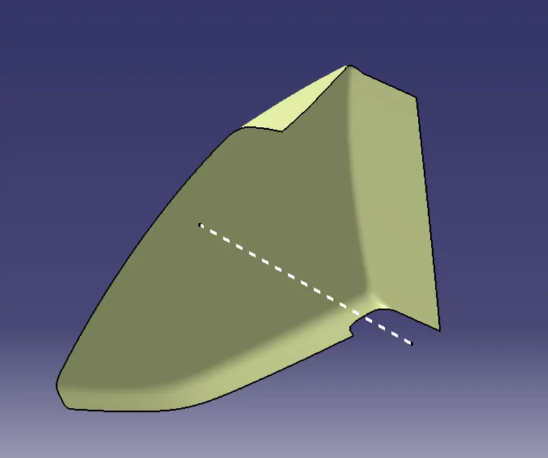
Step 2: Determine the tooling Axis :-
- Identify faces which can potentially create problems while manufacturing.
- Surfaces at angles along a desired Tooling Axis.
- Extract a plain surface and create a point on its center for Axis system creation.
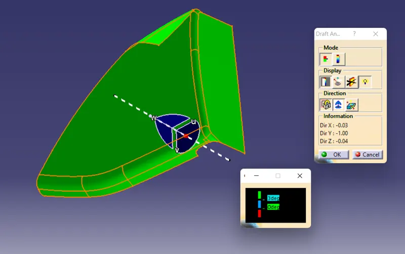
Step 3: Draft Analysis on Class-A :-
- Change View Mode Customization to Material mode.
- Go to INSERT--->ANALYSIS--->FEATURE DRAFT ANALYSIS and move the compass to the moving Axis.
- Change the range to 3°. Apply the settings as shown in below image.
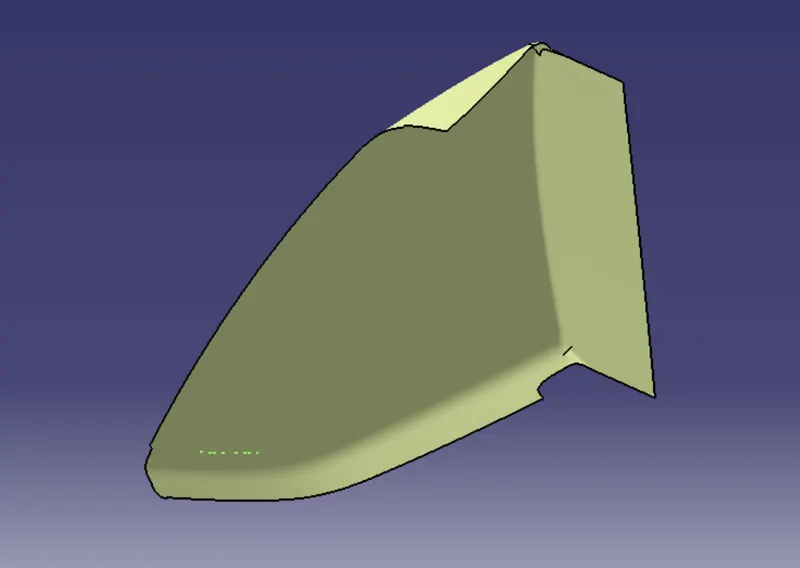
Step 4: Class-B Surface Creation :-
- The creation of class-B surface can be done by smiply offsetting the class-A surface to the required distance and required direction.
Step 5: Class-C Surface Creation :-
- Extract Class A boundary and convert to Smooth Curve.
- Sweep the curve to the Class A.
- Sweep value should be greater than the Thickness required for part.
- The obtained sweep is shown in Figure.
- Join the Class A Surface with the Class C surface to create a single surface entity.
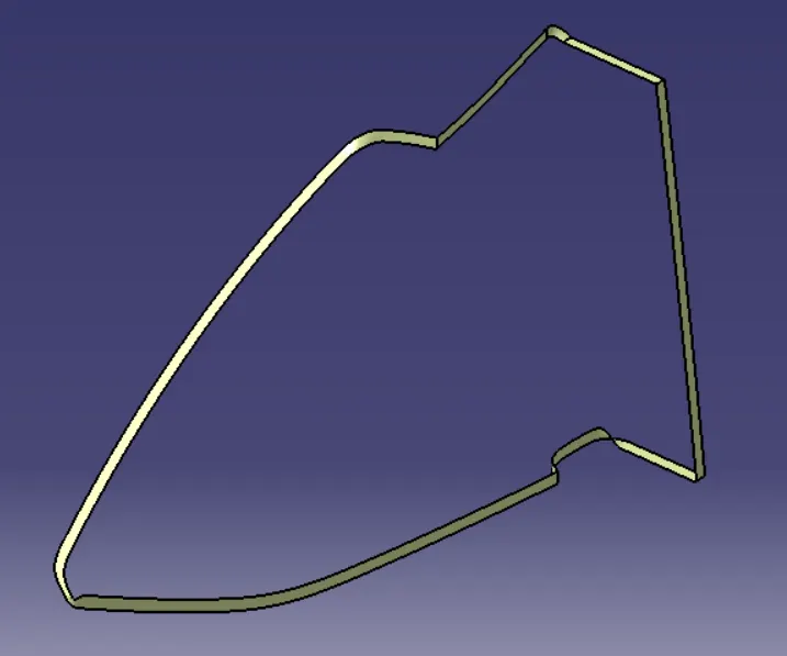
Step 6: Enclosed Surface Creation :-
- Trim the obtained surface with Class B surface.
- Make Slight Adjustments by extrapolating small values and trimming to obtain a final Enclosed Surface.
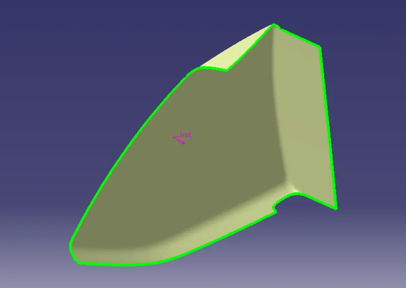
- The final Enclosed Surface Obtained is shown in Figure.
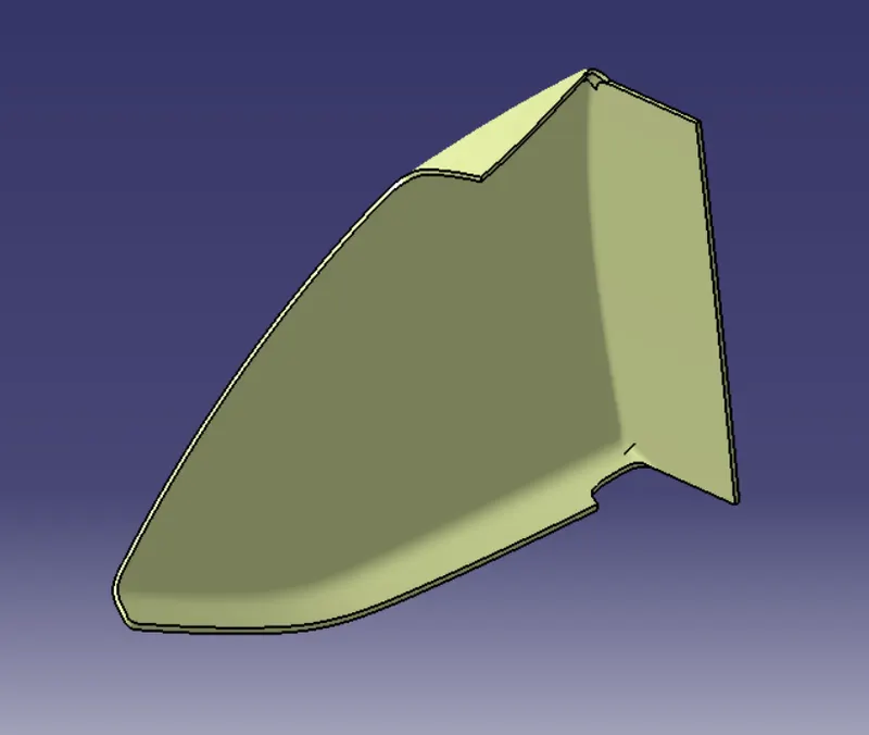
Closed Surface :-
Make the final trim to solid part using close surface.
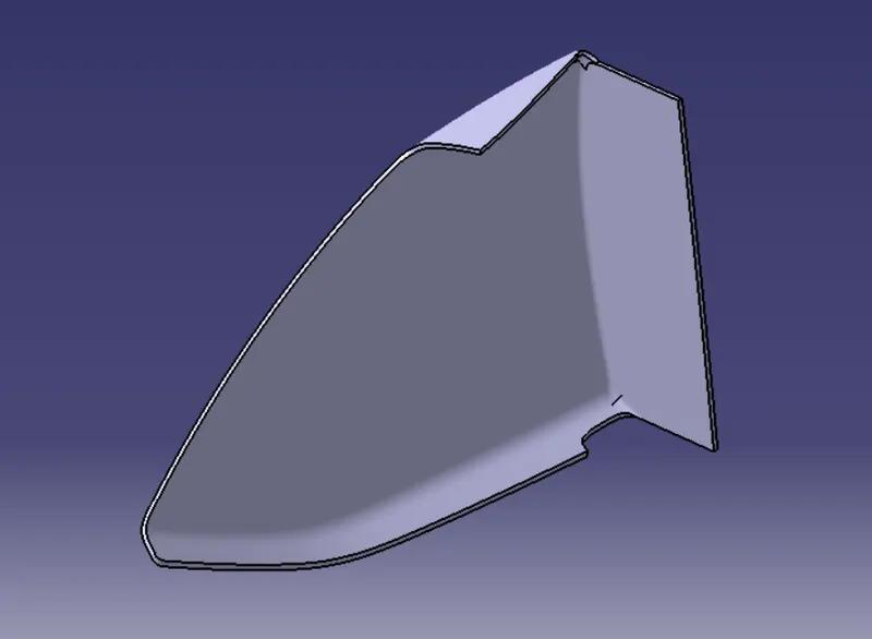
Step 7: Perform Draft Analysis on Final Enclosed Surface:
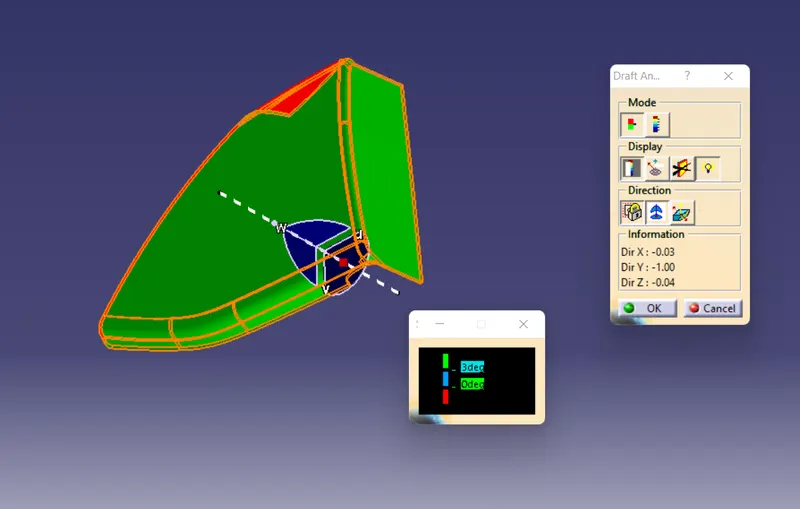
- Change View Mode Customization to Material mode.
- Go to INSERT---> ANALYSIS---> FEATURE DRAFT ANALYSIS and move the compass to the Main Tooling Axis.
- Change the range to 3°. Apply the settings as shown if Figure.
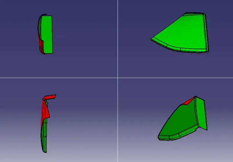
Views of Outer Map Pocket :
D) Inner Map Panel :
Step 1: Design Check (Pre Check) on received Class A :-
- After receiving the Class-A for the connectivity of the surfaces on it.
- Use boundary operation and disassemble.
- Check for discontinuous Surface.
- The check is over if any discontinuities do not arise.
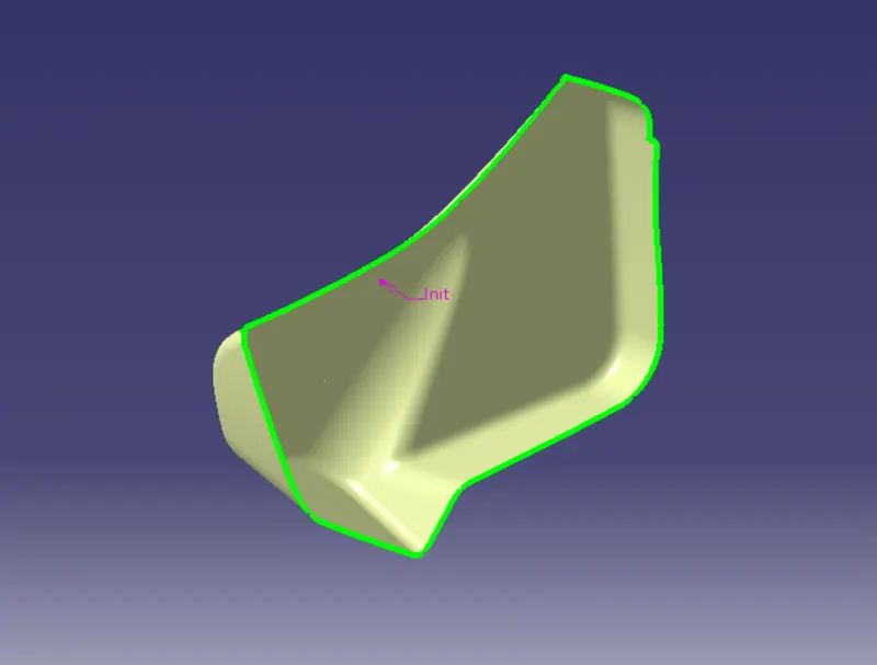
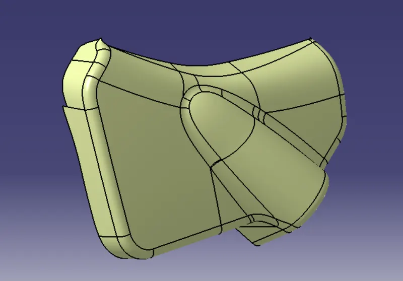
Step 2: Determine the tooling Axis :-
- Identify faces which can potentially create problems while manufacturing.
- Surfaces at angles along a desired Tooling Axis.
- Extract a plain surface and create a point on its center.
- Create the intersection by using the plane.
- Create the bisecting line for tooling axis by taking dummy tooling axis.
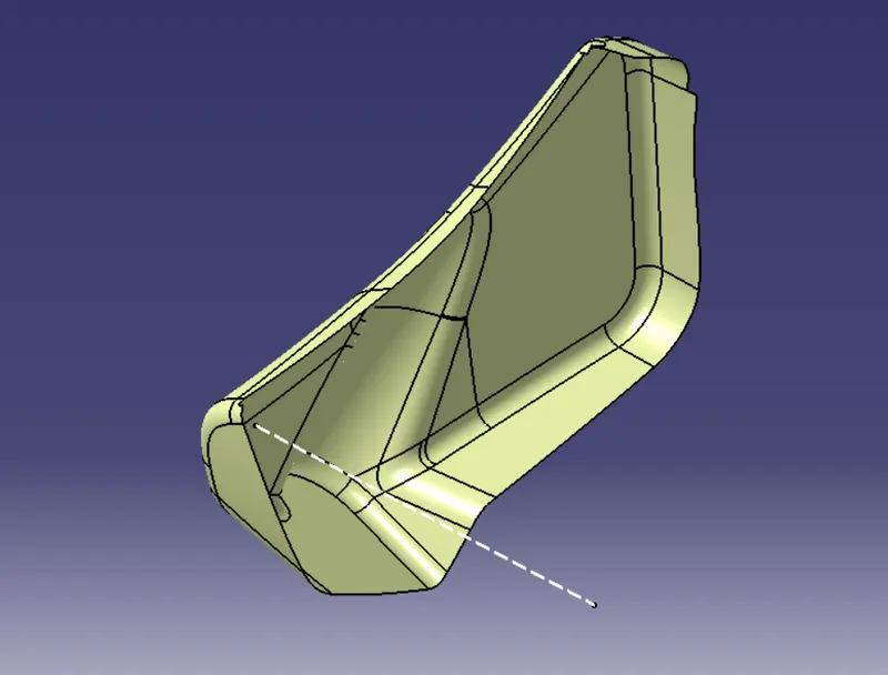
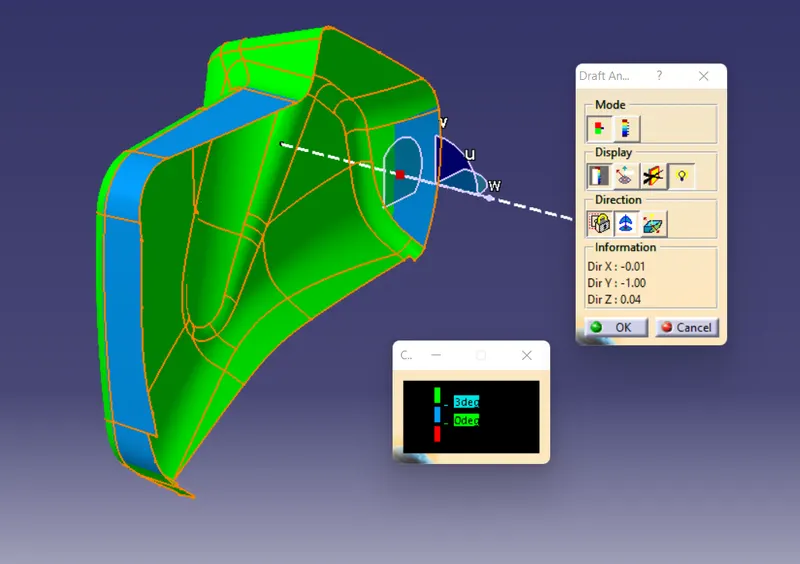
Step 3: Draft Analysis on Class-A :-
- Change View Mode Customization to Material mode.
- Go to INSERT--->ANALYSIS--->FEATURE DRAFT ANALYSIS and move the compass to the moving Axis.
- Change the range to 3°. Apply the settings as shown in below image.
Step 4: Class-B Surface Creation :-
- The creation of class-B surface can be done by smiply offsetting the class-A surface to the required distance and required direction.
Step 5: Class-C Surface Creation :-
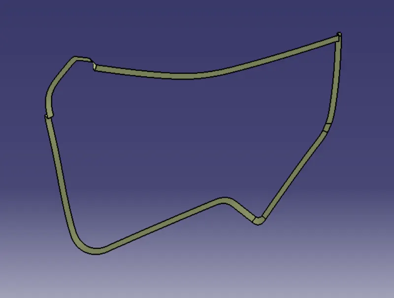
- Extract Class A boundary and convert to Smooth Curve.
- Sweep the curve to the Class A.
- Sweep value should be greater than the Thickness required for part.
- The obtained sweep is shown in Figure.
- Join the Class A Surface with the Class C surface to create a single surface entity.
Step 6: Enclosed Surface Creation :-
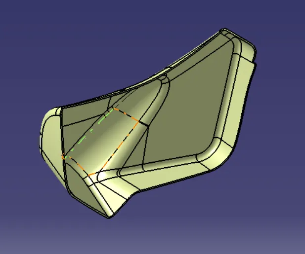
- Trim the obtained surface with Class B surface.
- Make Slight Adjustments by extrapolating small values and trimming to obtain a final Enclosed Surface.
- The final Enclosed Surface Obtained is shown in Figure.
Closed Surface :-
Make the final trim to solid part using close surface.
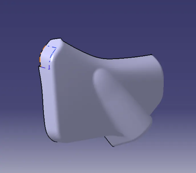
Step 7: Perform Draft Analysis on Final Enclosed Surface:
- Change View Mode Customization to Material mode.
- Go to INSERT---> ANALYSIS---> FEATURE DRAFT ANALYSIS and move the compass to the Main Tooling Axis.
- Change the range to 3°. Apply the settings as shown if Figure.
- Creation of Attachment Feature to the Door Trim:
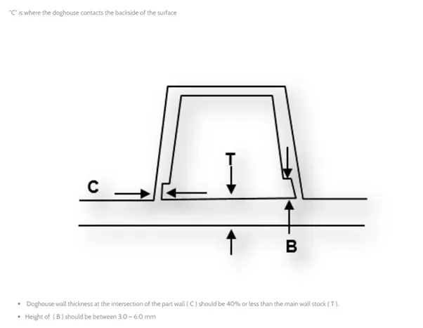
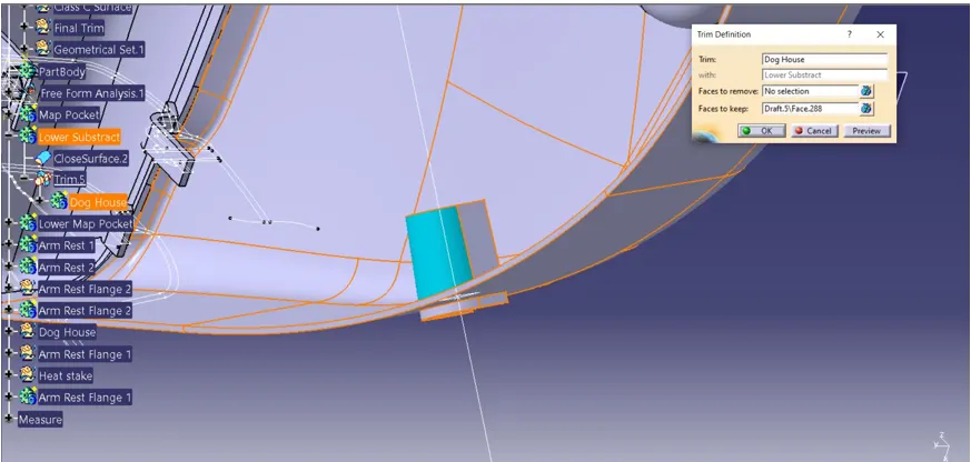
Dog house is an engineering feature used in plastic trim design. Dog houses are used as supporting feature. Sometimes other engineering features like snaps; locators etc. are mounded on them to increase their strength. Dog houses are subjected to draft analysis to prevent breakage of the component during ejection from mould cavity. Dog house and other engineering components are built on B-surface
Step: 1
Creating the sketch by extracting the class A surface, by each surfaces separately, point and axis system created simultaneously on the surface. Using positioned sketch making as shown below.
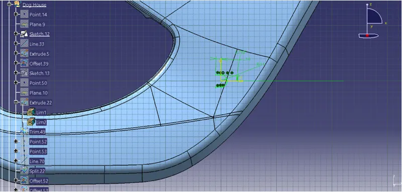
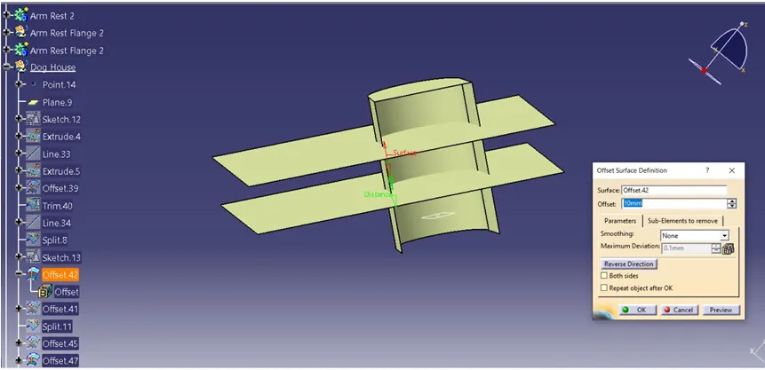
Step: 2
The extruded surface is extrapolated, the extract surface from Class A has been offset to make side wall surface of dog house by trimming it.
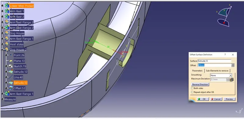
Step: 3
The extruded surface is converted into solid by thickening the surface for 2mm and it is extrapolated and to make close body it is split into equal distance has shown below.
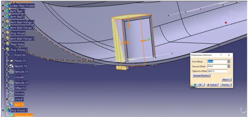
It is drafted for 0.5 deg to perpendicular to the sidling axis as shown below. The edges where chamfered for 5mm to 45 Degree.
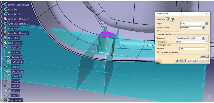
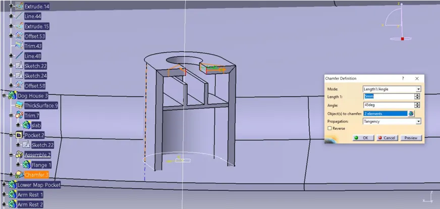
Step: 4
The undercut has been made by extrapolated surface and it is offset to the minimal value and it is trimmed to get perfect under cut.
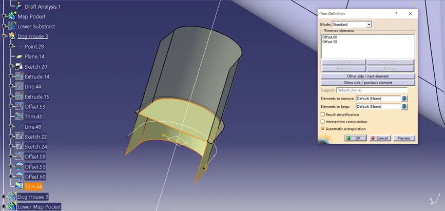
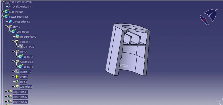
To get the proper clearance for removal of the component is drafted for 0.5 at the undercut area and it is chamfered for 1 mm to 38 deg as shown below.
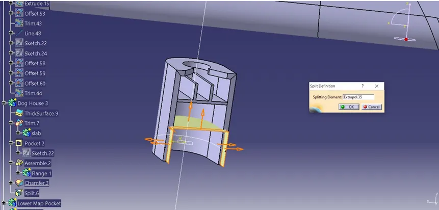
Step: 4
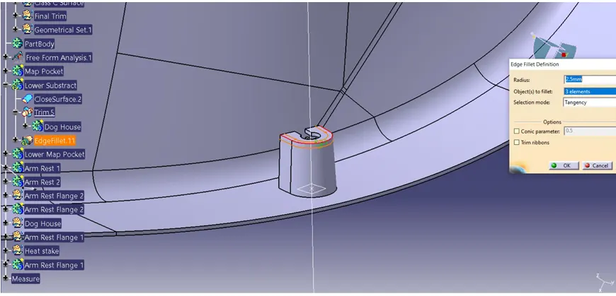
It is union trimmed to lower substrate and it is filleted for radius 2.5mm of smooth edges as shown below.
- Creating the Heat Stake:
Heat staking is a pulsed – heat process to join two or more parts out of which one at least is made of plastic . The plastic is to deform the plastic material using the heat and foam at a set process time. The bond is made by partially de forming the plastic part in order to fix the other. Heat stakes makes it easily to bond metal to plastic is commonly used in high volume and low cost application such as Automotive, IT and consumer appliances.
Step: 1
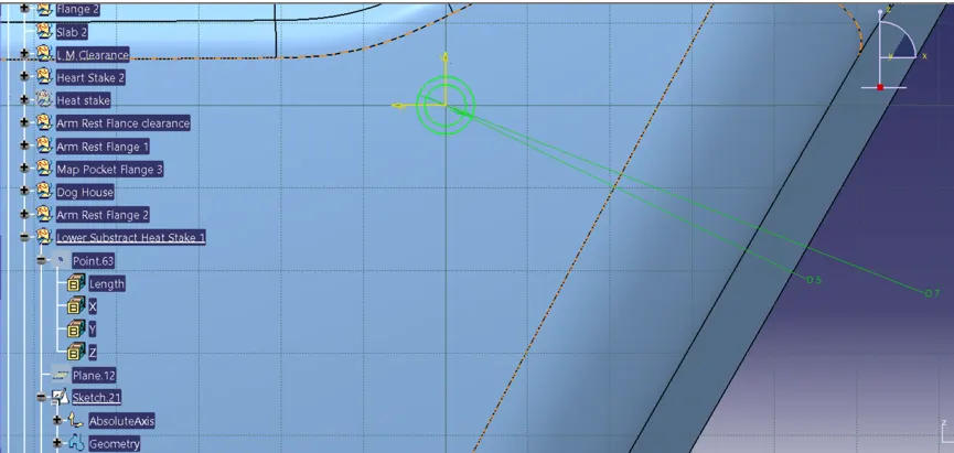
Creating the sketch by extracting the class A surface, by each surfaces separately, point and axis system created simultaneously on the surface. Using positioned sketch.
Step: 2
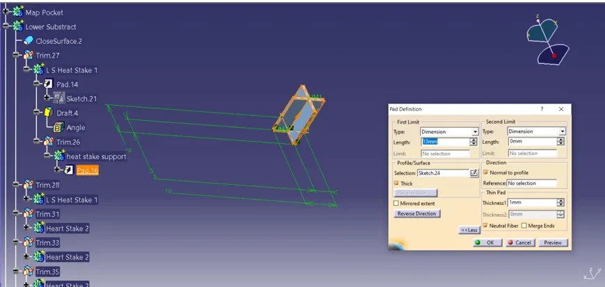
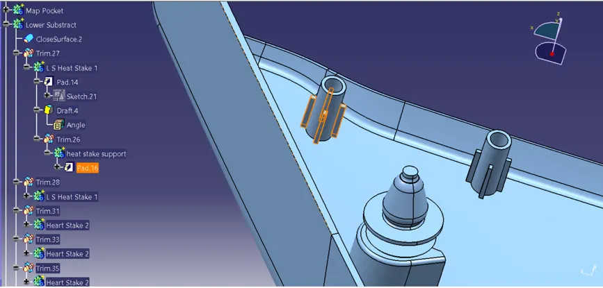
The sketch feature is then extracted to the required dimension. And it is drafted for the 0.5 deg to the sliding tooling axis, it is filleted for radius 0.25 of smooth edges as shown below.
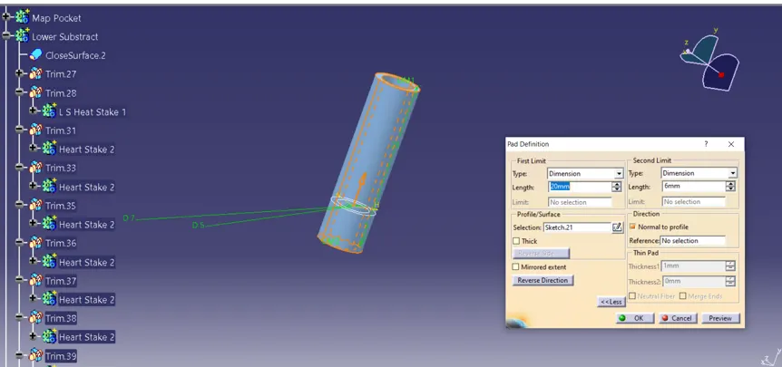
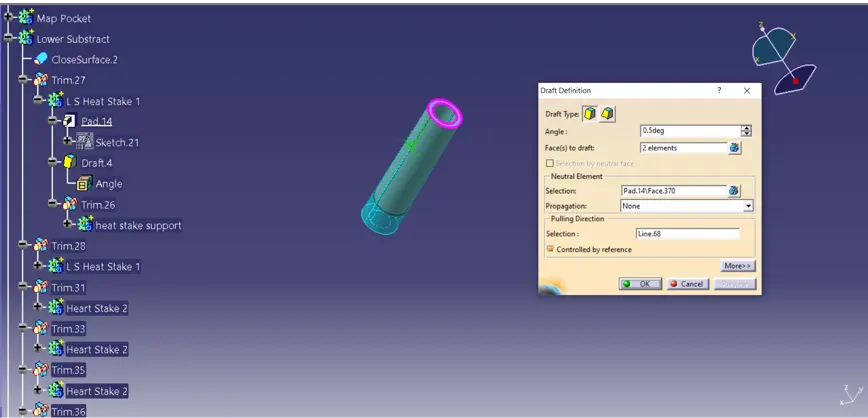
The support rib as created, where the flange will come and sits to get arrested to the heat stake.