Week 11 - Final project
AIM:
To design the car door inner panel with reference to given Class-A surface by using given mastersection, creating attachment features and performing draft analysis to check the manufacturing feasibility of the component by using software CATIA V5.
Objective:
The project deals with the explanation of method followed to develop door trim inner panel. In this with the given Class-A surface, Class-B surface and Class-C surface were created along with the tooling axis. Other attachment features were also created for assembly of the different components of door trim.
Methodology:
The methodology of the project is explained here:
1. Class-A suface was extracted from the given surface.
2. Tooling Axis were created of the individual component.
3. Class-B and Class-C surface were created with the OEM guidelines.
4. Formed Solid body from the closed surface.
5. Engineering features were created for attachment.
6. Draft analyses of each component was performed to check the manufacturing feasibility.
CREATING TOOLING :
First we need to clear the draft analysis for CLASS A surafce so first we need to create the TOOLING AXIS for all CLASS A surface then we clear the draft for all components
To creating the tooling there is two types of creating the tooling axis one is to look the class a surface which dirction of composs to cover or show the maximum compontes then we simply create the POINT TO DIRECTION method and another one is bisecting line method i using those methods to create the tooling axis
TOOLING AXIS FOR ALL COMPONENTS :
DOOR ARM REST:
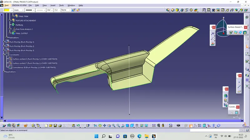
LOWER SUBSTRATE :
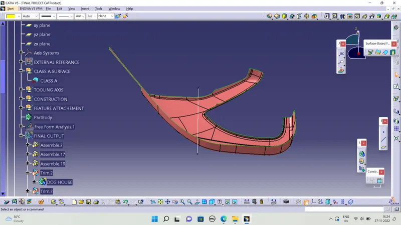
MAP POCKET :
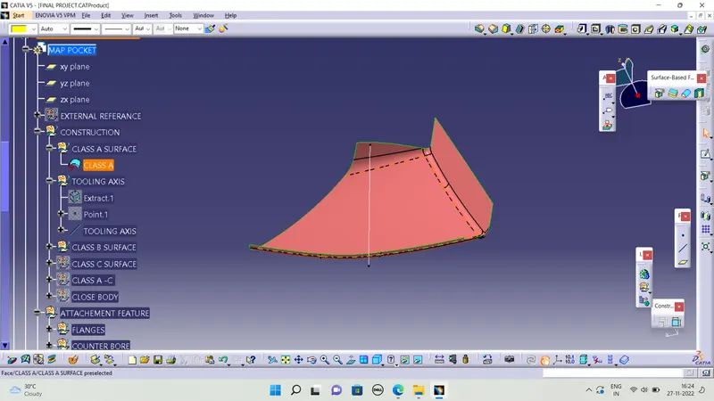
BOTTLE HOLDER :
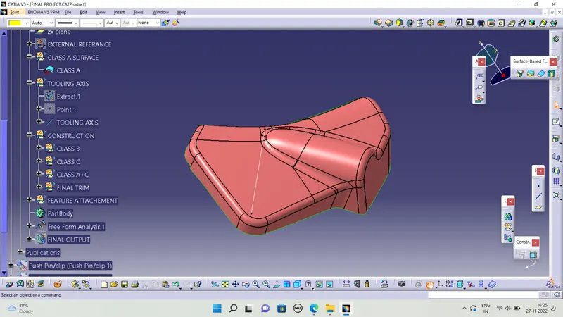
DRAFT ANALYSIS FOR CLASS A SURFACE :
In some door arm rest have small patches in class a surface and i work on it to clear the patches i perform the draft analysis in class a surface
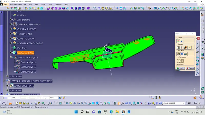
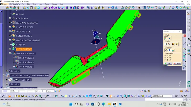
and map pocket and lower subsrate are class a surface some areas are not clear in draft analysis and ask they told go on work on it and i create the class b surface in that components in not clear in the draft for close surface i attached below the images
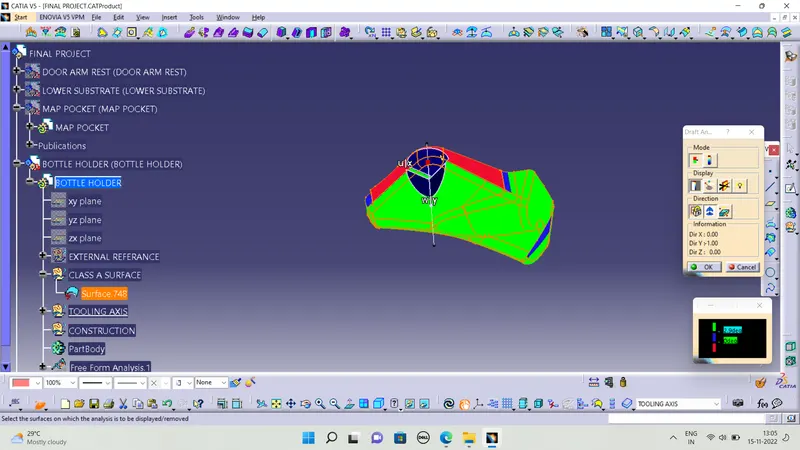
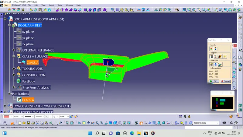
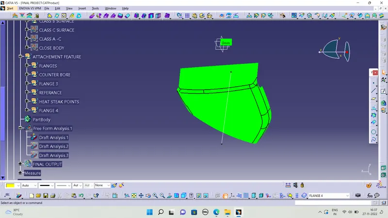
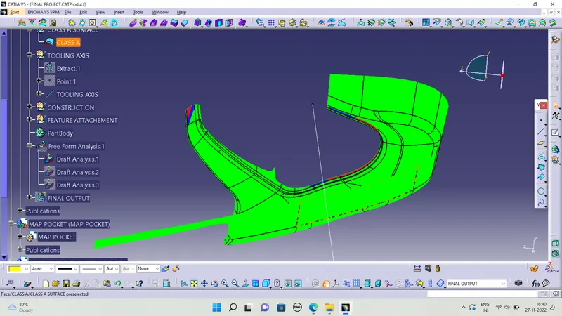
In some areas of CLASS A surface are not clear in draft analysis MAP POCKET is only surface is clear in all areas remaining three components are not fully cleared
CREATING CLASS B SURFACE :
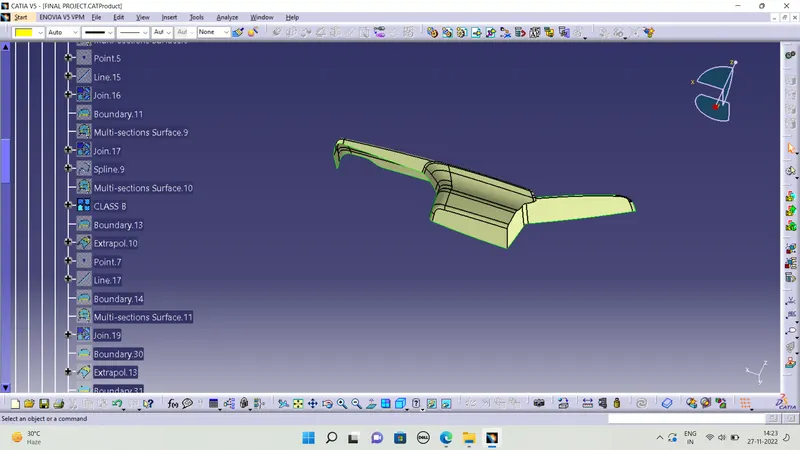
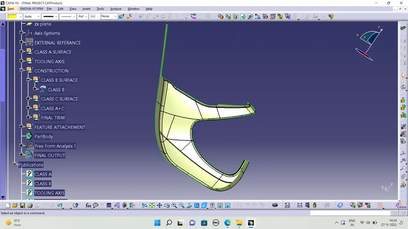
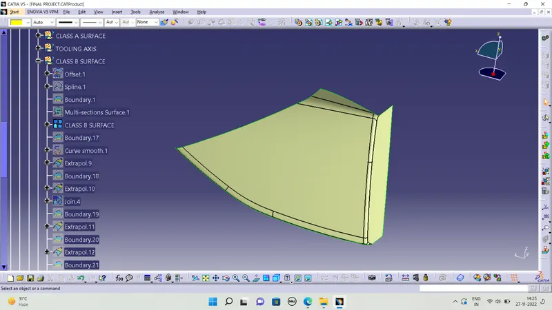
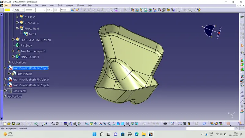
In class b surface creating i simply give a offset 2.5mm and some areas was not coming in clear output that patches using extrapolation and trim method i used to clear those patches
CLASS B SURFACE :
CLASS C SURFACE :
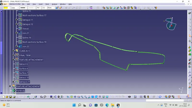
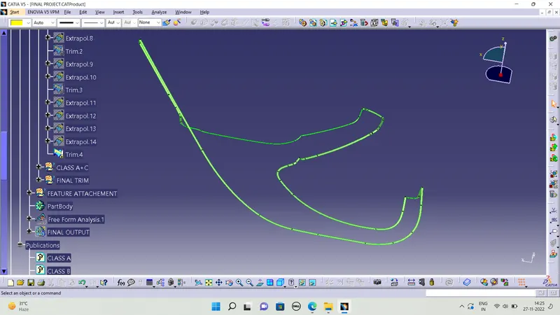
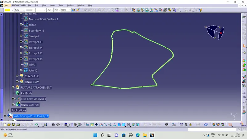
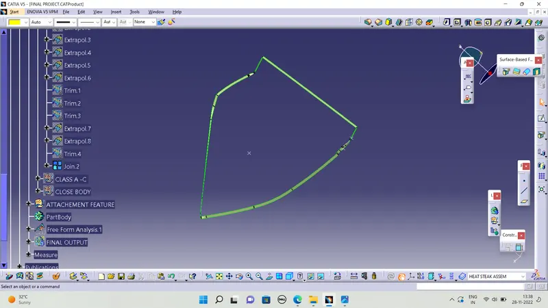
Creating class c surface sweep the curves in class a surface i use draft dircetion and referance surafce both method i used to create the class c suraface
CLOSE SURFACE :
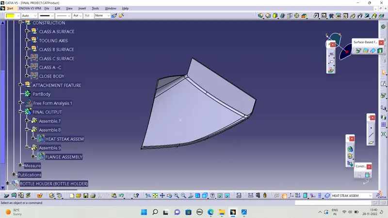
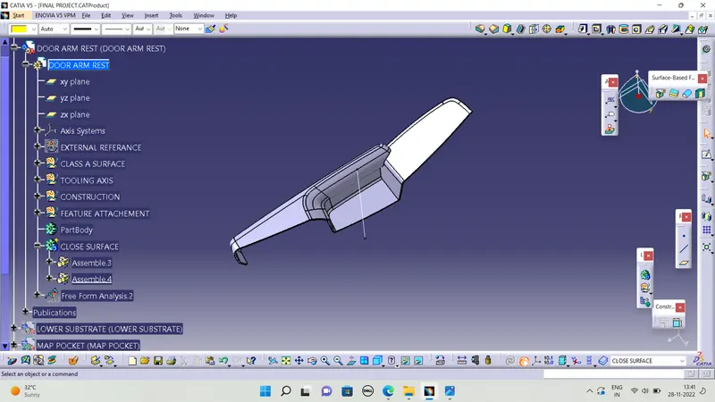
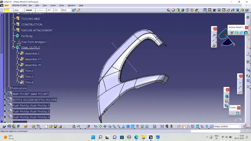
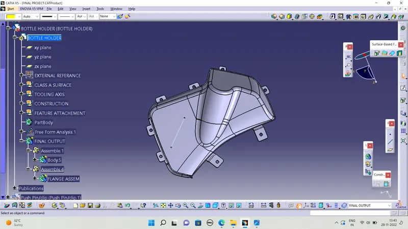
DRAFT ANALYSIS FOR CLOSE SURFACE :
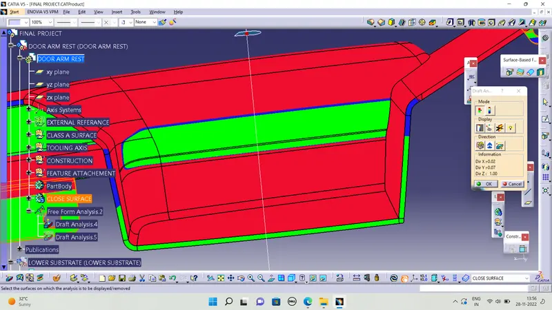
Once we created the close surface then we perforemd with draft analysis in all components with 3 degree draft and we performed the draft in some areas are not clear with a draft analysis why because the class surface also not fully cleared with a draft analysis then i proceed with the components to created the feature attachements
MAP POCKET :
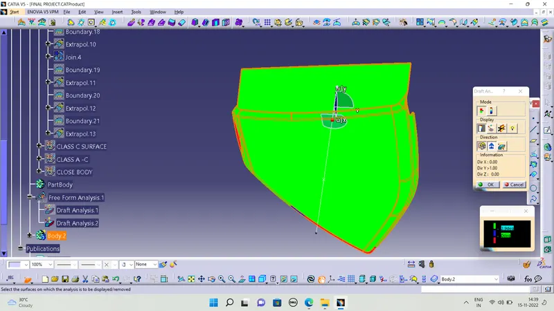
IN SOME AREAS WAS NOT CLEAR WITH DRAFT WHEN WE CHANGE THE COMPOSS DIRCTION IT WAS CLEARED WITH 3 DEGREE
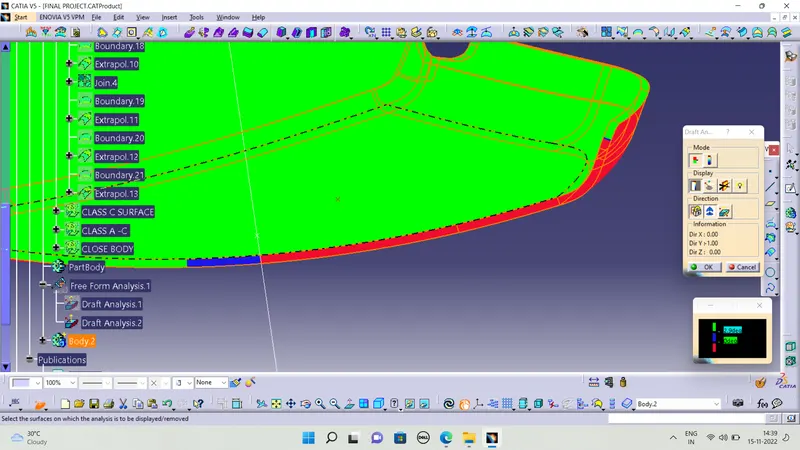
BOTTLE HOLDER :
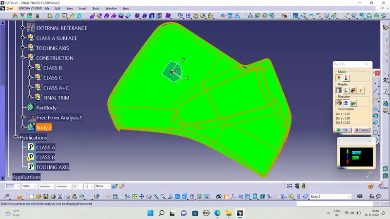
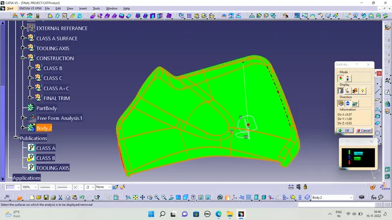
LOWER SUBSTRATE :
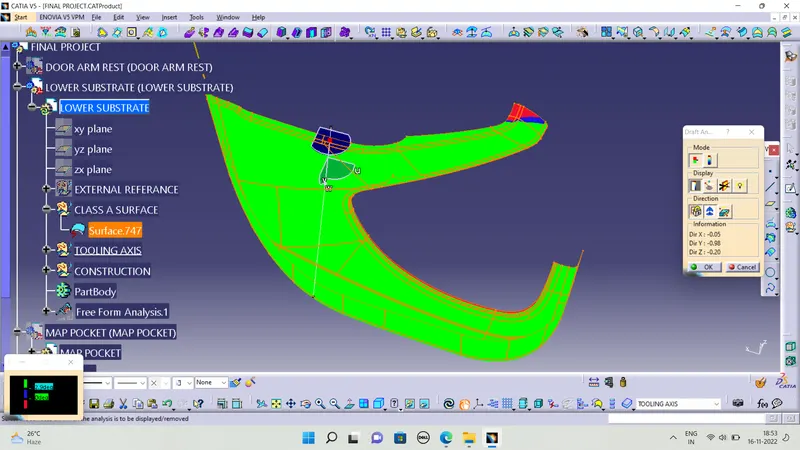
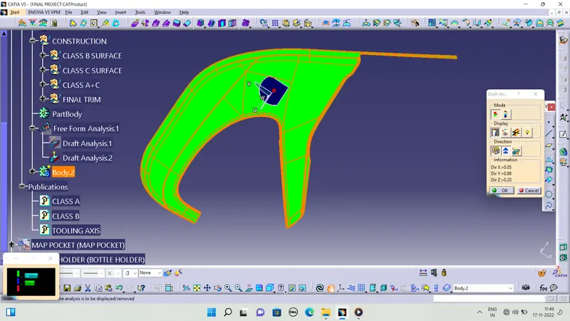
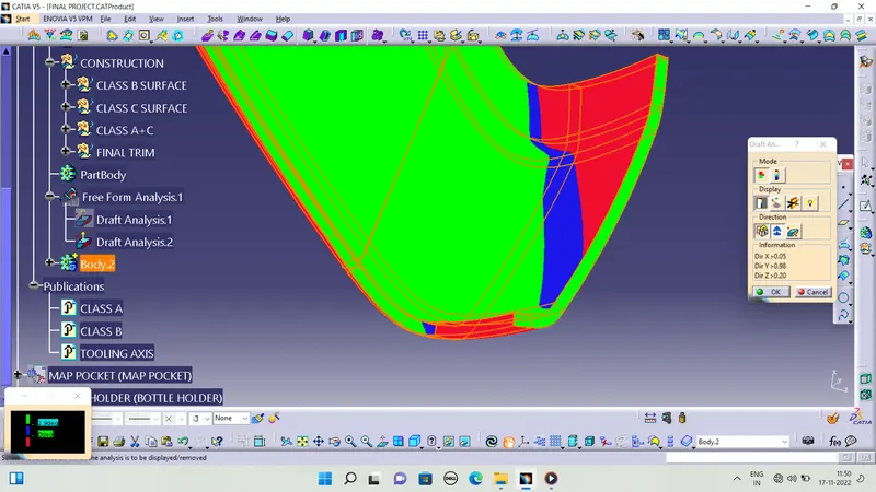
HERE SMALL PATCHES WAS NOT CLEARED WITH A DRAFT
DOOR ARM REST :
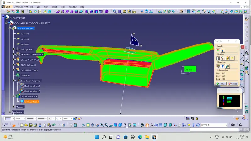
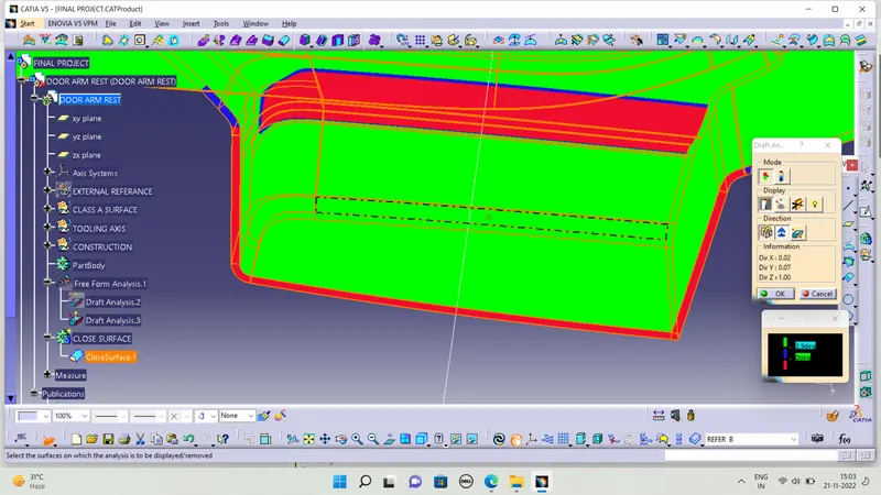
IN DOOR ARM REST THAT SURFACE ARE NOT CLEARED AND THEN CHANGE THE COMPOSS DIRCETION IT WAS CLEARED
Creating the Heat Stake:
Heat stalking is a pulsed- heat process to join two or more parts out of which one at least is madeof plastic .the plastic material using the heat and foam at a set process time. The bond is made by partially deforming the plastic part in order to fix the other. Heat stakes makes it easily to bond metal to plastic is commonly used in high volume and low cost application such as Automotive, IT and consumer appliances.
Step: 1
Creating the sketch by extracting the class A surface, by each surfaces separately, point and axis system created simultaneously on
the surface. Using positioned sketch.
Step: 2
The sketch feature is then extracted to the required dimension. And it is drafted for the 0.5 deg to the sliding tooling axis, it is filleted for
radius 0.25 of smooth edges as shown below.
Step:3
To transtalte the heat steake the whrer we want i using point to point translation command
The support rib as created, where the flange will come and sits to get arrested to the heat stake.
#RIBS
- The ribs provide economical stiffness and strength to the part without increasing the overall thickness of the part.
- The ribs are used as locating and arresting in the assembly as locators.
- Proper allignment in mating parts, slot and rib pair is long lasting other than screw pair which loosen up with time.
- Acting as stops or guide for mating the tilted headlamps.
- Rib designs includes.
- thickness, quantity, height , manufacturibility and location.
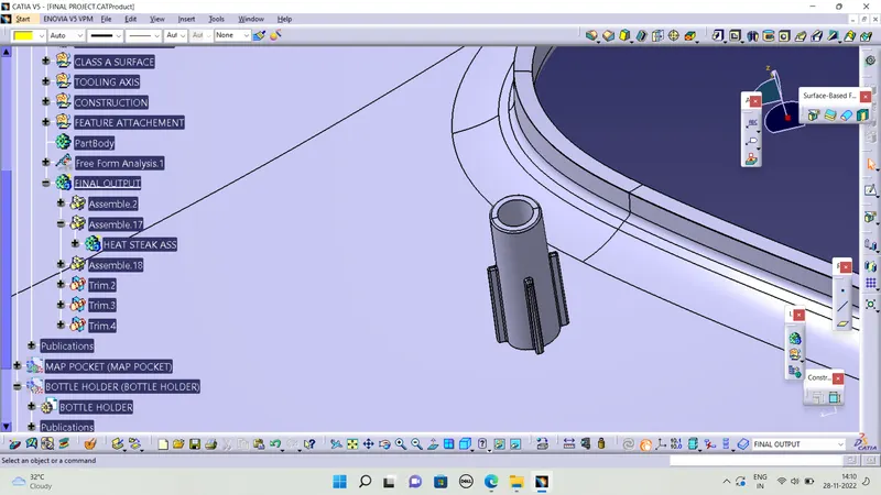
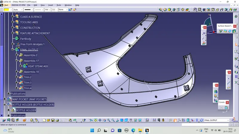
DRAFT ANALYSIS FOR HEAT STEAKE :
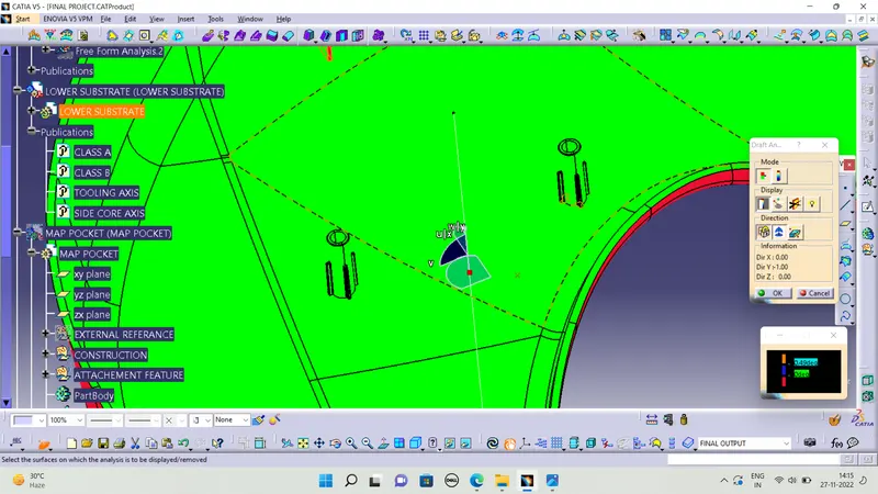
In heat steake i apply the 0.49 draft along main tooling axis
CREATING FLANGE :
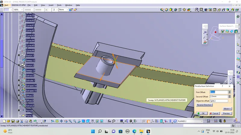
To flange is supporting feature to using with connect the two components i was simply extrct from the master section then sweep the extract line then goes to part workbench then thickneen the 2.5mm created the flange where we want
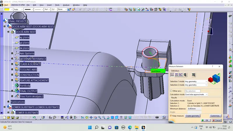
IN THAT FLANGE AND HEAT STEAK ARE MINIMUMDISTANCE FOLLWED 7 MM
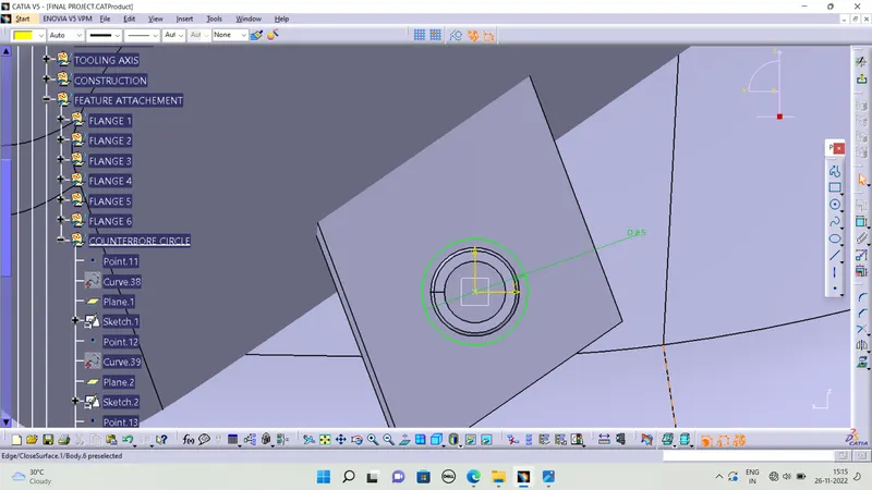
COUNTER BORE CIRCLE :
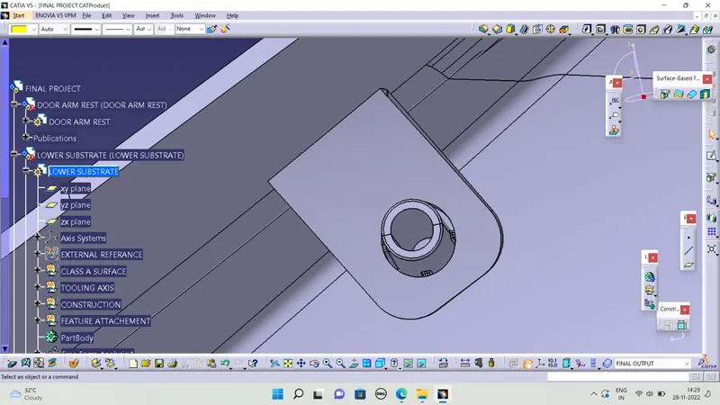
CREATING DOG HOUSE :
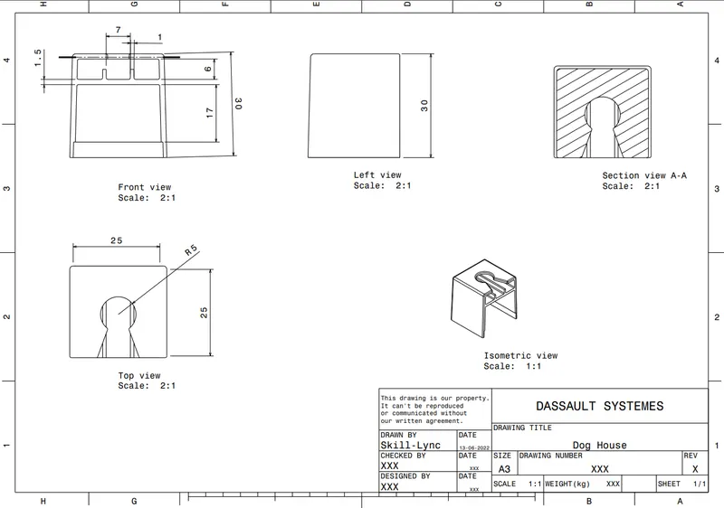
#DOG HOUSE
- Dog house is the attachment feature which helps you to assemble things at certain heights and also resolve the plastic defects.
- There are plenty dog house design which can be used for assembly purpose but we will be using the one provided to ous by the resources.
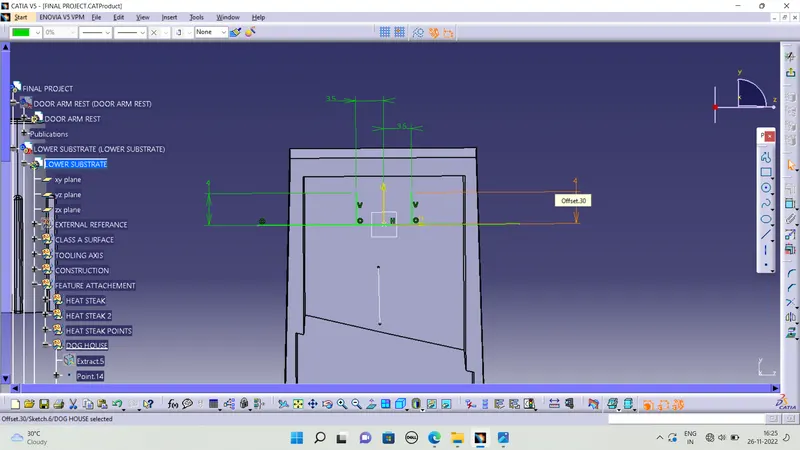
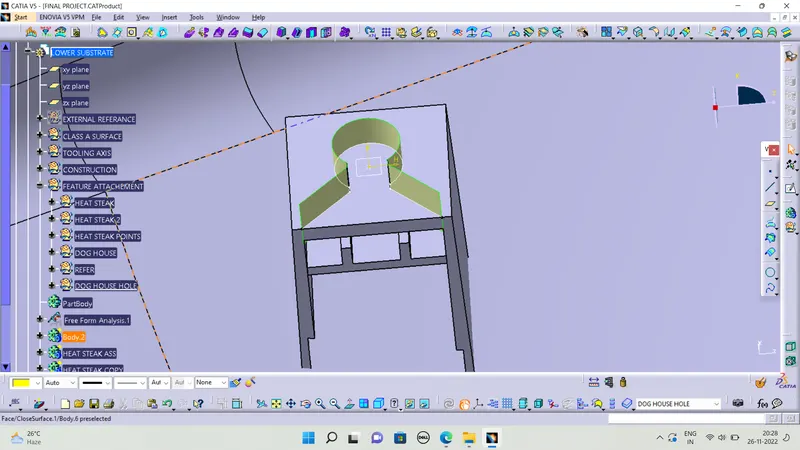
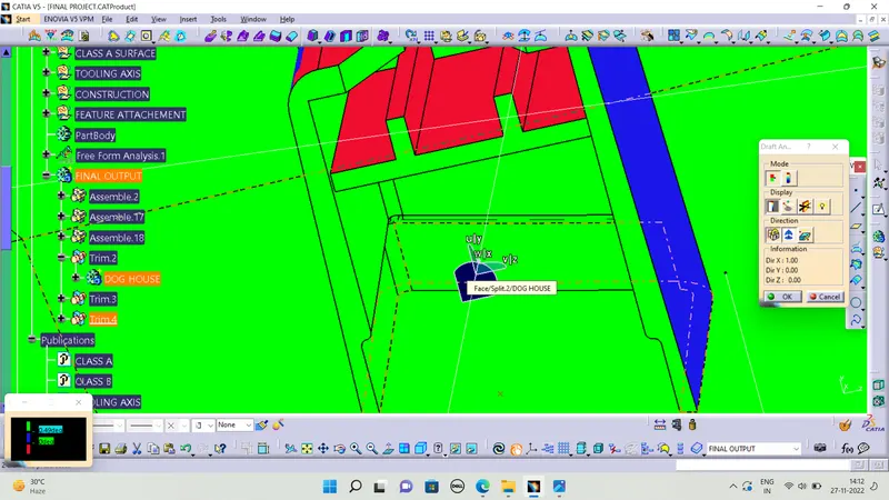
DRAFT ANALYSIS :
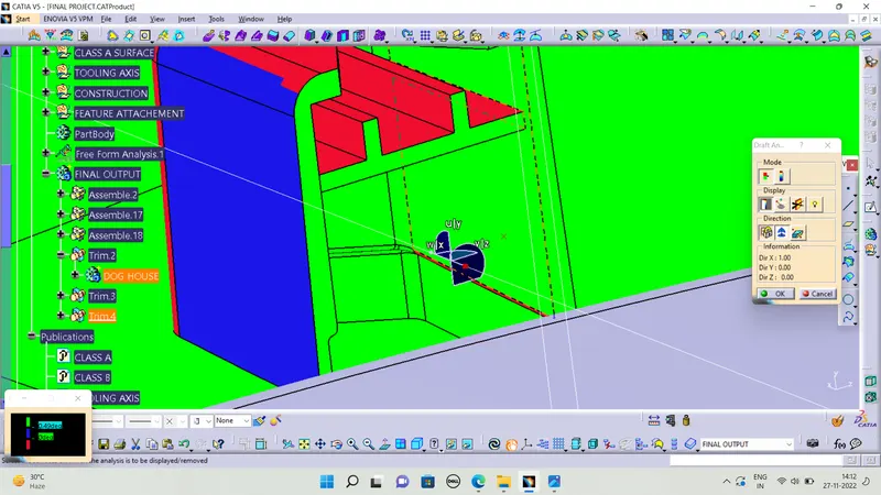
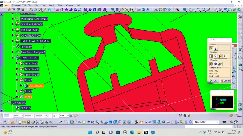
DRAFT FOR INSIDE RIBS 0.49 ALONG WITH SIDE CORE AXIS
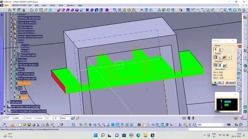
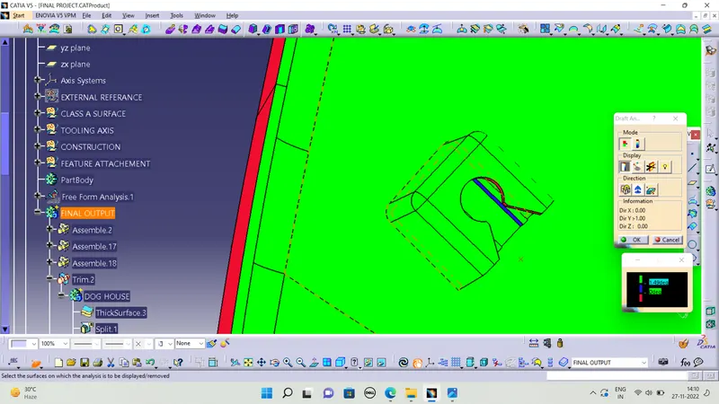
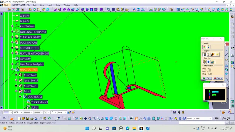
DOG HOUSE FACE WAS NOT CLEAR WITH DRAFT ANALYSIS:
PUSHPIN ASSEMBLY :
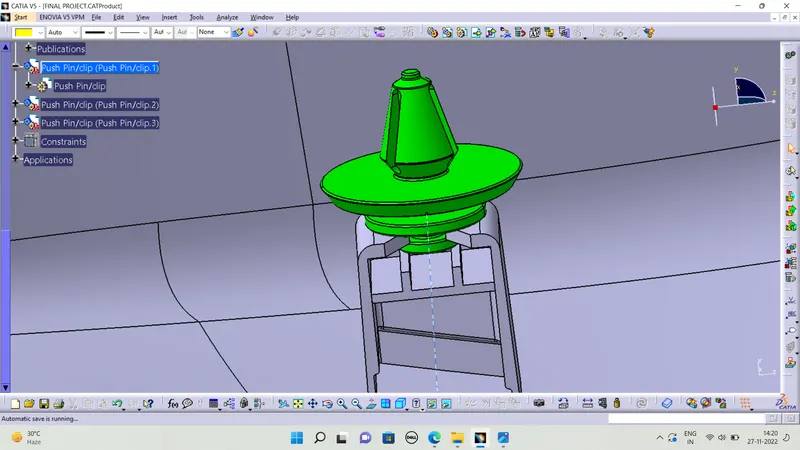
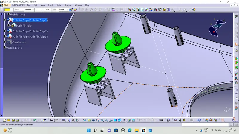
Pushpin is used to joint the plastic componet to sheet metal component it will assemble in assembly workbench using coincidence and face to face contact command to assemble the pushpin and dog house
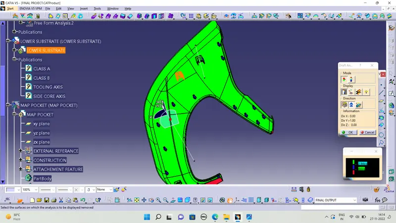
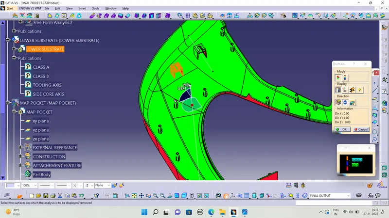
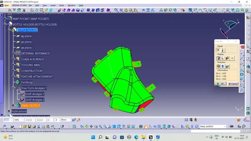
DRAFT ANALYSIS FOR FINAL OUTPUT OF ALL COMPONENTS :
LOWER SUBSTRATE :
MAP POCKET :
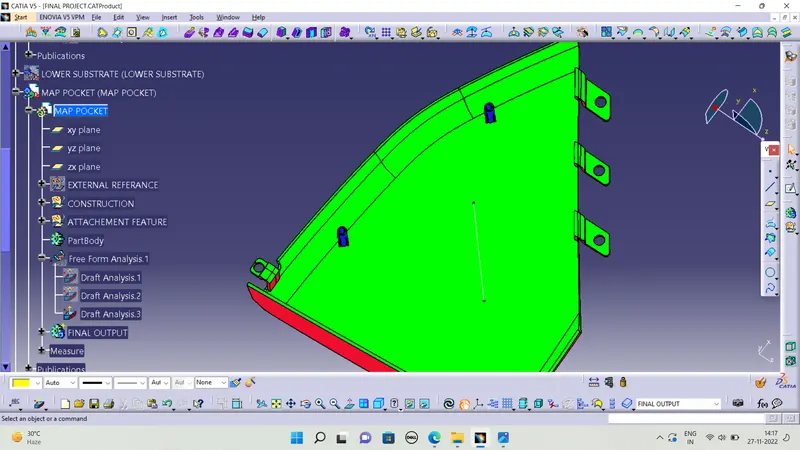
BOTTLE HOLDER :
DOOR ARM REST :
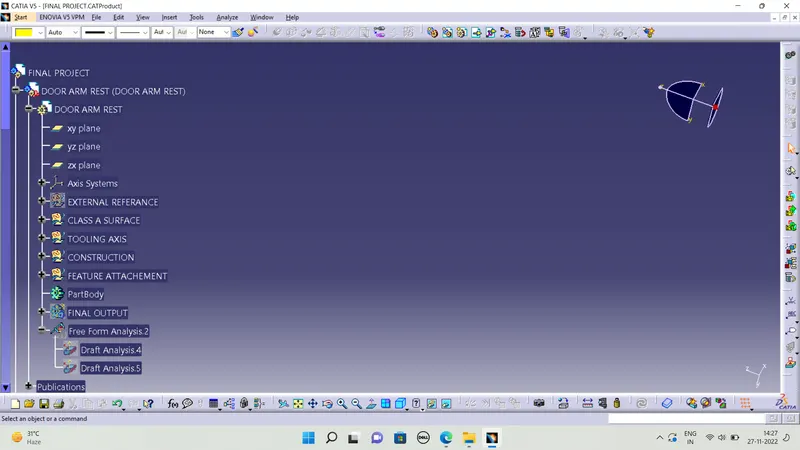
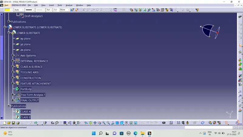
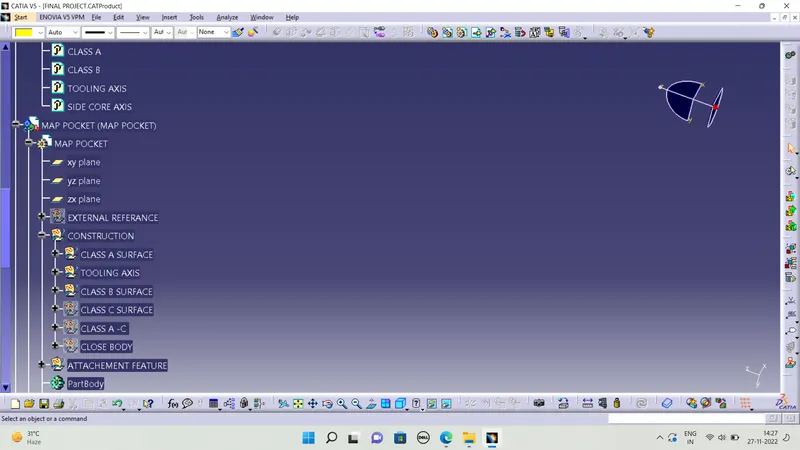
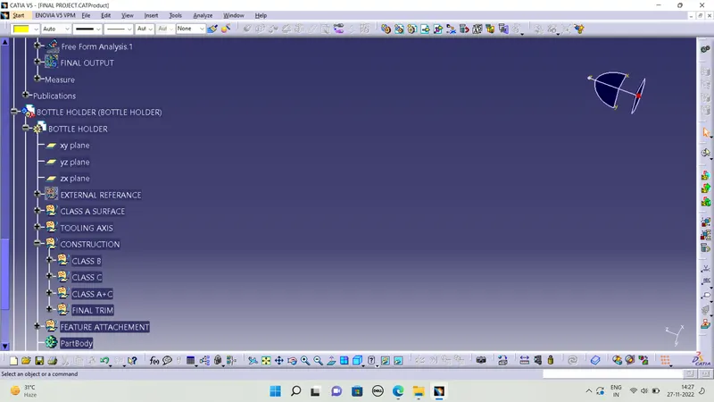
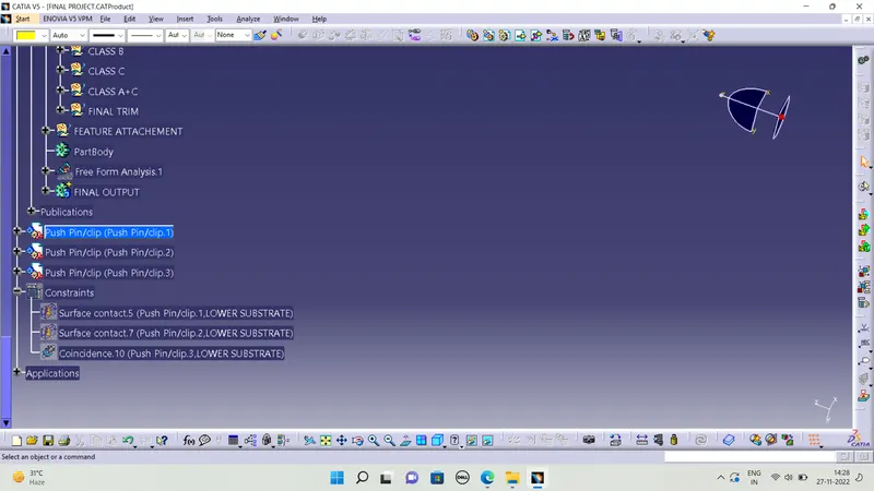
TREE STRUCTURE :
CONCLUSION:
CREATED CLASS B,C SURAFACE FOR ALL COMPONENTS THEN CREATED B FEATURE ATTACHEMNETS FOLLOWED OEM CONDITION IN ALL COMPONENTS THEN FINALLY PERFORMED WITH DRAFT ANALYSIS