Week 11 - Final project
Development of a Door Trim panel
Aim
To design and development of vehicle interior door trim using Catia V5 with given class A surface along with Master section and to create the side attachment features as per design rules.
Objective
- To create the thickened part using master section for reference.
- To create the mounting features as per design guidelines in the industry and with master sections.
- To perform draft analysis and tooling analysis.
Procedure
- Create a Single product file for all given parts by inserting each part separately with the help of Existing Component command.
1) Arm Rest
Tooling Axis
The axis in which the mold or core and cavity is opens or the axis which the designer can modify or create a model by taking axis as a reference is called Tooling Axis.
Procedure to create tooling axis.
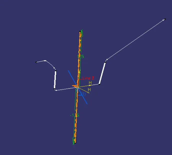
- Checking the Class A Surface, for to check which is the perfect place to create a tooling axis.
- By selecting the Arm rest as a reference surface creat a point at the centre of the surface.
- Create the intersection in xy direction and draw two lines on the plane.
- By Bisecting line 1 and line 2 with the point 1 we get the Tooling Axis and publish that tooling axis.
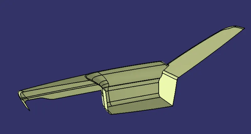
Create Class B Surface by offseting the class A surface
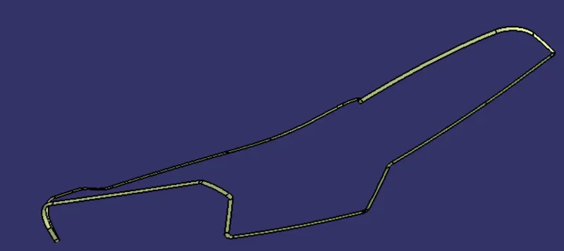
Create Class C Surface
- By using Multiple Extract , extract the class A surface and sweep it to an angle of 90 degree to the surface.
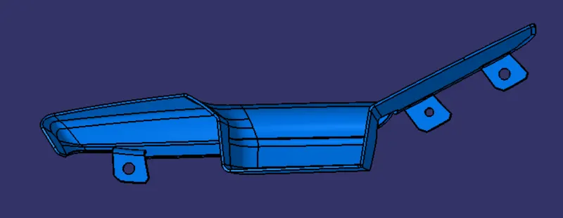
- After finishing all the 3 surfaces join the Class A and Class C surface together using join command. Now the joined surfaces are then trimmed with the Class B surface to form a Closed surface and create a flanges using master section.
Draft analysis
- In draft analysis of Arm rest we taking Arm rest Solid surface to draft.
Select the draft analysis tool in the tool bar and select Campass in the Direction option of the draft analysis tool. - Then move the campass on the tooling axis at draft direction and lock the draft direction.Useing the running pointer we see the draft angle of the Surface of the arm rest.
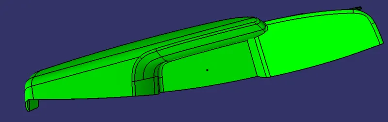
- Then by useing the color scale option we can change the Draft angle.The green color shows if the draft angle is more than 3 degree,red shows if the draft angle is between 0 to 3 and blue shows the negative draft angle.
2) Map Pocket
Tooling Axis
The axis in which the mold or core and cavity is opens or the axis which the designer can modify or create a model by taking axis as a reference is called Tooling Axis.
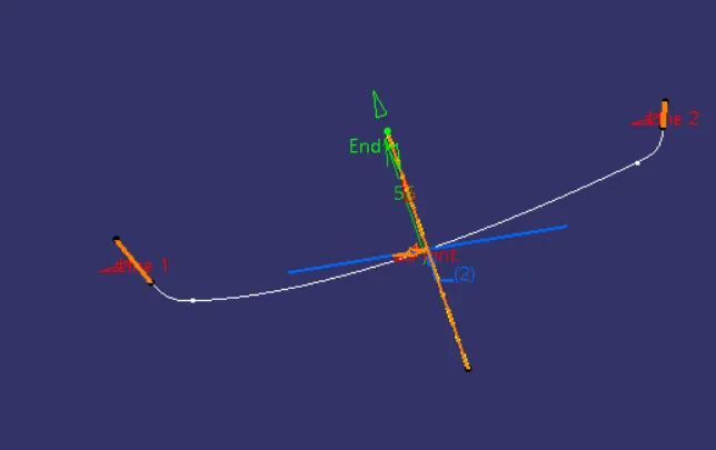
Procedure to create tooling axis.
- Checking the Class A Surface, for to check which is the perfect place to create a tooling axis.
- By selecting the Arm rest as a reference surface creat a point at the centre of the surface.
- Create the intersection in xy direction and draw two lines on the plane.
- By Bisecting line 1 and line 2 with the point 1 we get the Tooling Axis and publish that tooling axis.
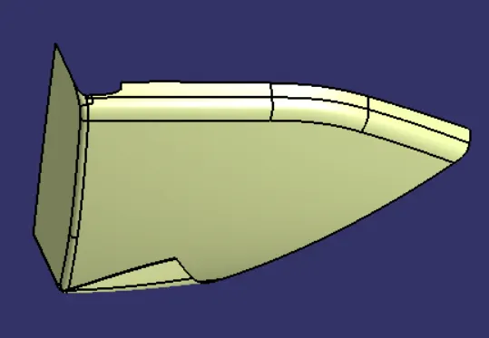
Create Class B Surface by offseting the class A surface
Create Class C Surface
- By using Multiple Extract , extract the class A surface and sweep it to an angle of 90 degree to the surface.
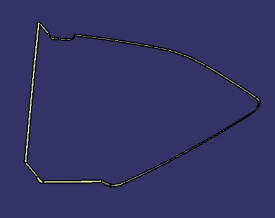
- After finishing all the 3 surfaces join the Class A and Class C surface together using join command. Now the joined surfaces are then trimmed with the Class B surface to form a Closed surface and create a flanges using master section.
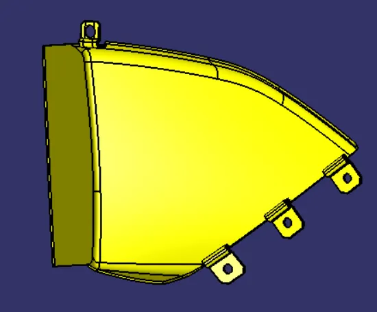
Draft analysis
- In draft analysis of map pocket we taking map pocket Solid surface to draft.
Select the draft analysis tool in the tool bar and select Campass in the Direction option of the draft analysis tool. - Then move the campass on the tooling axis at draft direction and lock the draft direction.Useing the running pointer we see the draft angle of the Surface of the map pocket.
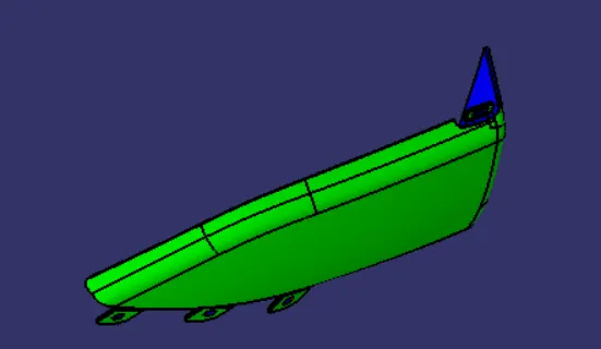
- Then by useing the color scale option we can change the Draft angle.The green color shows if the draft angle is more than 3 degree,red shows if the draft angle is between 0 to 3 and blue shows the negative draft angle.
3) Lower Substrate and Bottle Holder
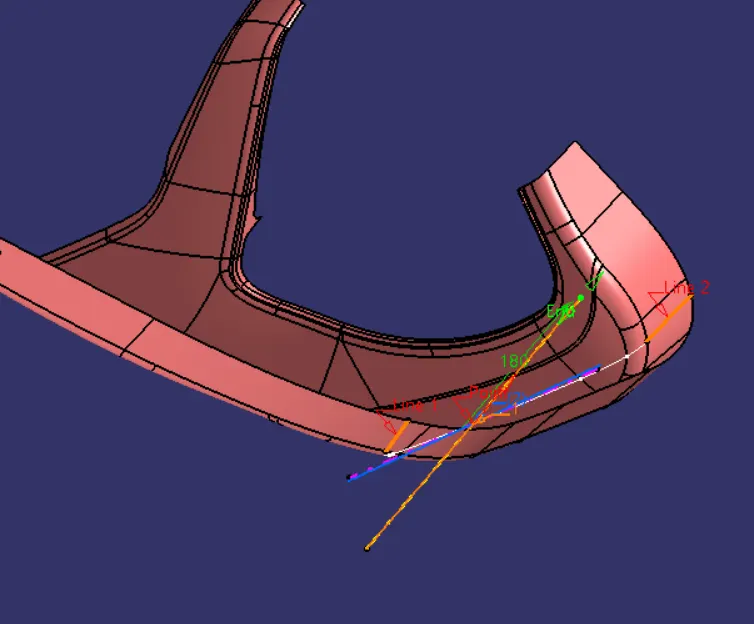
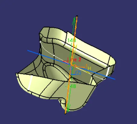
Tooling axis
The axis in which the mold or core and cavity is opens or the axis which the designer can modify or create a model by taking axis as a reference is called Tooling Axis.
- Lower Substrate
- Bottle Holder
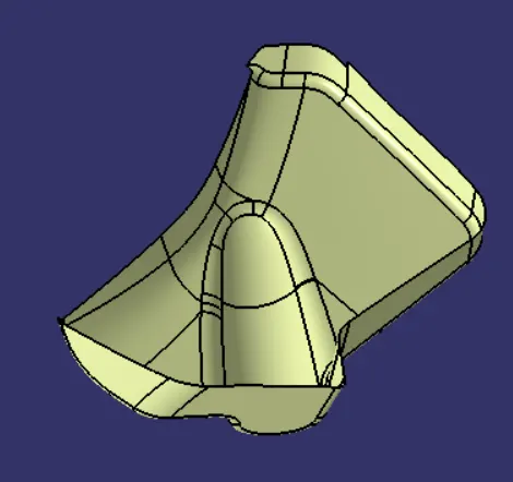
Class B Surface
Create Class B Surface by offseting the class A surface.
- Lower Substrate
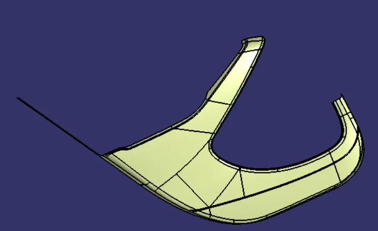
- Bottle Holder
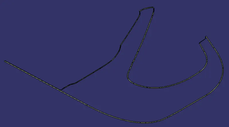
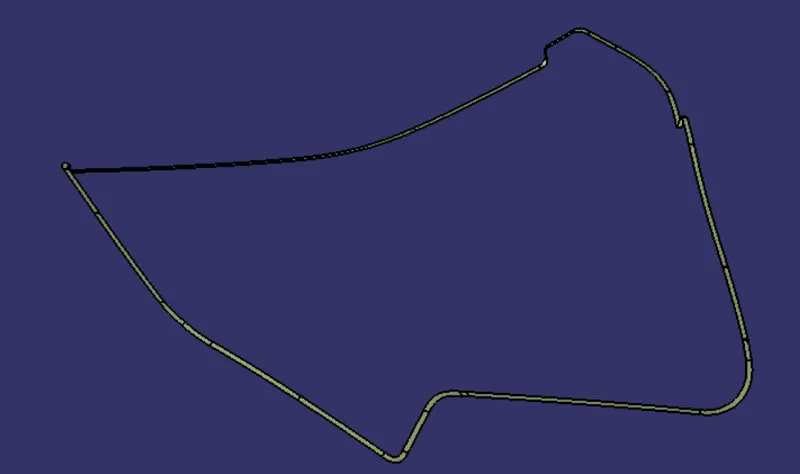
Class C Surface
By using Multiple Extract , extract the class A surface and sweep it to an angle of 90 degree to the surface.
- Lower Substrate
- Bottle Holder
Solid Surface
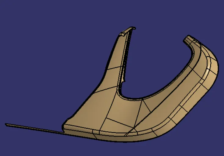
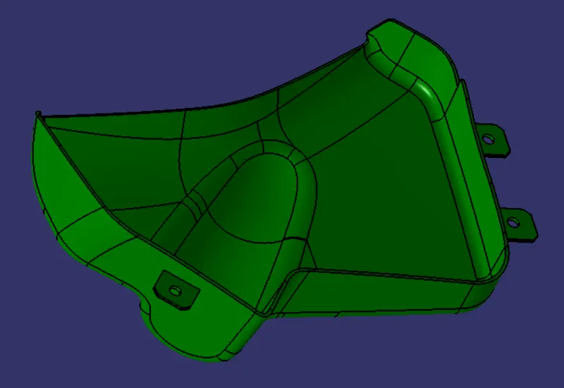
After finishing all the 3 surfaces join the Class A and Class C surface together using join command. Now the joined surfaces are then trimmed with the Class B surface to form a Closed surface and create a flanges using master section.
- Lower Substrate
- Bottle Holder
Draft analysis
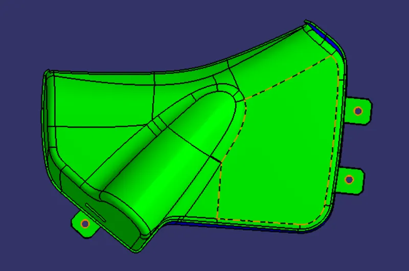
- Select the draft analysis tool in the tool bar and select Campass in the Direction option of the draft analysis tool.
- Then move the campass on the tooling axis at draft direction and lock the draft direction.Useing the running pointer we see the draft angle of the Surface of solid.
- Then by useing the color scale option we can change the Draft angle.The green color shows if the draft angle is more than 3 degree,red shows if the draft angle is between 0 to 3 and blue shows the negative draft angle.
- Lower Substrate

- Bottle Holder
Dog House
Dog house is designed to prevent the sink marks and to reduse the thickness of the mold.
Construction of Dog House
- To Create a dog house extract the surface from the solid door trim and create a point on the surface. Create a side core axis which is perpendicular to the tooling axis.
- By using positioned sketch draw the dog house and create outer walls by sweep the wall. And close the top wall using the extract and extrudeing the surface. Converting the walls to solid by useing thicksurface command , increase the thickness to 2 mm.
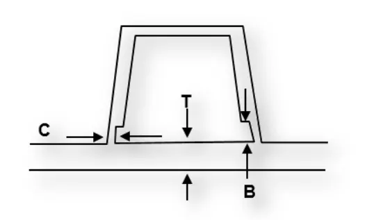
- Doghouse wall thickness at the intersection of the part wall ( C ) should be 40% or less than the main wall stock ( T ). The height of ( B ) should be between 3.0 – 6.0 mm according to the design rules.
C = 0.4 * T
C = 0.4 * 2.5
C = 1 mm
- I taken B value as 5 mm.
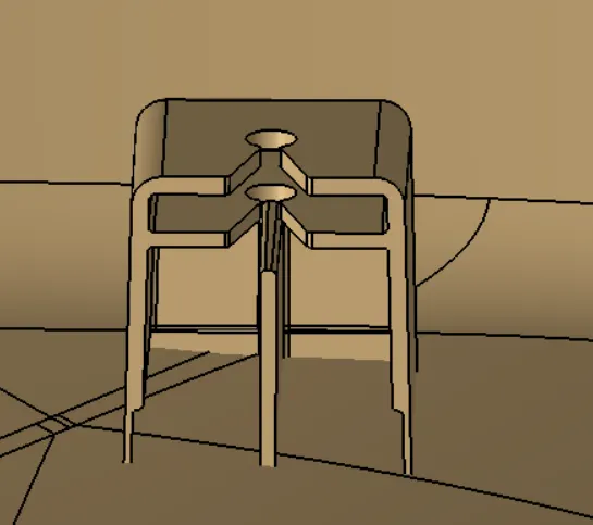
Draft analysis of Dog House
- In draft analysis of Dog House we taking Dog House Solid surface to draft.
Select the draft analysis tool in the tool bar and select Campass in the Direction option of the draft analysis tool. - Then move the campass on the tooling axis at draft direction and lock the draft direction.Useing the running pointer we see the draft angle of the Surface of the Dog house.
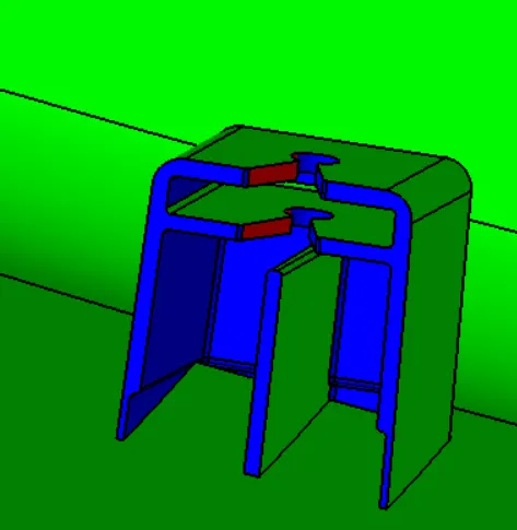
- Then by useing the color scale option we can change the Draft angle.The green color shows if the draft angle is more than 0.45 degree,red shows if the draft angle is between 0 to 0.45 and blue shows the negative draft angle.
Heat Stakes
Heat Stakes is used in the process of joining two dissimilar materials together and it is used to local heating and cooling to raise the temperature of plastic components and allow plastic reforming to be carried out.
Heat Stakes Design
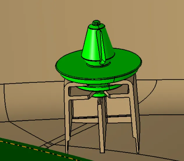
- Create two circles on the surface of the Door handle and pad to a hight h by considering the design rules, Height to Diameter Ratio - 3:1
h is calculated from the formula,
h = Wall thickness * 8
h = 2.5 * 8
h = 20 mm
- The Thickness - Typically 40%* of the nominal wall at the base is, w =0.4 * t
w = 0.4 * 2.5
w = 1 mm
- Draft the inside and outside with 0.5 degrees on the walls of boss and give the fillet value as 0.25 mm maximum radii.
- After createing one Heat Stakes , it is translated to the other direction useing coordinate system and to create stiffness to the Heat Stakes I created 4 supporting ribs to Heat Stakes .
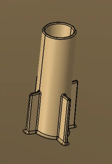
Draft analysis of Heat Stakes
- In draft analysis of Heat Stakes we taking Heat Stakes Solid surface to draft.
Select the draft analysis tool in the tool bar and select Campass in the Direction option of the draft analysis tool. - Then move the campass on the tooling axis at draft direction and lock the draft direction.Useing the running pointer we see the draft angle of the Surface of the Heat Stakes.
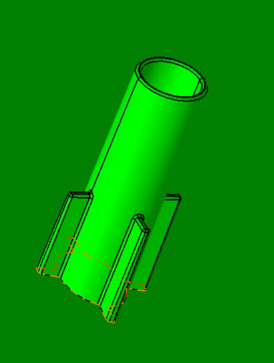
- Then by useing the color scale option we can change the Draft angle.The green color shows if the draft angle is more than 0.45 degree,red shows if the draft angle is between 0 to 0.45 and blue shows the negative draft angle.
Locators
Locators is a feature of arresting the component in the degrees of freedom is being assembled.
Construction of Locators
We construct the 4 way locators here. Extract the surface and create the point on the surface to create a plane.
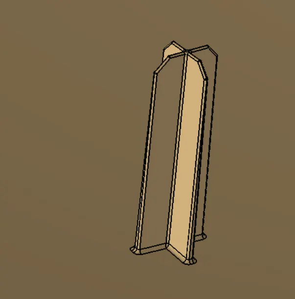
Using the plane, draw a sketch for 4 way and pad it along the tooling axis direction. Draft the locators for 0.5 degree and fillet of radius 0.25 mm and add chamfer of 2mm at an angle of 45 degree.
Draft Analysis of Locators
- In draft analysis of Locators we taking Locators Solid surface to draft.
Select the draft analysis tool in the tool bar and select Campass in the Direction option of the draft analysis tool. - Then move the campass on the tooling axis at draft direction and lock the draft direction.Useing the running pointer we see the draft angle of the Surface of the Locators.
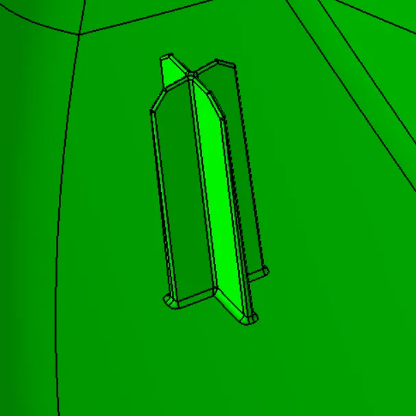
- Then by useing the color scale option we can change the Draft angle.The green color shows if the draft angle is more than 0.45 degree,red shows if the draft angle is between 0 to 0.45 and blue shows the negative draft angle.
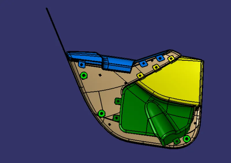
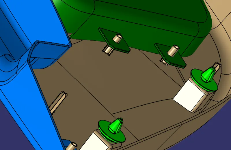
Final Product
Conclusion
The development of vehicle interior door trim using Catia V5 with given class A surface along with Master section and creation of the side attachment features as per design rules has been done.