Week 11 - Final project
DOOR ARM REST
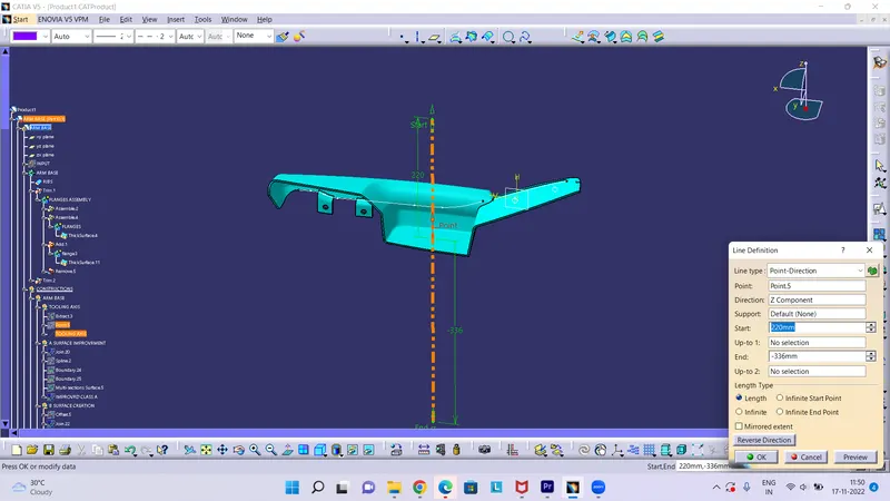
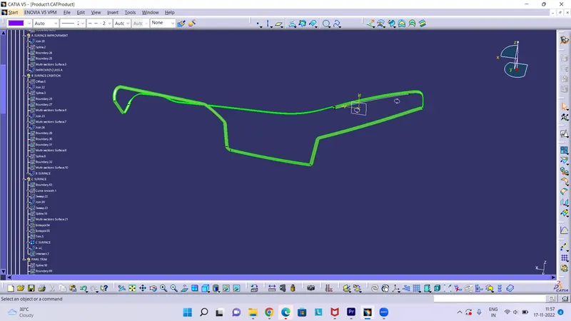
Tooling axis: - First we extract the lower surface than using point on surface at 0mm create a point. The line has been created using line command. The point direction command is used for create the line (Tooling Axis) along z direction.
IMPROVED CLASS A
CLASS A HAVE SOME PROBLEMS AND IT GOT IMPROVED
Creation of B surface
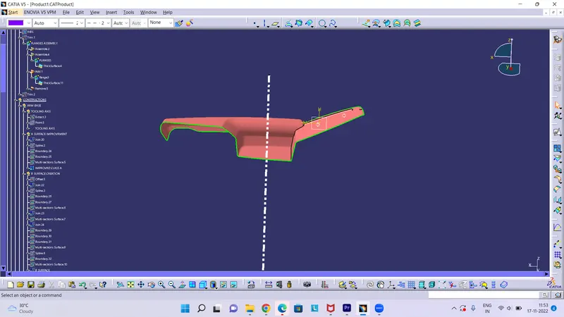
Class B surface has been created by offsetting the surface 2.5mm. Surface that are not offsetting were formed by using multi section command and join them.
Creation of C surface
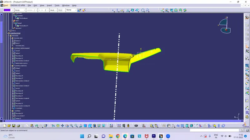
Using the multiple extract commands boundaries of class, A surface were extracted. Class C surface joins class A and Class B surfaces. It is created using the sweep command. Inputs for the sweep were extracted boundary, class a surface angle values and length of the sweep. Due to surface irregularities, it was not possible to make a single sweep. Hence several sweep and multi section were created, and finally they joined together to create a Class C surface.
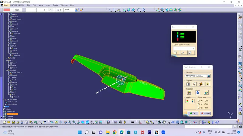
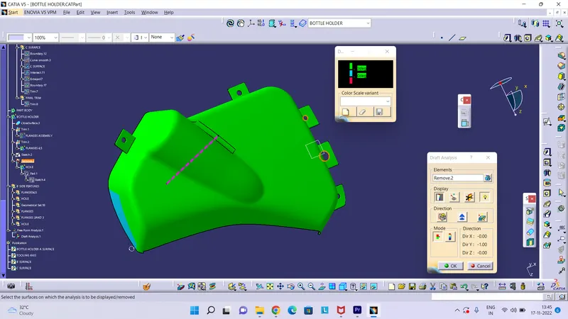
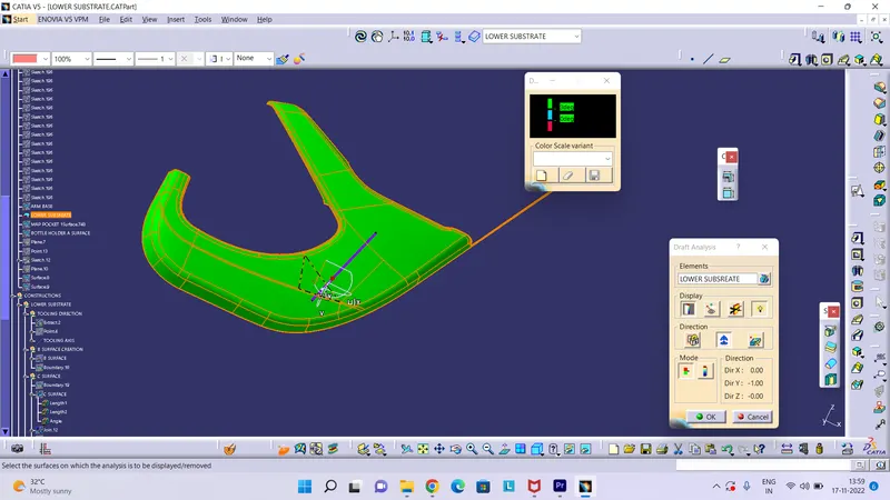
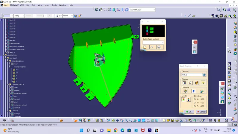
DRAFT ANALYSIS-
- Final plastic parts are the nominal draft angle is 3 degrees
- Insert< Analysis< Feature draft analysis
- First the compass is moved to the part which used to define the tooling axis new current draft direction then lock the draft direction using the lock icon.
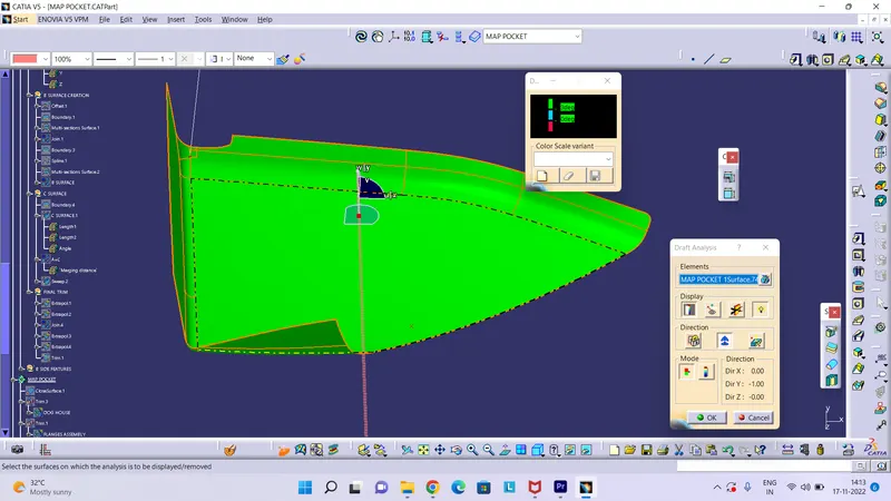
- The color of the chart indicates the draft if the color is indicated that means the part passes and used for further operation.
- By using the analysis under the running point icon, we can check draft angle at the various surface of the component.
- If the surface satisfied the draft angle, then it shows the green color if not appears in red color.
BOTTLE HOLDER
CREATION OF TOOLING AXIS
By extracting face and put a point .The line has been created using line command. The point direction option is used to create the main tooling axis in the Y direction.
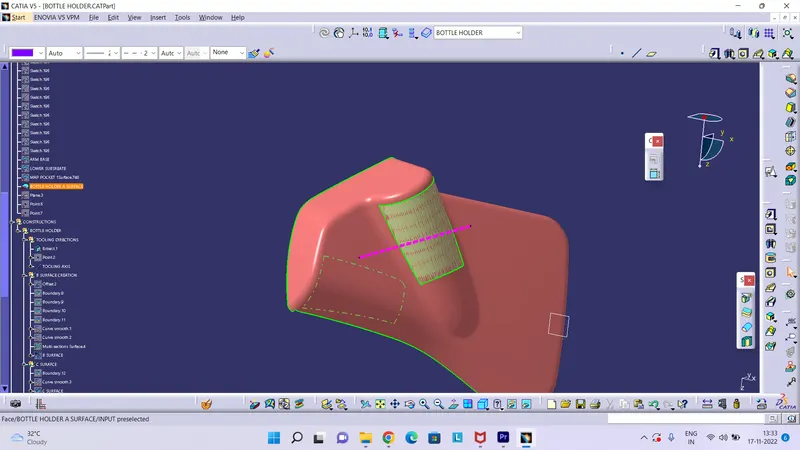
CREATION OF B SURFACE
Class B surface has been created by offsetting of class A surface. Offsetting has been done using offset class A 2.5mm distance .
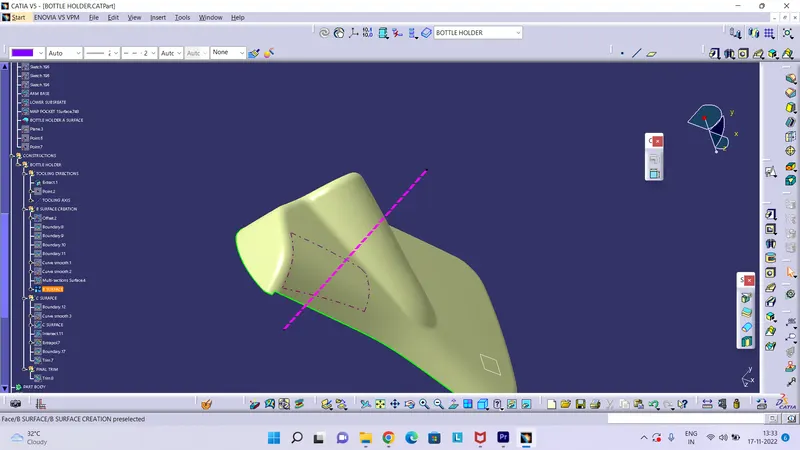
CREATION OF CLASS C SURFACE
Using the multiple extract commands boundaries of class, A surface were extracted. Class C surface joins class A and Class B surfaces. It is created using the sweep command. Inputs for the sweep were extracted boundary, class a surface angle values and length of the sweep. Due to surface irregularities, it was not possible to make a single sweep. Hence several sweep and multi section were created, and finally they joined together to create a Class C surface.
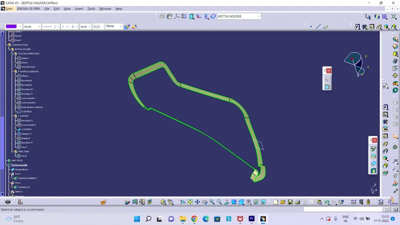
CLOSE BODY
Join the class c with class A. And trimmed with class b surface we get the closed surface.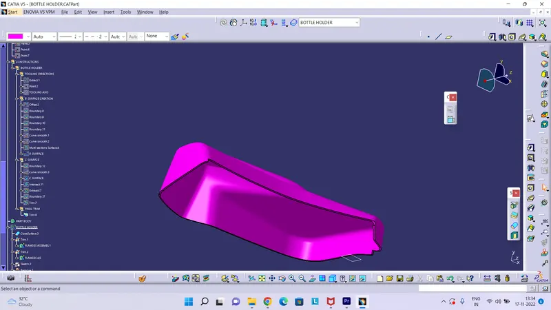
SOLID BODY
After joining the class, A and class C together, the join surface trimmed with class B surface to create a close surface. Some errors showing that’s why we extrapolate the class B surface for correctly trim the class A and C with class C.
Go to part workbench insert a body and doing close surface operation create the solid body.
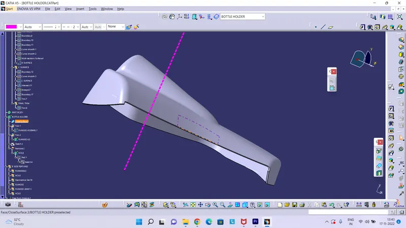
DRAFT ANALYSIS OF FINAL COMPONENT
LOWER SUBTRACT
TOOLING AXIS
Create a point on surface 0mm.The line has been created using line command. The point direction option is used to create the main tooling axis in the Y direction.
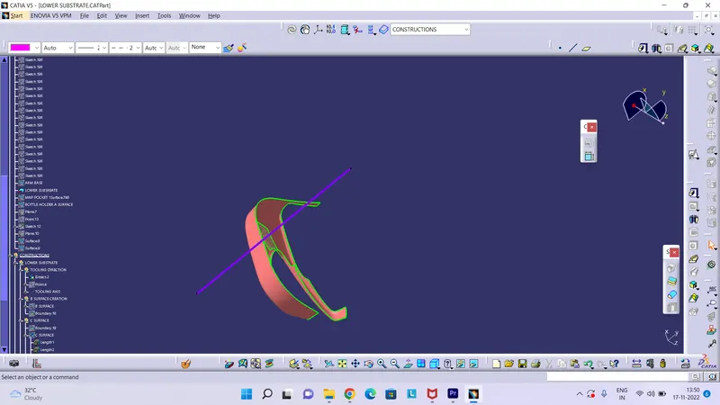
CREATION OF CLASS B SURFACE
Class B surface has been created by offsetting of class A surface. Offsetting has been done using offset class A 2.5mm distance.
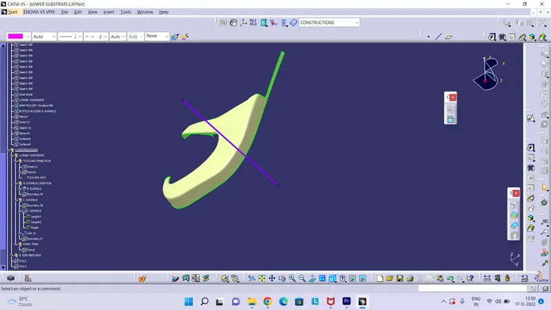
CREATION OF CLASS C SURFACE
Using the multiple extract commands boundaries of class, A surface were extracted. Class C surface joins class A and Class B surfaces. It is created using the sweep command. Inputs for the sweep were extracted boundary, class a surface angle values and length of the sweep. Due to surface irregularities, it was not possible to make a single sweep. Hence several sweep and multi section were created, and finally they joined together to create a Class C surface.
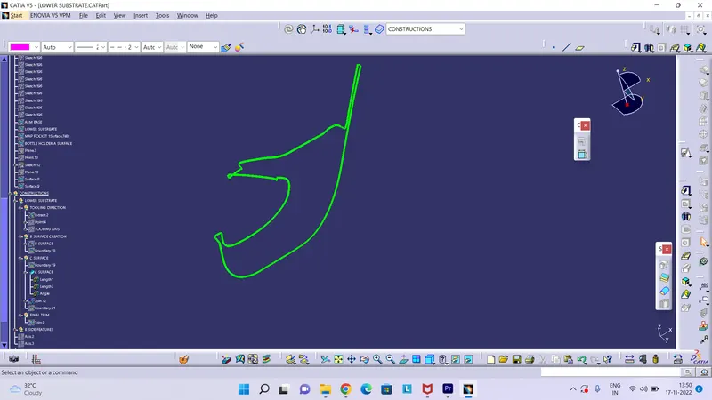
CREATION OF CLOSE BODY AND SOLID BODY
Join the class c with class A. And trimmed with class b surface we get the closed surface.
After joining the class, A and class C together, the join surface trimmed with class B surface to create a close surface. Some errors showing that’s why we extrapolate the class B surface for correctly trim the class A and C with class C.
Go to part workbench insert a body and doing close surface operation create the solid body.
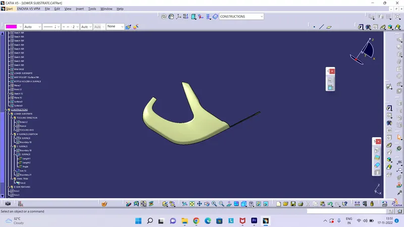
DRAFT ANALYSIS OF CLASS A
MAP POCKET
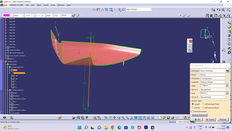
CREATION OF TOOLING AXIS
The tooling axis created using line command. The point -direction option used to create line.
CREATION OF CLASS B
Class B surface has been created by offsetting of class A surface. Offsetting has been done using offset class A 2.5mm distance.
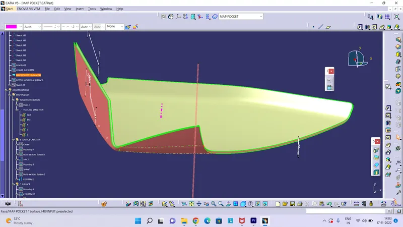
CREATION OF CLASS C
Using the multiple extract commands boundaries of class, A surface were extracted. Class C surface joins class A and Class B surfaces. It is created using the sweep command. Inputs for the sweep were extracted boundary, class a surface angle values and length of the sweep. Due to surface irregularities, it was not possible to make a single sweep. Hence several sweep and multi
section was created, and finally they joined together to create a Class C surface.
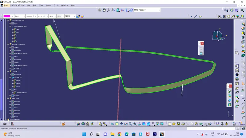
CREATION OF CLOSE SURFACE
Class A and Class C surface are joined together, trim with class B and create close surface. And the close surface converted into close body.
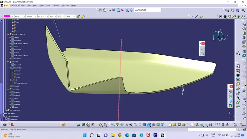
DRAFT ANALYSIS
PUSH PIN
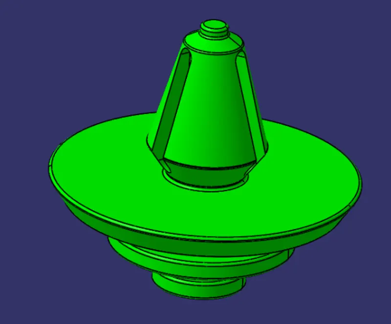
Push pin which helps us locating and arresting component of an assembly and it provides alignment in matting parts and also acts as various guide of mechanism.
CREATION OF ENGINEERING FEATURES
FLANGE-Flange are needed to join different component together, so I have to create flange as design guidelines of master section given as the input basically the measurement and location of the flange.
RIBS- Ribs provide a means to economical stiffness and strength in molded parts without increasing overall wall thickness. They also facilitate:
1) Locating & arresting components of an assembly.
2) Providing alignment in mating parts.
3) Acting as stops or guides for mechanisms.
DOG HOUSE
Dog house is an engineering feature used in plastic trim design. The primary function of a dog house is to avoid sink marks on the class A surface which may occur due to features such as a thick screw boss or rib on the backside of Class A. So, the best possible solution is to increase the height and decrease the cross-sectional thickness of the ‘legs’ by using a dog house. We can also use them for solving the necessity of large length features such as a screw boss which may require a large length sometimes. We can use a dog house and make a screw boss above it in such situations. We can also use them for making features that are perpendicular to the main tooling direction.
HEAT STAKES
Manufacturing operations currently use many different combinations of attachment methods to keep components together. Common fasteners such as bolts, screw, and rivets can be used to form permanent attachments, but there are attachment methods that don’t require secondary hardware. One of those methods is heat staking which does not require additional fasteners.
REASONS FOR HEAT STAKING-
- Multiple staking shapes for different benefits.
- Excellent durability
- No extra materials are needed
- Increased efficiency
- Easy maintenance.
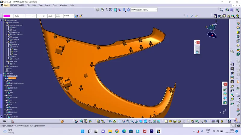
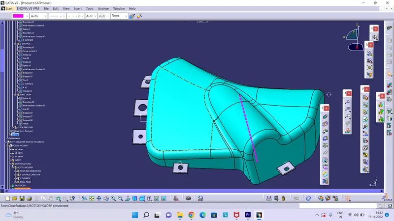
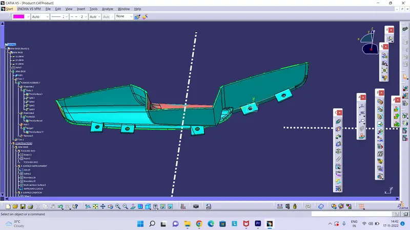
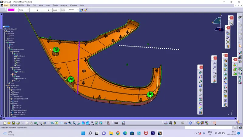
FINAL COMPONENTS WITH B SIDE FEATURES
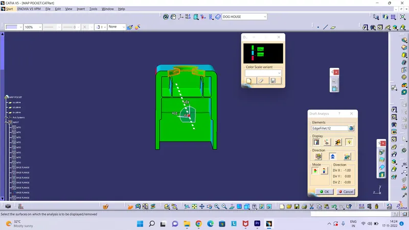
DRAFT AANALYSIS OF DOG HOUSE WITH TOOLING AXIX AND SIDE CORE