Week 11 - Final project
FINAL PROJECT - Development of a Door Trim panel
I Have completed the final project in the following way-
at first, I inserted the same CAD file (provided in this challenge) in the Assembly design for four-time and renamed them according to the part name( i.e i) Arm Rest ii)Lower subtract iii)Map pocket iv)Bottle Holder) and in each separate part, I have hidden the remaining parts (for example if I am working on the armrest cad part then I have hidden lower subtract, map pocket, and bottle holder)
CREATION OF TOOLING AXIS
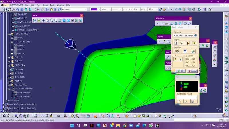
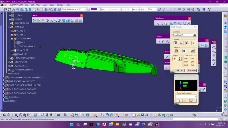
For every component in the door trim i have used the same method of creating the tooling axis i.e selecting the flat surface and inserting the point overthat and again inserting the line over that point and extending it to the required the length and then do the draft analysis for that class a surface and check whether the component will turn into complete green on colour i.e draft of 2.9 degrees.
and the created line is known to be tooling axis
CREATION OF CLASS B SURFACE If I am working on the armrest, then I have created the class b surface of the armrest by offsetting the class a surface of the armrest with 2.5mm and then I got some patches and worked on that patches. I have completed the class b surface of the armrest by removing the filleted areas and extrapolating the flat surfaces and then trimming them and again applying the fillet to that surface from the class a surface,
CREATION OF CLASS C SURFACE
After the successful creation of the class b surface we have to work on the class c surface, have created the class c surface from the class a surface ( by sweep option).
CREATION OF CLOSED BODY
After the successful creation of class A and class B surfaces, we have to apply the trim option for a complete close body and then got to the part workbench, and then apply the close body command to it.
In the same way, mentioned above, I've created all the remaining parts from the class A surface to the final close body.
After the successful creation of a closed body of armrest, lower subtract map pocket and bottle guard. we have to work on the creation of Flanges, Heat stakes, Dog houses, and Locators.
CREATION OF FLANGES
For the creation of flanges, I selected a point on the curve and inserted the plane which is perpendicular to the curve and drew a 2d flange in a sketch and extruded the 2d sketch to the required dimensions then I have applied the thick option over that a 2.5mm and then from boolean operation I have union trimmed the unwanted portion from that and joined it to the main part body
By translating command I have translated the present flange to the required area and in a few other areas, I have created the flange separately.
CREATION OF HEAT STAKES
To create the heat stake, at first I extracted a single surface from the class b surface and inserted the point and plane over that. I have sketched the 2 circles with the given reference diametres from the parent body and then I pad them to the required length for the creation of ribs to the heat stakes i inserted the plane which is perpendicular to the heat stake body and then sketched the 2D ribs and then I have extruded that 2 d sketch to the part body by applying thick option to 1.5 mm and then I untrimmed the unwanted rib portion from the heat stake. then I again used the boolean operation called unitrim to remove unwanted material from the heat stake to the main final body.
After successful creation of heat stake i have translated the same heat stake to all required locations
i have also created the holes in the flanges i to insert the heatstakes
so the heat stakes are arranged according to the holes provided in the hat stakes.
CREATION OF LOCATORS
A simple locators are created by inserting two lines and and then i extruded it to the required length and and i applied thicken option to that extruded surface and then i edge filleted it.
after successful creation of locators i again used boolean operation called unitrim to delete unwanted material from the main part body
INSERTION OF PUSH PIN INTO PRODUCT PART
The push pin which is already provided by the challenge is been constrained to the hole provided at the top of the dog house
i have created the axis for the both dog house hole and push pin bottom circle surface and then i made axis constrain to both of them
and again i given surface constrain to the both dog house and push pin
NOTE :- I HAVE DRAFTED THE HEAT STAKES. RIBS AND DOG HOUSE WALLS TO 0.5 DEGRRES
DOG HOUSE
DRAFT ANALYSIS OF DOG HOUSE WITH RESPECT TO TOOLING AXIS
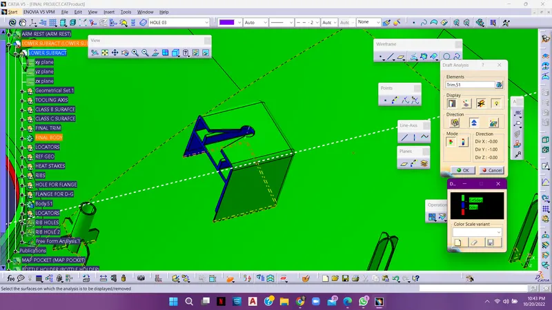
DRAFT ANALYSIS OF DOG HOUSE WITH RESPECT TO SIDE CORE TOOLING AXIS
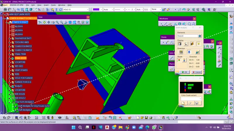
DRAFT ANALYSIS OF LOWER SUBTRACT
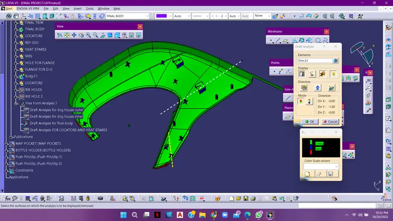
DRAFT ANALYSIS OF LOCATORS
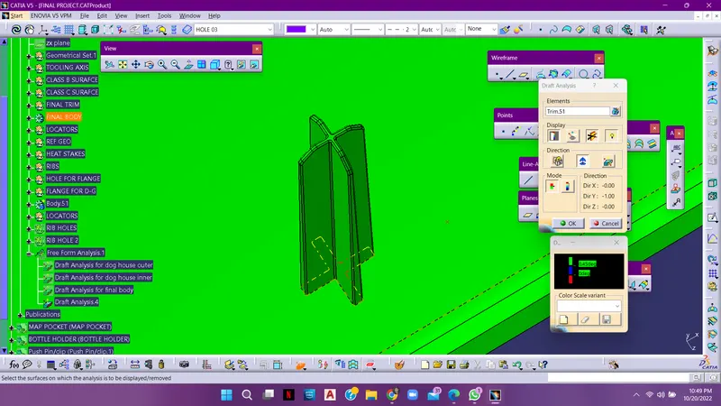
DRAFT ANALYSIS OF THE HEAT STAKES
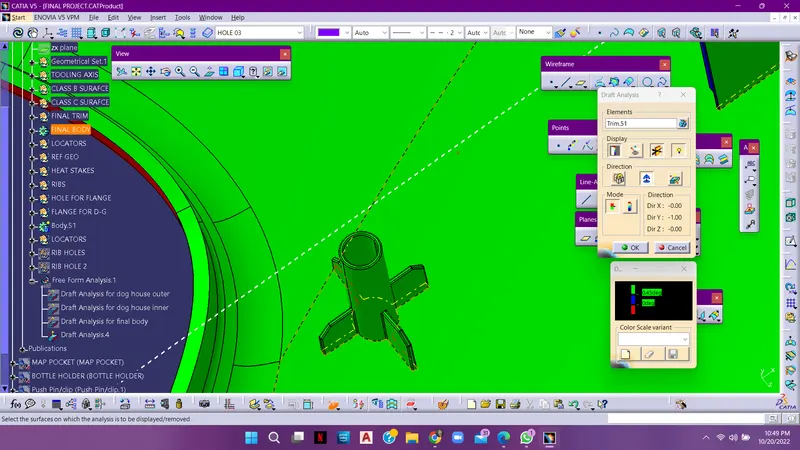
DRAFT ANALYSIS OF ARM REST
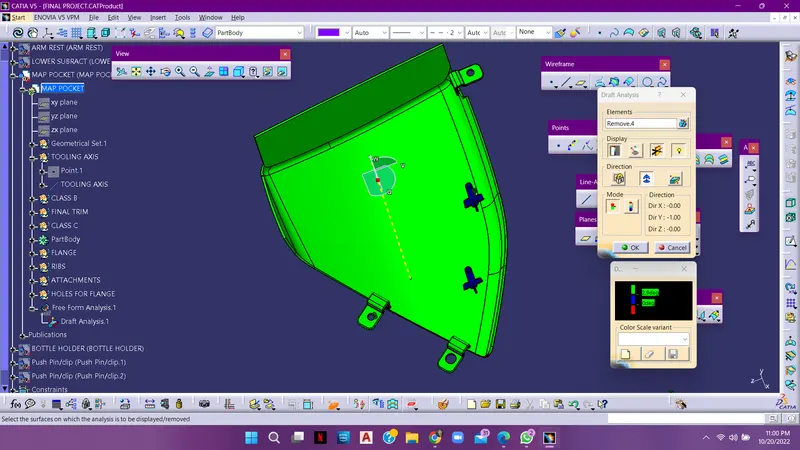
DRAFT ANALYSIS OF MAP POCKET
DRAFT ANALYSIS OF BOTTLE GUARD
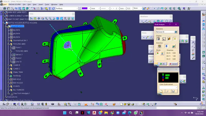
in above figure is shows some areas in blue colour, it indicates that there is draft less than 2.6degress
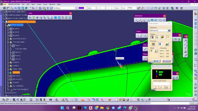
DRAFT ANALYSIS OF BOTTLE GUARD CLASS A SURFACE