Design Door Panels
AIM:- To develop a door trim panel
INTRODUCTION:-
Door panels serve as an interface between the interior of the car and the inner workings of the door, and between vehicle occupants and the door. They are expected to meet a variety of design specifications regarding safety, aesthetics, and functionality. In addition, they are expected to continue the material theme of the dashboard and pillars while concealing intricate electrical and mechanical components for operating locks, windows, and other features. The door panel has evolved from a simple two-part system of latch and simple winding mechanism to a more sophisticated enclosure. Doors currently have an inner full-width panel consisting of electronic windows, central locking system, and speakers. These panels typically consist of a foamed core covered with either textiles or plastics.
Automotive Plastic Trim:-
The design of Automotive Interior and Exterior plastic components is called Trims. The plastic components that you see inside the car are Interior. Ex: Dashboard, Instrument Panel, Doors, seating, and pillars. Plastic components that you see outside of a car are Exterior. ex: bumper, light assembly, hoods.
Door Trim:-
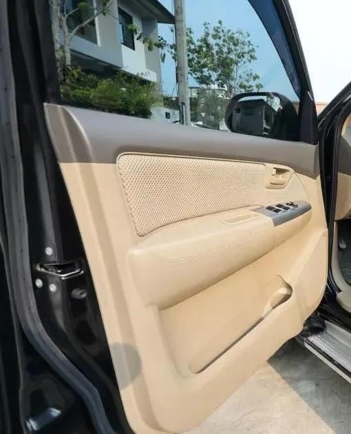
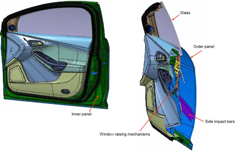
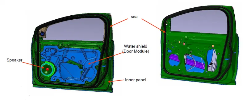
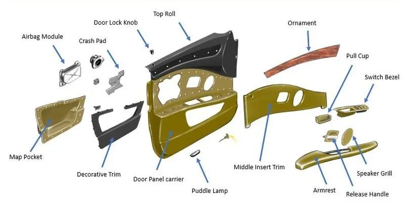
The door panel covers internal parts like the window regulator, the power window motor, and the wiring. It is attached to the sheet metal part of the door. It is designed differently based on the design of the sheet metal part of the door. Besides its aesthetic look, it also has many functional features attached to it such as an armrest, bottle holder, speaker attachment, etc. In older cars, door panels used to be made out of cardboard and upholstered with material that matches the rest of the upholstery within the cabin. On the other hand, most modern cars have door panels made from plastic. The main materials used include kenaf, which grows year-round and has excellent CO2 absorbing properties, and plant-derived plastic, making them environmentally friendly as well.
 DOOR ARM REST:-
In the front of the car, a central armrest, which commonly folds away based on user preference, will also often include a storage compartment and sometimes even cup holders. Some also provide the location for controls for non-essential functions of the vehicle, such as climate control or window motors.
DRAFT ANALYSIS:
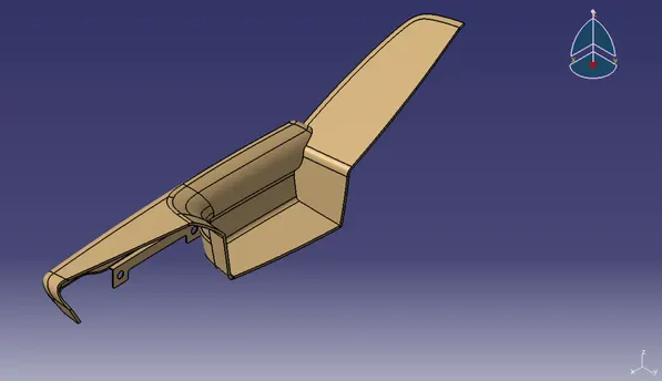
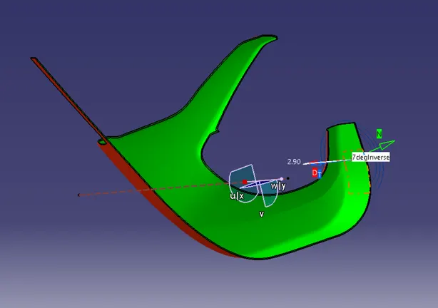
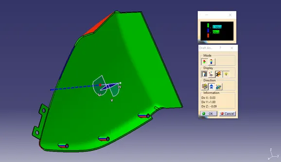
The draft analysis command enables you to detect if the part you drafted will be easily removed. This type of analysis is performed based on color ranges identifying zones on the analyzed element where the deviation from the draft direction at any point, corresponds to specified values.
- This type of analysis is performed based on color ranges identifying zones on the analyzed element where the deviation from the draft direction at any point, corresponds to specified values.
These values are expressed in the unit as specified in tools >option > general > parameters > unit tab.
You can modify them by clicking on their corresponding arrow or by entering a value directly in the field. - The mapping texture accuracy depends of the video card used. Therefore, colors displayed on surfaces could be wrong according to the color scale, when the value displayed on the fly is right because the analysis is recomputed at the cursor location.
Sometimes, in the case of extremely closed values, it is recommended to switch to the quick mode to improve the color display accuracy. - The maximal draft analysis accuracy is 0.01 deg. According to the graphic card performance, this accuracy can be debased.
- The different mapping analyses of the same surfaces cannot be displayed simultaneously, even if you have set the mapping analyzes in no show. You need to visualize them one after the other.
PROCEDURE TO PERFORM DRAFT ANALYSIS
1.Select a surface.
2.Click the (feature) draft analysis icon:
3.Double-click on the value in the color scale to display the value edition dialog box.
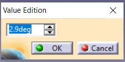
a)Enter a new value (negative values are allowed) to redefine the color scale, or use the slider to position the distance value within the allowed range, and click OK
b)The value is then frozen, and displayed in a green rectangle.
c)The color scale settings (colors and graduated values) are saved when exiting the command, meaning the same settings will be applied when you will edit a draft analysis. New settings are created with each new draft analysis.
d)When the draft angle value of the surface is equal or smaller than a graduated value, the color below the graduated value is applied.
e)When the draft angle value of the surface is greater than the greatest graduated value, the color above this graduated value is applied.
4.Exit the dialog box.
5.Click the light effect button and the colors of the analyzed elements react to the light source.
6.Click the inverse button to automatically reverse the draft direction.
7.Once you have finished analyzing the surface, click OK in the draft analysis dialog box.
a)Note that settings are saved when exiting the command, and redisplayed when you select the draft analysis icon again.
b)Be careful, when selecting the direction, not to deselect the analyzed element.
c)A draft analysis can be performed just as well on a set of surfaces.
d)If an element belongs to an analysis, it cannot be selected simultaneously for another analysis, you need to remove the current analysis by deselecting the element to be able to use it again.
e)In some cases, even though the rendering style is properly set, it may happen that the analysis results are not visible. Check that the geometry is up-to-date, or perform an update on the involved geometric elements.
f)The analysis results depend of the current object. May you want to change the scope of analysis, use the Define in Work object contextual command.
LOWER SUBSTRATE:-
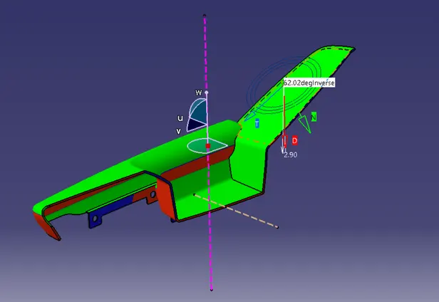
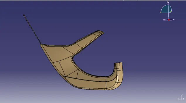
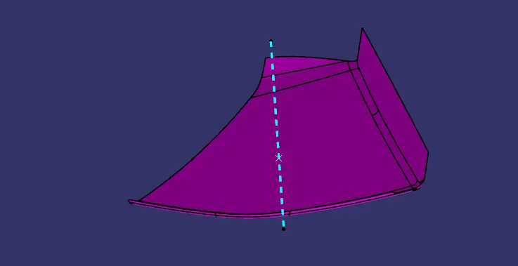
Multiple extracted the subparts of the surface for lower substrate and using join command created a single class A surface. Some parts were not properly aligned so by joining command and sub-elements to remove that part and using multi-section surface to create a class A surface with no defects.
- Create a point on the class A surface to move the main tool for component creation on the base surface.
- Mask an axis over the point created with the same directions as the main axis
 .
. - Using Intersect command from Generative Shape design select the YZ plane as the first element and the class A surface as the second element
 .
. - After creating the intersecting lines select the Line command and join the vertices which show the most possible draft angle manufacturable.
- Bisect those two lines over the axis point we created

Draft analysis:
- After Tooling Axis Select the Feature Draft Analysis option from the Insert Option
 .
. - Select the element to analyze.
- Next click on Use the compass to define the new current draft direction option and make it align with the tooling axis by dragging it to the axis
 .
. - If the color appears blue just click the invert option on the right side of the draft direction axis button
INNER MAP POCKET:-
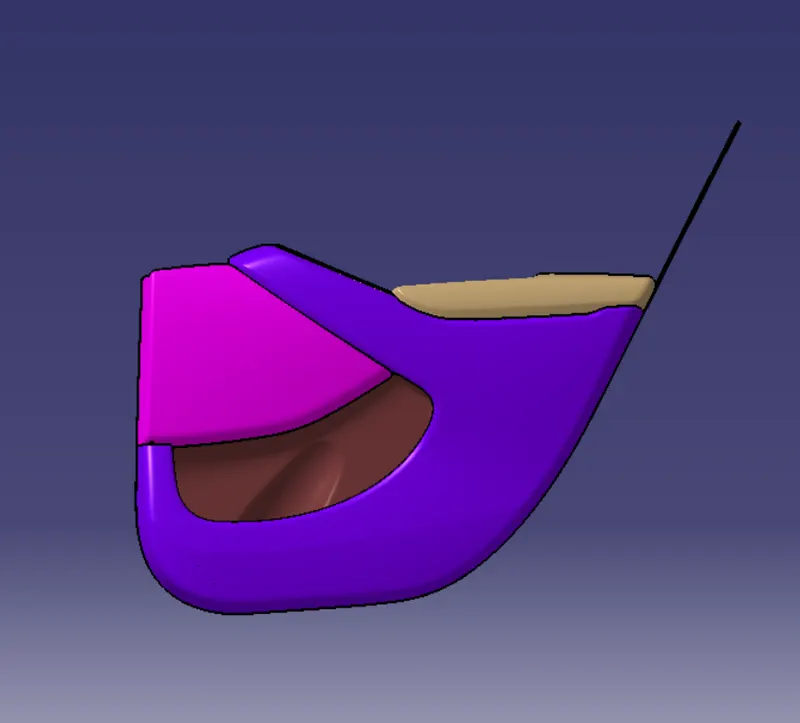
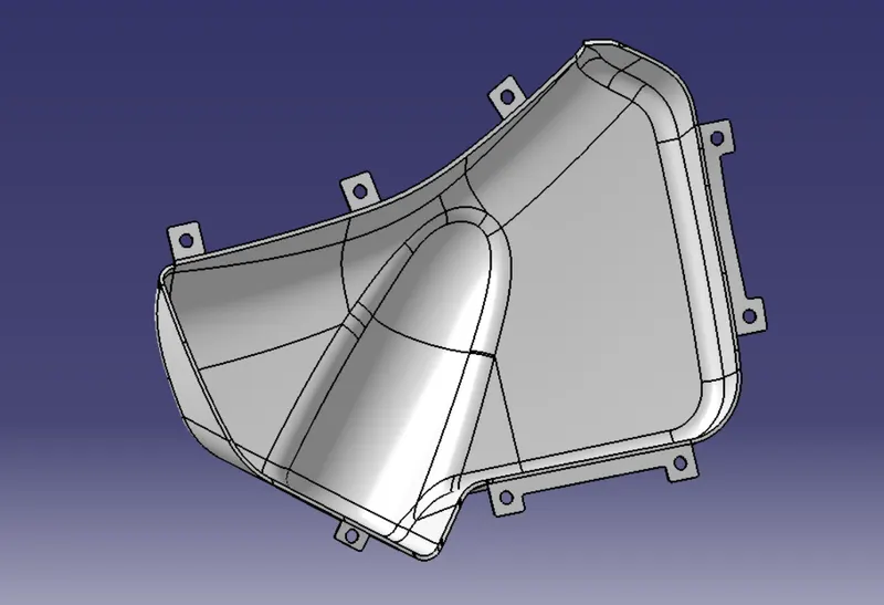
Map pockets can be created integrally within the door trim panel by forming a projection region outwardly towards the passenger compartment and then providing a separate panel attached to the rear outboard surface of the trim panel. This type of map pocket protrudes into the passenger compartment. Another type of map pocket such as a recessed map pocket can also be formed within the door assembly such that the storage compartment of the map pocket is generally located between the trim panel and the outer metal panel of the vehicle door. An aperture in the door trim panel defines the opening into the map pocket. Generally, these types of map pockets are formed by a separate map pocket assembly which is fastened to the rear surface of the trim panel. The map pocket assembly includes a front portion and a separate rear portion which are connected together to form the map pocket assembly and define the storage compartment. The rear portion defines a rear wall of the map pocket assembly. The front portion defines a lower front wall and a pair of side walls. The region above the lower front wall is generally open to provide access to the storage compartment of the map pocket. The map pocket assembly is then attached to the rear surface of the door trim panel such that the opening of the map pocket is generally aligned with an opening formed in the door trim panel.
Draft Analysis:
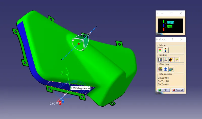
OUTER MAP POCKET
Draft Analysis
FINAL BODY: