Week 11 - Final project
DESIGN AND DEVELOPMENT OF A DOOR TRIM PANEL :
Aim:
To Design and Develop the Closed Surface and B side Engineering Features of Door Trim Panel from the given Class-A surface by Using CATIAV5.
Explanation:
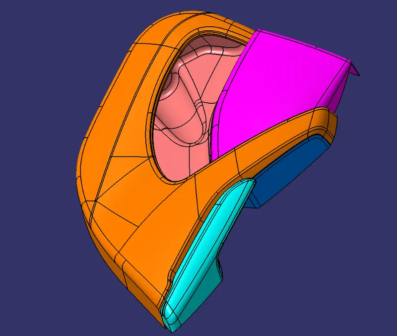
- Extract the Class A surface for Mapping Pocket, Bottle Holder, Door Arm Rest, and Lower Substrate from the given surface of a door trim panel.
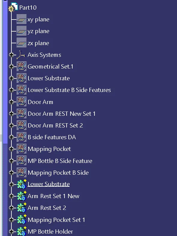
- Create a geometrical set for Mapping Pocket, Bottle Holder, Door Arm Rest, and Lower Substrate.
- Create a Tooling Axis and Sliding Axis for all the Parts to do Draft analysis.
- Create Class B Surface for all parts by simply offset the class A Surface by 2mm.
- Then Create Class C Surface by Sweeping from Class A surface Edge with the support of Tooling Axis by 3deg and 90 deg.
- Join Class A, B & C Surface to form Closed Surface.
- Create a Solid part from the Closed Surface of every part.
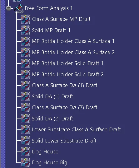
- Then do a Draft analysis for the solid parts of the Mapping Pocket, Bottle Holder, Door Arm Rest, and Lower Substrate with the Tooling Axis as Reference.
- Create B Side engineering features of the Mapping Pocket, Bottle Holder, Door Arm Rest, and Lower Substrate like Four-way locator, Two-way locator, Ribs, Snap-fit, Pushpin, Dog House, and Heat Stake.
- Engineering features are created by undergoing all the Dimensions and rules of Plastic Design.
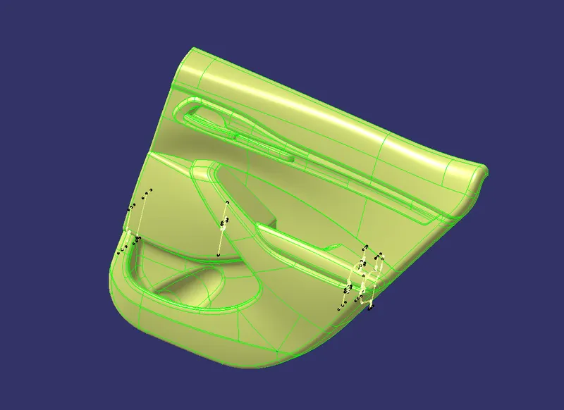
Class A Surface of Door Trim Panel :
Mapping Pocket :
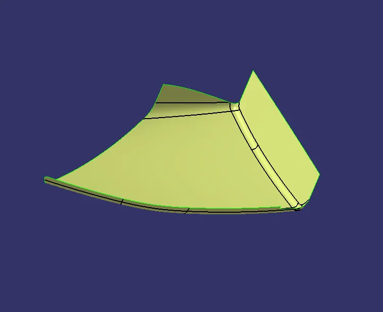
Class A Surface
Extraction of Class A surface of mapping pocket from the Door trim panel Surface.
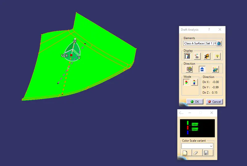
Draft Analysis for Class A Surface
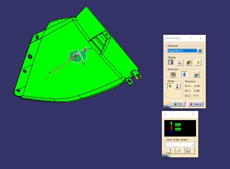
Did a draft analysis of class A surface of mapping pocket with the help of Tooling Axis which the draft should be above 3deg.
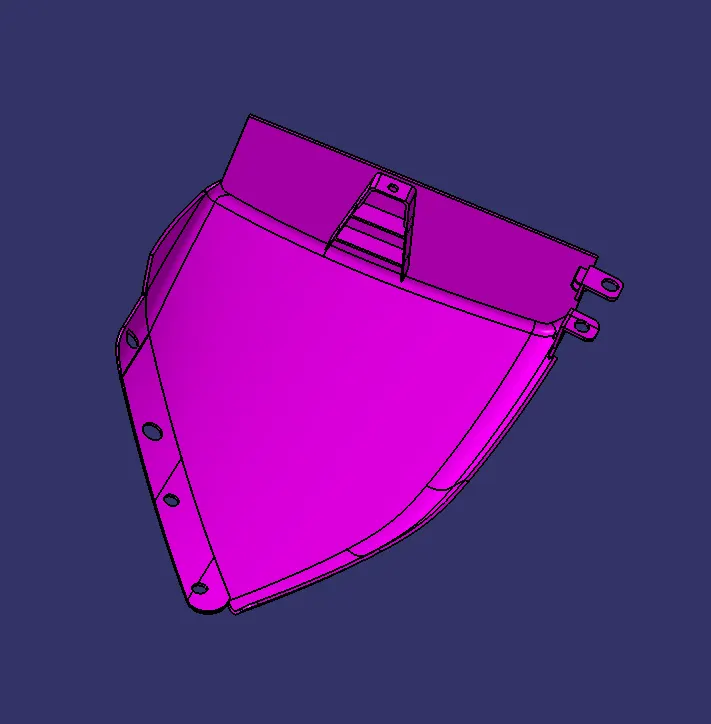
Solid Part
Created Class B Surface from the Class A surface by simply offsetting for 2mm and did Sweep from Class A surface with 3 & 90 deg Sweep angle with the tooling axis support. Finally attached all the engineering features on the class B surface.
Draft Analysis for Solid part
Did a draft analysis of solid mapping pocket with the help of Tooling Axis which the draft should be above 3deg.
Bottle Holder :
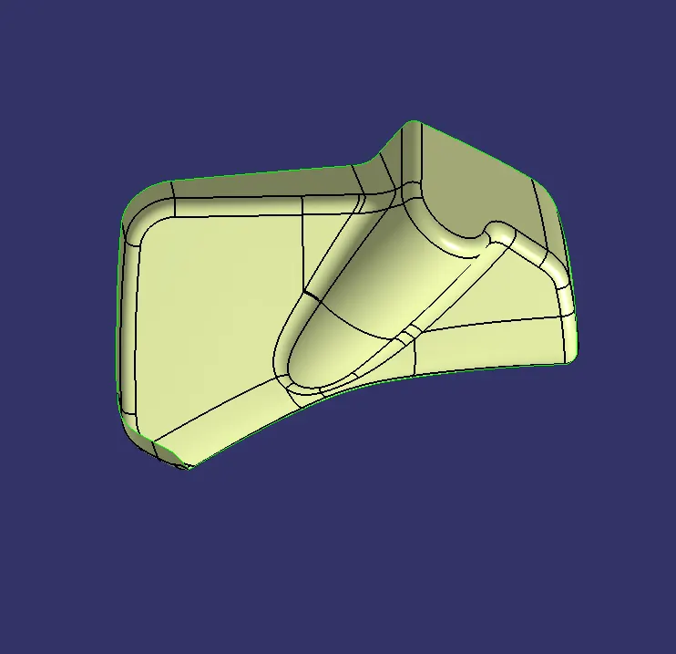
Class A Surface
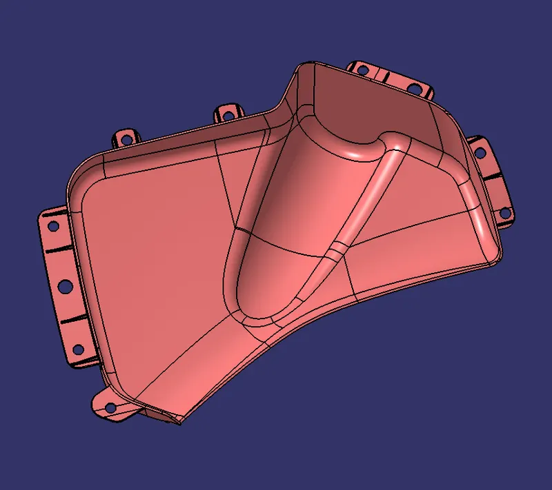
Extraction of Class A surface of Bottle Holder from the Door trim panel Surface.
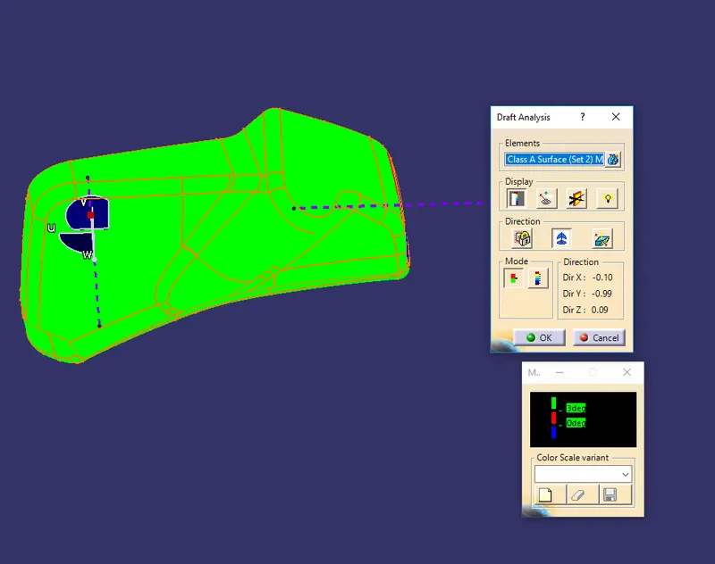
Draft Analysis for Class A Surface (1)
Did a draft analysis of class A surface of Bottle holder with the help of Tooling Axis (1) which the draft should be above 3deg.
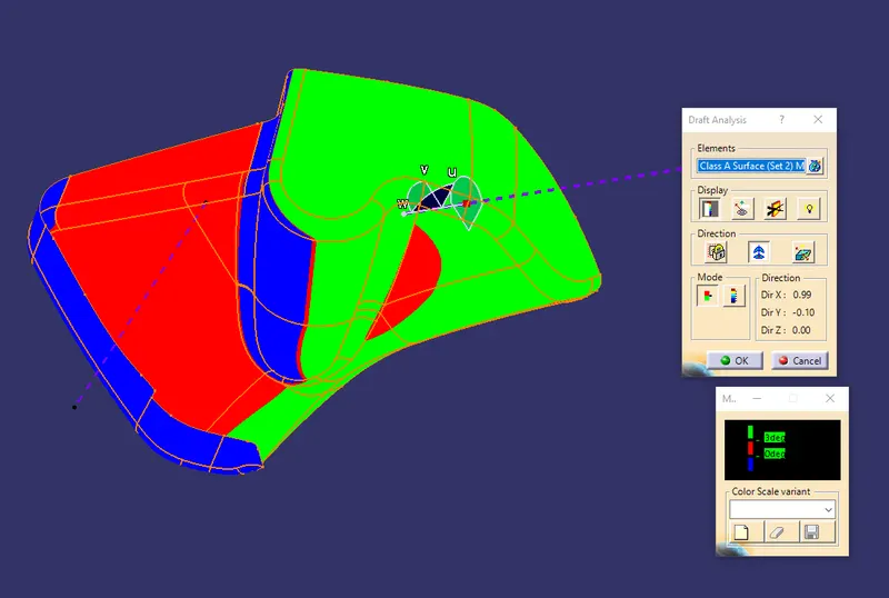
Draft Analysis for Class A Surface (2)
Did a draft analysis of class A surface of Bottle holder with the help of Side Core Axis (2), Because we can't clear the draft analysis by Tooling Axis. which the draft should be above 3deg.
Solid Part
Created Class B Surface from the Class A surface by simply offsetting for 2mm and did Sweep from Class A surface with 3 & 90 deg Sweep angle with the tooling axis support. Finally attached all the engineering features on the class B surface.
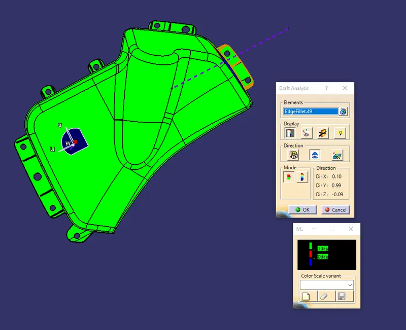
Draft Analysis for Solid part(1)
Did a draft analysis of solid Bottle Holder with the help of Tooling Axis(1) which the draft should be above 3deg.
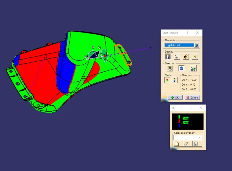
Draft Analysis for Solid part
Did a draft analysis of class A surface of Bottle holder with the help of Side Core Axis (2), Because we can't clear the draft analysis by Tooling Axis. which the draft should be above 3deg.
Door Arm Rest:
Class A Surface
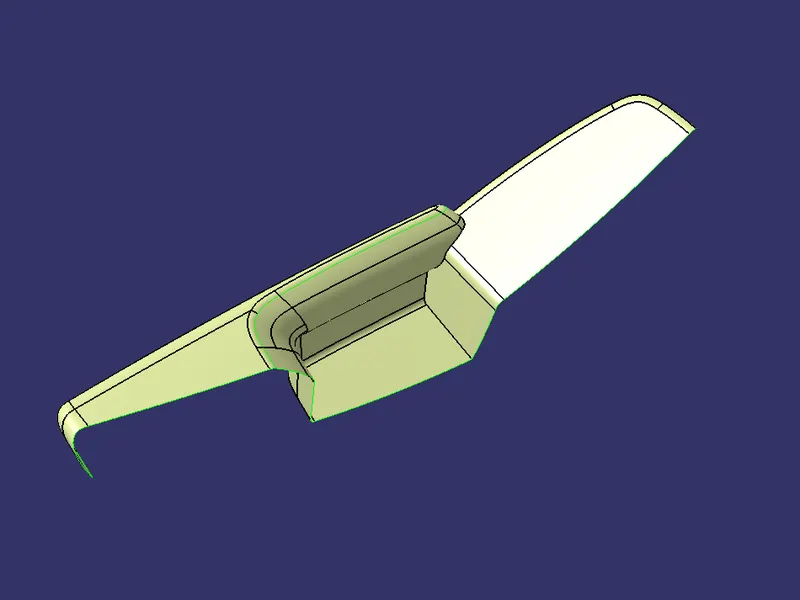
Extraction of Class A surface of Door Arm Rest from the Door trim panel Surface. Then we are splitting the Door Arm Rest into two-part Set 1 and Set 2. Because we can't clear draft analysis with a single tooling axis. That's why we split it into two and created two tooling axis and draft analysis separately.
Set 1:
Class A Surface
Extraction of Class A surface of Set 1 from the Door armrest Surface.
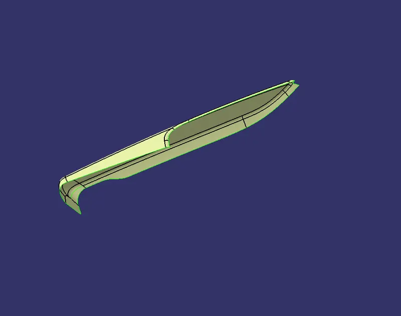
Draft Analysis for Class A Surface
Did a draft analysis of class A surface of Door armrest(set 1) with the help of Tooling Axis which the draft should be above 3deg.
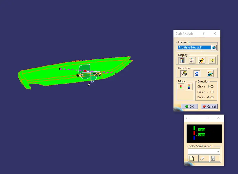
Solid Part
Created Class B Surface from the Class A surface by simply offsetting for 2mm and did Sweep from Class A surface with 3 & 90 deg Sweep angle with the tooling axis support. Finally attached all the engineering features on the class B surface.
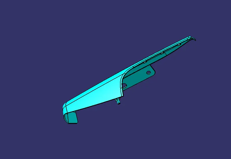
Draft Analysis for Solid part
Did a draft analysis of solid Door Arm Rest (set 1) with the help of Tooling Axis which the draft should be above 3deg.
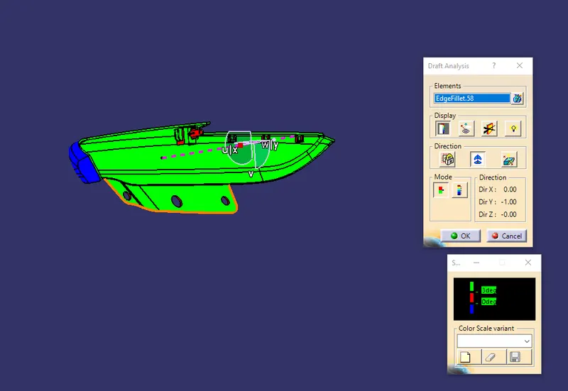
Set 2 :
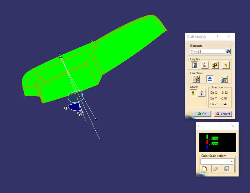
Draft Analysis for Class A Surface
Did a draft analysis of class A surface of Door armrest(set 2) with the help of Tooling Axis which the draft should be above 3deg.
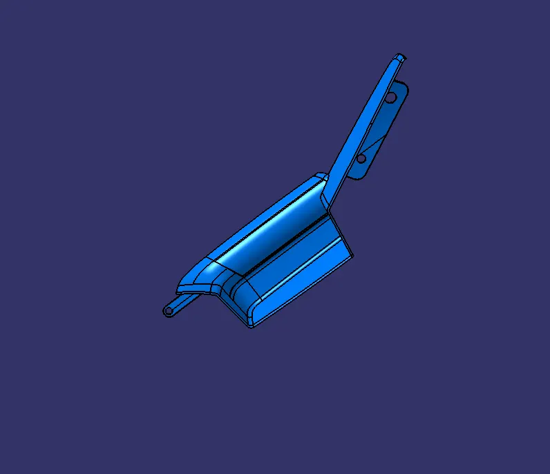
Solid Part
Created Class B Surface from the Class A surface by simply offsetting for 2mm and did Sweep from Class A surface with 3 & 90 deg Sweep angle with the tooling axis support. Finally attached all the engineering features on the class B surface.
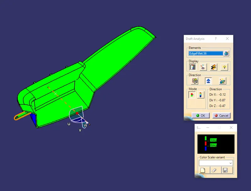
Draft Analysis for Solid part
Did a draft analysis of solid Door Arm Rest (set 1) with the help of Tooling Axis which the draft should be above 3deg.
Lower Substrate:
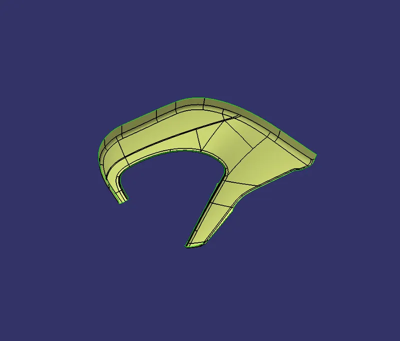
Class A Surface
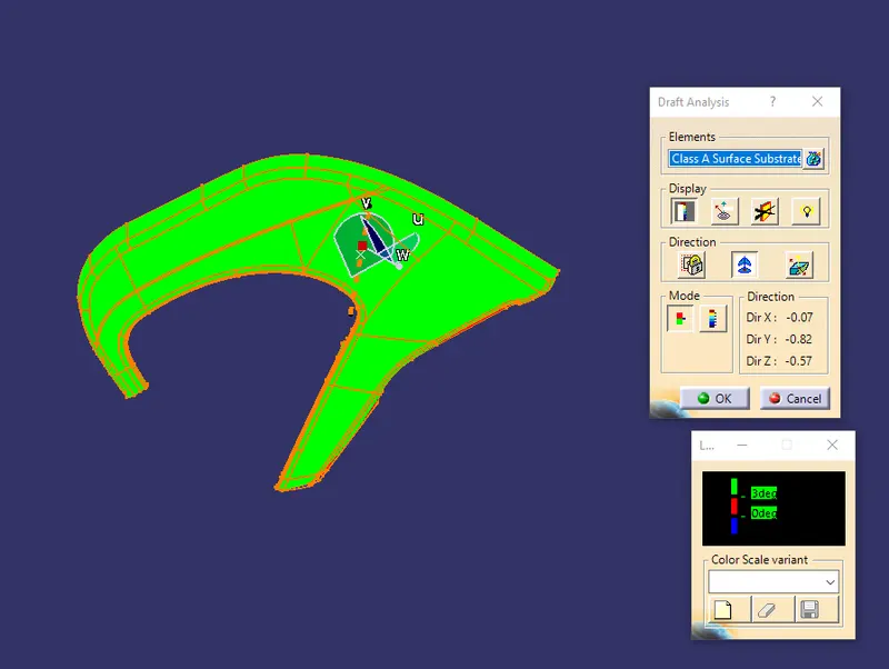
Extraction of Class A surface of Lower Substrate from the Door trim panel Surface.
Draft Analysis for Class A Surface
Did a draft analysis of class A surface of Lower Substrate with the help of Tooling Axis which the draft should be above 3deg.
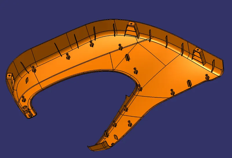
Solid Part
Created Class B Surface from the Class A surface by simply offsetting for 2mm and did Sweep from Class A surface with 3 & 90 deg Sweep angle with the tooling axis support. Finally attached all the engineering features on the class B surface.
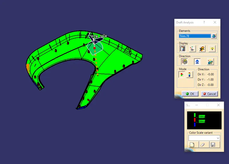
Draft Analysis for Solid part
Did a draft analysis of solid Lower Substrate with the help of Tooling Axis which the draft should be above 3deg.
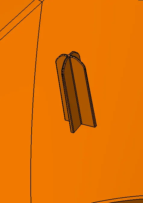
Four-Way Locator :
Four-way means you prevent movement at Two Axis (+X, -X, +Y, and -Y) on the plane. Generally, it is a cylindrical pin fixed on the B Surface. It has a 0.5 deg draft, 3X45 deg Chamfer, and fillet 0.5mm.
Two-Way Locator :
Two-way means you prevent movement at one Axis on the plane. Generally, it is a cylindrical pin fixed on the B Surface. It has a 0.5 deg draft, 3X45 deg Chamfer, and fillet 0.5mm.
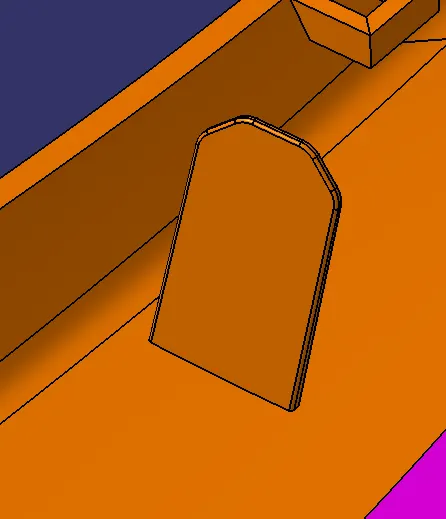
Snap Fit:
A snap-fit is an assembly method used to attach flexible parts, usually plastic, to form the final product by pushing the parts interlocking two components together.
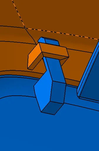
Heat Stake:
Staking is the process of connecting two components by creating an interference fit between the two pieces. A staking punch is then used to compress the boss radially and form an interference fit between the workpieces. This forms a permanent joint. It is a 0.5 deg draft and they are fixed with the ribs to give extra support to the heat stake.
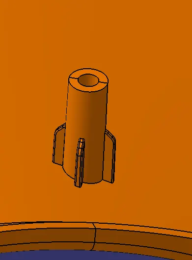
Heat Stake with Dog House:
The Dog houses are used as supporting features. Dog houses are subjected to draft analysis to prevent breakage of the component during ejection from the mold cavity. The dog house is built on B-surface it has a 0.5 deg draft and a bottom wall thickness of 40% of Actual wall thickness and fillets 3mm at the edges.
Heat Stake is supported with the ribs and they are fixed on the surface of the dog house.
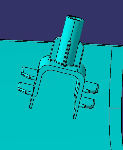
Pushpin With Dog house:
Pushpin slot is attached on the surface of the dog house as they are created on the B side that is used to fix the outer door sheet metal of the door trim panel.
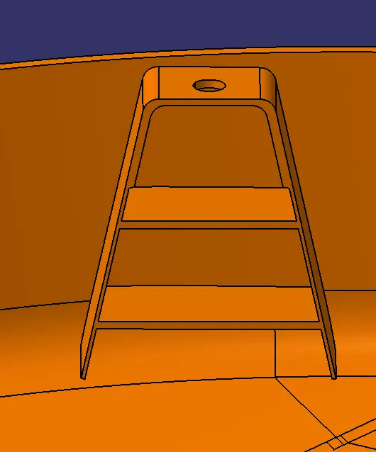
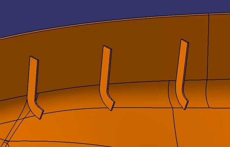
Ribs:
Ribs and gussets are features that generally are added to the primary wall of a plastic part for structural purposes. This could be to help the part resist deflection under load or to resist warpage. When adding ribs to the primary wall, the plastics designer must always consider manufacturability issues. It has a 0.5 deg draft.
B Surface Engineering Feature of Solid Part :
All the parts like Mapping Pocket, Bottle Holder, Lower Substrate, Door Arm Rest (set 1), and Door Arm Rest (set2) are joined by means of Snap fits and Heat stake with the help of Two & Four-way Locators. Ribs are used to strengthen the plastic body. Push Pin Slot with Dog House is used to fit the Door Trim Panel with the BIW Part. These engineering features are designed and developed on the B side Surface.
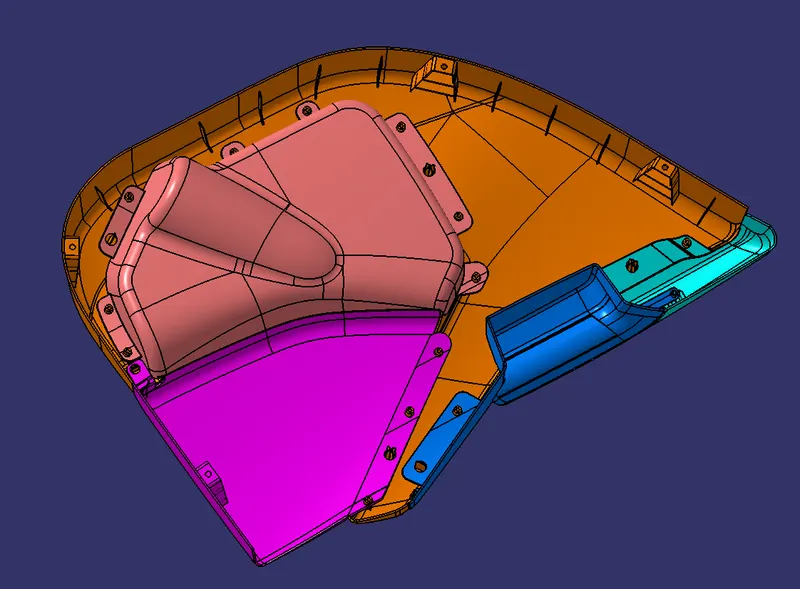
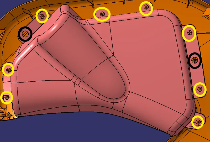
1)Mapping Pocket
- Black Circle shows the Four and Two-way Locators are mostly placed at the two extreme ends of the part because then only it can easy to locate and prevent the movement of the part.
- Yellow Circle shows the Heat Stake they will be placed at the extreme edge to arrest the movement of the part and also join the Mapping pocket and Lower Substrate.
- The green circle shows the Pushpin with the dog house which is used to attach the part to BIW.
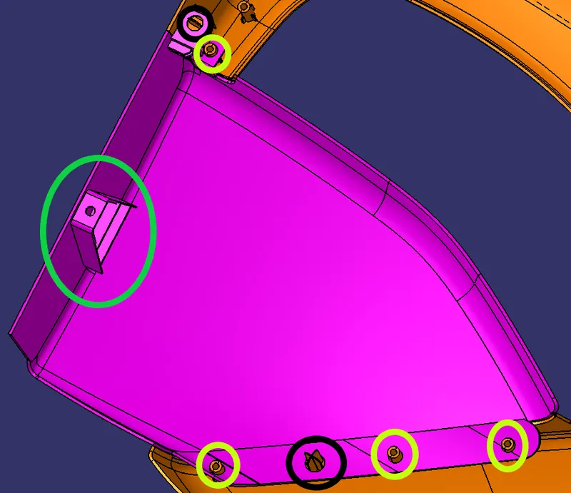
2)Bottle Holder
- Black Circle shows the Four and Two-way Locators are mostly placed at the two extreme ends of the part because then only it can easy to locate and prevent the movement of the part.
- Yellow Circle shows the Heat Stake which will join the Bottle Holder and Lower Substrate.
- Heat stakes are placed at the edges and the lower side of the bottle cup because the force will be heavy while placing the bottle in the cup.
3)Door Arm Rest
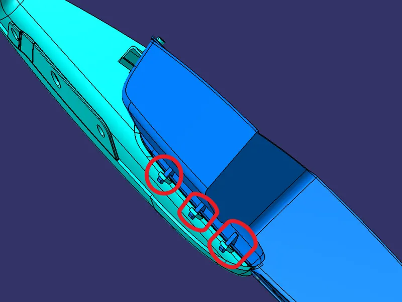
In the door armrest, we have divided the part into two as Set1 and Set 2. They are joined by means of a Snap-fit which is marked in a red circle because it's difficult to use heat stake at the lower joining area.
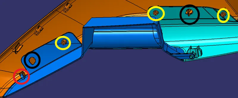
- Black Circle shows the Four and Two-way Locators are mostly placed at the two extreme ends of the part because then only it can easy to locate and prevent the movement of the part.
- Yellow Circle shows the Heat Stake which will join the Door Arm Rest and Lower Substrate.
- Red Circle shows the Snap-fit which will also use to lock the Door Arm Rest and Lower Substrate.
4)Lower Substrate
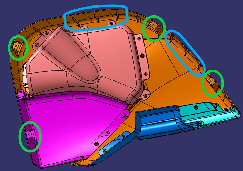
- Blue Circle shows the Ribs as they are used to strengthen the lower substrate to give additional support.
- The green circle shows the Pushpin with Dog house which is used to fit the door trim panel to the BIW.
- The lower substrate is the important part that is joined with all the parts like Mapping Pocket, Bottle Holder, and Door Arm Rest.
Class A Surface of Solid Part:
Feature Tree
Geometric and Solid
Draft Analysis
Result and Conclusion:
Thus, the Closed Surface is formed by Class A, B & C surfaces and the closed surface is solid. Then Engineering features are designed and developed on the B Side surface by using the CATIA V5 tool.